Table of Contents
Advertisement
Quick Links
SAFETY INFORMATION
WARNING
To ensure safe operation, and in order to exploit to the full the functionality of the meter, please follow
the directions in this section carefully.
This multimeter has been designed according to IEC-1010 concerning electronic measuring instruments
with an overvoltage category CAT ((( 600V and pollution 2.
Follow all safety and operating instructions to ensure that the meter is used safely and is kept in good
operating condition.
With proper use and care, the digital meter will give you years of satisfactory service.
1.1 PRELIMINARY
1.1.1 When using the meter, the user must observe all normal safety rules concerning:
( Protection against the dangers of electrical current.
( Protection of the meter against misuse.
1.1.2 When the meter is delivered, check that it has not been damaged in transit.
1.1.3 When poor condition under harsh preservation or shipping conditions caused, inspect and confirm
this meter without delay.
1.1.4 Test leads must be in good condition. Before using verify that the insulation on test leads is not
damaged and/or the leads wire is not exposed.
1.1.5 Full compliance with safety standards can be guaranteed only if used with test leads supplied. If
necessary, they must be replaced with the same model or
same electric ratings.
1.2 DURING USE
1.2.1 Before using, you must select the right input jack, function and range.
1.2.2 Never exceed the protection limit values indicated in specifications for each range of measurement.
1.2.3 When the meter is linked to a measurement circuit, do not touch unused terminals.
1.2.4 At the manual range, when the value scale to be measured is unknown beforehand, set the range
selector at the highest position.
1.2.5 Do not measure voltage if the voltage on the terminals exceeds 600V above earth ground.
1.2.6 Always be careful when working with voltages above 60V DC or 30V AC rms, keep fingers behind
the probe barriers while measuring.
1.2.7 Never connect the meter leads across a voltage source while the transform switch is in the current,
resistance, temperature, diode or continuity mode. Doing so can damage the meter.
MS6231
DIGITAL
ENGINE ANALYZER
OPERATOR'S MANUAL
Advertisement
Table of Contents

Related Manuals for Mastech ms6231


Summary of Contents for Mastech ms6231
- Page 1 MS6231 DIGITAL ENGINE ANALYZER OPERATOR’S MANUAL SAFETY INFORMATION WARNING To ensure safe operation, and in order to exploit to the full the functionality of the meter, please follow the directions in this section carefully. This multimeter has been designed according to IEC-1010 concerning electronic measuring instruments with an overvoltage category CAT ((( 600V and pollution 2.
-
Page 2: Maintenance
1.2.8 Before rotating the transform switch to change functions and ranges, disconnect test leads from the circuit under test. 1.2.9 Never perform resistance, temperature, diode and continuity measurements on live circuits. 1.2.10 Never use the meter under the condition of the explosive air, steam or dirt. 1.2.11 If any faults or abnormalities are observed, the meter can not be used any more and it has to be checked out. -
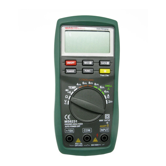
Page 3: Names Of Components
- This meter is a portable professional measuring instrument with handsome LCD and back light easily reading. - Single operation of a transform switch makes measurement convenient. Overload protection and low battery indication are provided, this meter is ideal for use in the fields, workshop, school, hobby and home applications. - Page 4 (12) (11) (10) ( RANGE Button This button is used to transform Auto range or manual range. ( FUNC. Button This button is used to transform function. ( DATA-H Button This Button is used to the switch of data hold. ( MAX.H Button This Button is used to the switch of maximum value hold.
-
Page 5: General Specifications
3. SPECIFICATIONS Accuracy is specified for a period of year after calibration and at 18℃ to 28℃( 64(F to 82(F) with relative humidity to 75%. 3.1 GENERAL SPECIFICATIONS 3.1.1 Auto ranges and manual range. 3.1.2 Overrange protection for all ranges. 3.1.3 Max. - Page 6 3.2.2 AC Voltage Range Resolution Accuracy 200m 0.1mV 0.001V ((0.8% of rdg + 3 digits) 0.01V 200V 0.1V 600V ((1.0% of rdg + 3 digits) - Input Impedance: 10M( - Overload Protection: 200mV range: 250V DC or AC rms, 2V-600V ranges: 600V DC or AC rms. - Frequency Range: 40 to 400Hz - Response: Average, calibrated in rms of sine wave.
- Page 7 mete 1mV/1 ((1.2 % of rdg + 3 2000A digits) Typical ((2.0 %) (DC) /1mV 2000A - Overload Protection: 250V DC or 250V rms AC. - Max. Input Voltage: 200mV 3.2.6 AC Current (with clamp, optional) Range Resolut Accuracy mete 0.1mV ((1.5 % of rdg + 5 200A...
- Page 8 3.2.9 Temperature Range -20℃ to 1000℃ Resoluti 1℃ ( ( 5% of rdg + -20℃ to 0℃ 4digits) ( ( 1% of rdg + 0℃ to 400℃ Accurac 3digits) ( ( 2% of rdg + 400℃ 1000℃ 3digits) Range -0℉ to 1800℉ Resoluti 1℉...
-
Page 9: Preparation For Measurement
4.2 DATA HOLD If you need data hold when measuring, you can put on “DATA-H” button, it will hold the reading; if you put the button again, data hold is not continue. 4.3 MAXIMUM VALUE HOLD If you need data hold when measuring, you can put on “MAX.H” button, it will hold the maximum value; if you put the button again, maximum value hold is not continue. -
Page 10: Measuring Dc Voltage
accordingly. When the value scale to be measured is unknown beforehand, set the range selector at the highest position. 4.3.4 When connection, first connect to the public testing line, then to the electriferous testing line. When you’ll remove it, you should remove the elecriferous one. 4.10 MEASURING DC VOLTAGE WARNING You can’t input the voltage which more than... -
Page 11: Measuring Ac Voltage
the higher range has to be selected. ( At the manual range mode, when the value scale to be measured is unknown beforehand, set the range selector at the highest position. Application 1: Use 2V range to test the end state of the divider. Take the high voltage line away from the cover of the divider, then connect with the iron. -
Page 12: Measuring Dc Current
NOTE: ( At the little voltage range, the meter will show unsteady reading when test leads haven’t reach the circuit, it’s normal because the meter is very sensitivity. When test leads touch the circuit, you can get the true reading. ( At the manual range mode, when only the figure ‘OL’... -
Page 13: Dc Current Measuring
4.12.1 Connect the black test lead to the COM jack and the red test lead to the 10A jack. 4.12.2 Set the transform switch at the A range position. 4.12.3 Put down the "FUNC." to enter the DC measurement. Auto range or manual range can be transformed by putting the “RANGE”. -
Page 14: Measuring Ac Current
( At the manual range mode, when the value scale to be measured is unknown beforehand, set the range selector at the highest position. ( Select the DC clamp to measure the DC current. ( Matching problem about the meter and the sensitivity of the clamp: a. - Page 15 higher range has to be selected. ( When the value scale to be measured is unknown beforehand, set the range selector at the highest position.( “ ” means the socket of 10A jack maximum current is 10A, no fuse protection. 4.15 AC CURRENT MEASURING (WITH CLAMP, OPTIONAL) 4.15.1 Connect the black output lead of clamp to the COM jack and the red one to the INPUT jack of the meter.
-
Page 16: Measuring Resistance
the higher range has to be selected. ( At the manual range mode, when the value scale to be measured is unknown beforehand, set the range selector at the highest position. ( Select the AC clamp to measure the AC current. ( Matching problem about the meter and the sensitivity of the clamp: a. -
Page 17: Measuring Temperature
4.17 MEASURING TEMPERATURE(℃) WARNING To avoid electrical shock, do not connect the thermocouples with the electriferous circuit. 4.17.1 Set the transform switch at the TEMP range position. 4.17.2 Put down the "FUNC." to enter the ℃ measurement. 4.17.3 The LCD display will show the current environment temperature. 4.17.4 When measuring the temperature with thermocouple, ‘K’... - Page 18 this meter can be used. Insert the black plug to the COM jack and the red one to the INPUT jack, touch the end of the temperature sensor to the area or surface of the object for measurement. 4.18.5 You can get reading from LCD. NOTE: ( With better hermetization, the meter’s temperature measured circuit and environment need a little longer time to reach heat balance, and then accurate reading can be gotten.
-
Page 19: Testing Diode
4.19.3 Connect the black test lead to the iron or the negative pole of the storage cell, and the red one to the low voltage connection pole of the divider or the negative pole of the ignition winding for measurement. 4.19.4 You can get reading from LCD after the engine is started. -
Page 20: Continuity Test
figure‘OL’will be displayed. ( When the input is not connected, i.e. at open circuit, the figure ‘OL’ will be displayed. 4.22 CONTINUITY TEST WARNING When testing the circuit continuity, be sure that the power of the circuit has been shut down and all capacitors have been discharged fully. -
Page 21: Battery Replacement
of the circuit under testing. 4.22.5 If continuity exists (i.e., resistance less than about 50(), built-in buzzer will sound. NOTE: ( If the input open circuit (or the circuit resistance measured is higher than 200(), then the figure ’0L’ will be displayed.
Need help?
Do you have a question about the ms6231 and is the answer not in the manual?
Questions and answers