Page 1
Table of Contents 1.SAFETY INFORMATION ..........1 Introduction 2.INSTRUMENT PANEL DESCRIPTION ....... 3 3. PANEL FEATURE DESCRIPTIONS ....... 4 
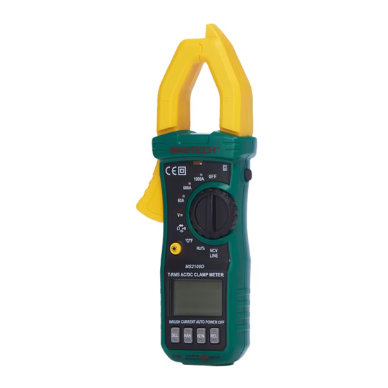
This series of digital clamp meters has been designed and 4. FUNCTION BUTTON DESCRIPTIONS ......6 manufactured in accordance with international electrotechnical safety 5.
Page 2
Safety Information MS2109 Series Digital Clamp Meter Operating Precautions Overview of Functions for MS2109 Series Products * The instrument must be warmed up for 30 seconds before taking measurements. Model MS2109B MS2109C MS2109D Features * Do not use the instrument or the test leads if they are visibly...
Page 3
* Do not exceed the input limit specified for each range to avoid Instrument Panel Description damaging the instrument. * When measuring current, the test leads should not be inserted into the input jacks. * When holding the clamp meter during measurement, your fingers should remain behind the safety guard on the body of the meter.
Page 4
Panel Feature Description automatically updated. Feature Description 5. Hz/%: It switches between frequency and duty cycle and is active in AC NCV Sensing This is the non-contact voltage (NCV) detection area. When in the NCV mode. Area mode, if voltage is detected in this area, the NCV alarm will activate. 6.
Page 5
Symbol Explanation Symbol Explanation process starting from when the button was pressed. Data Hold Low Voltage Indicator APO SET (Auto Power Off Setting Button) Diode Continuity Test Measurement Indicator ■ Description: If this button is pressed before turning on the power, Maximum Value Low-Pass the instrument will automatically power off after about 15 minutes.
Page 6
Technical Specifications REL△ (Relative Value Measurement Button) General Specifications ■ Description: Press this button to enter relative value measurement ■ Operating Conditions: mode. The currently displayed value will be set as the reference value Working Temperature (Humidity): 0°C to 40°C(<80%RH) for relative measurements, and subsequent displayed values will be Storage Temperature (Humidity): -10°C to 60°C(<70%RH, with the actual measurement minus this reference value.
Page 7
■ Maximum clamp Opening Size: φ23mm 0.001A ■ Maximum Measurable Conductor Size: φ23mm。 0.01A ■ Dimensions: 194(L) × 72(W) × 35(H) mm ±(2.5%+10d) 200A 0.1A ■ Weight: Approximately 230 g (including batteries) ■ Accessories: 1. User manual ×1 600A 2. Test leads ×1 set Frequency Response: MS2109B: 40–60Hz 3.
Page 8
200mV/400mV/600mV 0.1mV ±(0.5%+3d) Range Resolution Accuracy 2V/4V/6V 0.001V 200/400/600 0.1 ±(1.0%+10d) 20V/40V/60V 0.01V ±(0.8%+5d) 2k/4k/6k 0.001K 200V/400V/600V 0.1V 20k/40k/60k 0.01K 600V/1000V ±(1.0%+5d) ±(0.8%+5d) 200k/400k/600k 0.1K Input impedance: 10MΩ 2M/4M/6M 0.001M Maximum input voltage: 600V DC or 600V AC RMS 0.01 M 20M/40M/60M...
Page 9
-20℃ to 0℃ ±(5% reading + 4 digits) 10MHz 0.01MHz Accurac 0℃ to 400℃ ±(2% reading + 3 digits) Overload protection: 250V DC or AC RMS Capacitance (CAP) (not applicable to MS2109B) 400℃ to 1000℃ ±(3% reading + 3 digits) Range Accuracy Resolution...
Page 10
■ Connect the black test lead to the COM input jack. Connect the red high-voltage (>600V) conductors. test lead to the INPUT jack. ■ Turn the dial to the desired Current range. ■ Use the test leads to measure the voltage of the circuit being tested ■...
Page 11
tested. diode and the black test lead to the cathode (negative terminal). ■ Read the resistance value from the LCD. ■ Read the forward voltage drop value of the diode on the LCD. Note: Note: 1. If the test leads are shorted while in the Ω range, due to the 1.
Page 12
■ Turn the dial to the ℃/℉ range. beep” alarm sound, alerting the user to the presence of voltage. ■ Press the SEL button to switch between ℃ and ℉ modes. Please proceed with caution ■ The LCD will display the ambient temperature of the instrument. Note: ■...
Page 13
2. Detection results may be affected by factors such as socket components connected in parallel with the circuit being tested may design, insulation thickness, and material type. affect the accuracy of the measurement. 3. External sources of interference (e.g., flashlights, motors, etc.) may affect the the instrument, causing inaccurate detection.
Page 14
amount of detergent. Do not use chemical solvents to clean the case. the fuse: 1. Unscrew the screws securing the back cover and remove the ■ Repairs and calibrations must be performed by professionals. back cover. ■ To prevent contamination or damage from static electricity, take 2.
Need help?
Do you have a question about the MS2109 Series and is the answer not in the manual?
Questions and answers