
Related Manuals for Mastech MS5308


Summary of Contents for Mastech MS5308
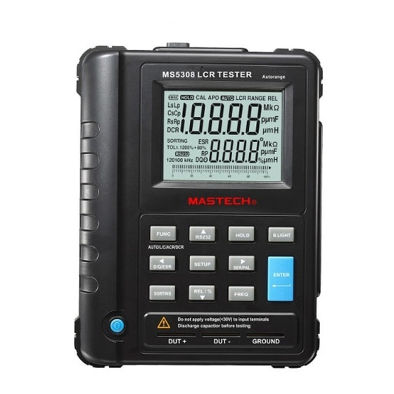
- Page 1 Auto Range LCR Meter RANGE Ls Lp Cs Cp p mF Rs Rp SORTING 1205% + 80% ±. p mF 120100 kHz...
-
Page 2: Table Of Contents
CONTENTS CONTENTS 1. General instructions 7. Additional Functions ........1 ........12 1.1 Panel Description ...........1 7.1 Auto Power Off Function ........12 1.2 Inspection ..............3 7.2 Backlight Function ..........12 1.3 Accessories ............3 7.3 Battery Power Detection Function .......13 2. Safety Instructions ........3 8. -
Page 3: General Instructions
1. General Instructions Thank you for purchasing this LCR digital bridge meter. It is a professional instrument for measuring inductance, capacitance and resistance. It has many features, such as automatic identification, automatic measurement range, high measurement accuracy and speed, wide measuring range and so on. -
Page 4: Inspection
1.2 Inspection C s: Capacitance series connection measurement mode R P: Resistance parallel connection measurement mode When you get a new LCR meter, please check the instrument Rs: Resistance series connection measurement mode and its accessories. If something is damaged or missed, DCR: Resistance DC measurement mode please contact the store you bought the instrument from for D: Wastage factor... -
Page 5: Functional Characteristics Description
4. Functional Characteristics Description Table 1 Resistance measurement scope 1. 19,999 (main)/1,999 (secondary) dual LCD display Measuring Range Resolution Accuracy Measurement Frequency 2. LCR measures with automatic identification and automatic 100Hz/120 200.00Ω 0.01Ω 1.0%+5d measurement range 100Hz/120 2.0000kΩ 0.1Ω 0.3%+5d 3. - Page 6 Table 2 Capacitance measurement scope Table 3 Inductance measurement scope Measuring Measuring Range Resolution Accuracy Range Resolution Accuracy Measurement Measurement Frequency Frequency 100Hz/120 20.000nF 100Hz/120 20.000mH 1.0%+5d 1.0%+5d 100Hz/120 200.00nF 0.01nF 0.5%+5d 100Hz/120 200.00mH 0.01mH 0.5%+5d 100Hz/120 2000.0nF 0.1nF 100Hz/120 2000.0mH 0.1mH 0.5%+5d...
-
Page 7: Meter Probe Measurement
5. Meter Probe Measurement Use Kelvin clip or SMD clamp to connect according to the following diagram: Schematic diagram for using Kelvin clip to measure Schematic diagram for using SMD clamp to measure Remarks: insert the plug correctly according to the diagram. Measurement can’t be done if inserted incorrectly Remarks: insert the plug correctly according to the diagram. -
Page 8: Measurement Operation Description
6. Measurement Operation Description modification item by operating Ok button, and confirm the settings. Press Comparison button again to quit selection 6.1 Automatic Measurement mode. When the instrument is turned on, the instrument will enter 6.4 Deviation Proportion Measurement automatic identification mode by default. At this time, insert the When the instrument is turned on, the instrument will switch object to be measured to the measurement side. -
Page 9: Battery Power Detection Function
7.3 Battery Power Detection Function: The meter has a Click NEXT to enter the next screen battery power detection function. Battery power includes four levels and displays on the LCD screen. When “ ” displays for battery, please replace battery. This meter uses 8 × 1.5V Size AA battery. - Page 10 Click OK to enter the next screen based on the diagram Click INSTALL and start installing Click NEXT...
-
Page 11: Data Transmission
Click finish, and the following icon will show on the desk Installation complete 9. Data Transmission Screen I Press Communication button. The RS232 symbol will show on the LCD display. At this time, you can send data via infrared port. Connect the infrared communication line between computer and LCR Meter. - Page 12 R-00-05-0555...
Need help?
Do you have a question about the MS5308 and is the answer not in the manual?
Questions and answers