Advertisement
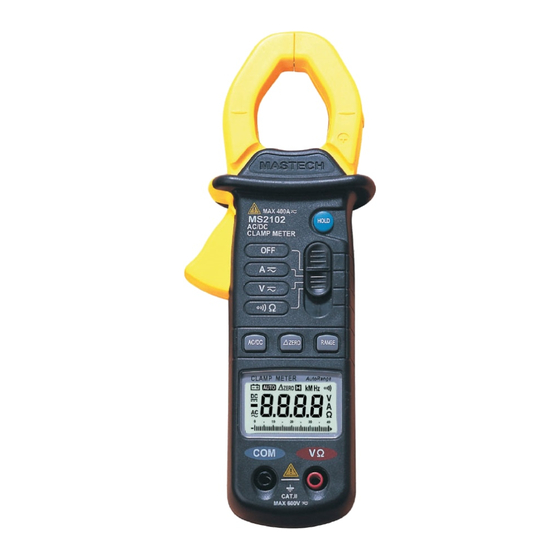
MINI CLAMP METER
MASTECH
MAX 400A
MS2102
HOLD
AC/DC
CLAMP METER
OFF
A
V
AC/DC
ZERO
RANGE
CLAMP METER
Auto Range
MkHz
AUTO
ZERO
DC
V
A
AC
0
10
20
30
40
COM
V
CAT II
MAX 600V
MS2102
1. GENERAL INSTRUCTIONS
1.1 Precaution safety measures
1.1.1 Preliminary
1.1.2 During use
1.1.3 Symbols
1.1.4 Instructions
1.2 Maintenance and Cleaning
1.3 Battery replacement
2. DESCRIPTION
2.1 Instrument Familiarization
2.2 LCD Display
2.3 Key pad
2.4 Transformer jaws
2.5 Terminals
3. TECHNICAL SPECIFICATIONS
3.1 General specifications
3.2 Measurement specifications
3.2.1 DC Current (autorange)
3.2.2 AC Current(autorange)
3.2.3 DC Voltage (autorange)
3.2.4 AC Voltage (autorange)
3.2.5 Resistance
3.2.6 Audible continuity
4. OPERATING INSTRUCTION
4.1 AC Current measurement
4.2 DC Current measurement
4.3 DC Voltage measurement
4.4 AC Voltage measurement
4.5 Resistance measurement
4.6 Continuity measurement
1
1
1
2
3
3
4
4
5
5
6
7
7
8
8
8
9
10
10
10
11
11
11
11
12
13
14
15
16
17
Advertisement
Table of Contents

Related Manuals for Mastech MS2102


Summary of Contents for Mastech MS2102
- Page 1 MS2102 1. GENERAL INSTRUCTIONS MINI CLAMP METER 1.1 Precaution safety measures 1.1.1 Preliminary 1.1.2 During use 1.1.3 Symbols 1.1.4 Instructions 1.2 Maintenance and Cleaning 1.3 Battery replacement 2. DESCRIPTION 2.1 Instrument Familiarization 2.2 LCD Display 2.3 Key pad MASTECH 2.4 Transformer jaws 2.5 Terminals...
-
Page 2: General Instructions
with the instrument. Before use, check that they are in 1.GENERAL INSTRUCTIONS good condition. This instrument has been designed according to IEC1010 concerning safety requirements for electronic measuring 1.1.2 During use instruments and hand-held current clamps. • Before measurement, warm up for at least 30 seconds. To get the best service from this instrument, read carefully •... -
Page 3: Symbols
1.1.3 Symbols: • If any faults or abnormalities are observed, take the Symbols used in this manual and on the instrument: instrument out of service and ensure that it cannot be used until it has been checked out. Note-Important safety information, refer to the instruction manual. -
Page 4: Description
11. HOLD key 2. DESCRIPTION 2.1 Instrument Familiarization 2.2 LCD Display MkHz AUTO ZERO MASTECH Low battery indication MAX 400A MS2102 HOLD Auto range indication AC/DC AUTO CLAMP METER Zero reading indication ZERO Hold data indication Continuity function indication Voltage measurement indication... -
Page 5: Technical Specifications
2.3 Keypad 2.5 Terminals HOLD key: V Ω : terminal receiving the red lead for voltage, Fixes the display on the current value and memories it resistance, and continuity measurements. (short press). COM: terminal receiving the black lead for voltage, A second short press returns the clamp meter to normal resistance, and continuity measurements as a common mode. - Page 6 • Low battery indication: • Accuracy: The " " is displayed when the battery is under the ±(% of reading + number of digits) at 18°C to 28°C (64°F proper operation range. to 82°F) with relative humidity to 80%. • Auto power off time: 3.2.1 DC Current (autorange) If there is no key or dial operation for 30 minutes, the meter will power itself off to save battery consumption.
-
Page 7: Terminals
3.2.4 AC Voltage (autorange) 4.1 AC Current measurement Range Resolution Accuracy Make certain that all test leads are disconnected 400V 0.1V from the meter terminals. ±(1.0%+5) 600V • Set function switch to the A range. • Press "AC/DC" key to select " AC" function. Input impedance: 10MΩ... - Page 8 4.2 DC Current measurement 4.3 DC Voltage measurement Make certain that all test leads are disconnected Maximum input voltage of DCV range is 600Vdc. from the meter terminals. Do not attempt to take any voltage measurement Open and close the clamp jaw several times to that exceeds 600Vdc to avoid electrical shock demagnetize the clamp jaw before taking any DC and/or damage to the instrument.
-
Page 9: Resistance
4.4 AC Voltage measurement 4.5 Resistance measurement Maximum input voltage of ACV range is 600Vrms. Before taking any in-circuit resistance Do not attempt to take any voltage measurement measurement, remove power from the circuit that exceeds 600Vrms to avoid electrical shock being tested and discharge all capacitors. -
Page 10: Continuity Measurement
4.6 Continuity measurement CAUTION Before taking any in-circuit measurement, remove Using this appliance in an environment with a strong power from the circuit being tested and discharge radiated radio-frequency electro-magnetic field all capacitor in the circuit. (approximately 3V/m), may influence its measuring accuracy.
Need help?
Do you have a question about the MS2102 and is the answer not in the manual?
Questions and answers