Table of Contents
Advertisement
Quick Links
Advertisement
Table of Contents

Related Manuals for Mastech MS5901


Summary of Contents for Mastech MS5901
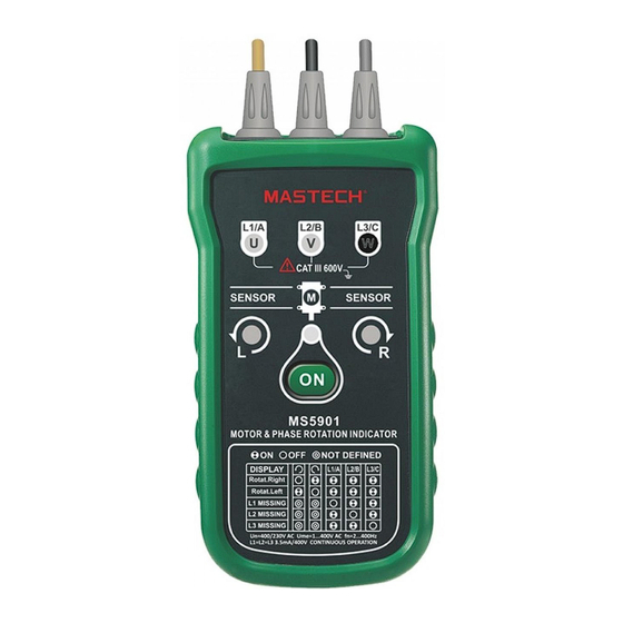
- Page 1 MS5901 Three Phase Rotation Indicator Users Manual...
-
Page 2: Table Of Contents
CONTENTS CONTENTS Replacing And Disposing Introdution............1 Of The Batteries........12 Accessories..........1 Specifications........14 Safety Information........2 List of Tables Symbols............4 1. Symbols..........4 Elements Of The Apparatus......5 2. Reliable Motor Using the Motor & Test Requirements........10 Phase Rotation Indicator......6 List of Figures Determine Rotary Field Direction....6 1. -
Page 3: Introdution
Introduction Safety Information Motor and Phase Rotation Indicator is a handheld, battery-operated instrument designed to detect CAUTION identifies conditions and actions that may the rotary field of three-phase systems and damage the apparatus. determine motor-rotation direction. Protection provided by the instrument will be impaired if used in a manner not specified by the WARNING manufacturer. -
Page 4: Symbols
• Be careful when working above 30 V ac rms, 42 V Symbols ac peak and 60 V dc. Such voltages pose a shock The following symbols appear on the Motor and hazard. Phase Rotation Indicator or in this manual. •... -
Page 6: Non-Contact Rotary Field Indication
The rotary indicator lights 3. Press the ON/OFF button. The green ON indicator shows that the instrument is ready for testing. WARNING Either the Clockwise or Counter Clockwise Rotary if the neutral conductor, N, is connected instead indicator illuminates showing the type of rotary of L1, L2, or L3. -
Page 7: Determine The Motor Connection
Table 2. Reliable Motor Test Requirements Note The bottom of the apparatus should be oriented towards the drive shaft . See the Orientation Symbol on the apparatus. Either the Clockwise or Counter Clockwise Rotary indicator illuminates showing the type of rotary field direction present. -
Page 8: Magnetic Field Detection
Magnetic Field Detection Cleaning Periodically wipe the case with a damp cloth and To detect a magnetic field, place the apparatus to mild detergent. Clean only with soap and water and a solenoid valve. A magnetic field is present if either the Clockwise or the Counter Clockwise remove any residue afterwards. -
Page 9: Specifications
The apparatus uses a 9 V battery (supplied). To replace the battery, follow these steps and refer Environmental to Figure 4: 0 °C to +40 °C Operating Temperature 1. Disconnect test leads from any power source. 2. Place the apparatus face down on a nonabrasive Operating Altitude 2000 m surface and loosen the battery-door screw with... -
Page 10: Determine Rotary Field Direction
Determine the Motor Connection Nominal Test Voltage 1 to 400 V AC (Ume) Nominal Test Currents less than 3.5 mA (In per phase) DONGGUAN HUAYI MASTECH COMPANY LIMITED Yuliangwei Industrial Area,Qingxi Frequency Range (fn) 2 to 400 Hz Dongguan,Guangdong,China http://www.p-mastech.com 00-05-4099...
Need help?
Do you have a question about the MS5901 and is the answer not in the manual?
Questions and answers