Table of Contents
Advertisement
Advertisement
Table of Contents

Related Manuals for Mastech MS5201


Summary of Contents for Mastech MS5201
- Page 1 DIGITAL INSULATION TESTER OPERATOR’S MANUAL...
-
Page 2: Table Of Contents
CONTENTS SAFETY INFORMATION ……………1 PRELIMINARY ……………2 DURING USE ……………3 SYMBOLS ……………4 MAINTENANCE ……………5 DESCRIPTION ……………6 NAMES OF COMPONENTS ……………9 SWITCH AND BUTTONS ELUCIDATE ……………10 SPECIFICATIONS ……………11 GENERAL SPECIFICATIONS ……………11 ELECTRICAL SPECIFICATIONS ……………12 OPERATING INSTRUCTION ……………16... - Page 3 SWITCH DISLOCATION ALARM ……………16 SOUND AND FLASH ALARM ……………16 READ HOLD ……………17 HAND OPERATING AND TIME MEASURING ……………17 PREPARATION FOR MEASUREMENT ……………18 MEASURING INSULATION RESISTANCE ……………19 MEASURING AC VOLTAGE ……………22 MEASURING DC VOLTAGE ……………24 MEASURING RESISTANCE ……………26 4.10 CONTINUITY TEST ……………27 MAINTENANCE ……………29...
-
Page 4: Safety Information
1. SAFETY INFORMATION This meter has been designed in general to comply with IEC 348 and according to IEC-1010 concerning about electronic measuring instruments with an overvoltage category 1000V CAT ΙΙ, 600V CAT Ш and pollution 2. Follow all safety and operating instructions to ensure that the meter is used safely and is kept in good operating condition. -
Page 5: Preliminary
1.1 PRELIMINARY 1.1.1 When using the meter, the user must observe all normal safety rules concerning: • Protection against the dangers of electrical current • Protection of the meter against misuse 1.1.2 When the meter is delivered, check that it has not been damaged in transit. -
Page 6: During Use
replaced with the same model or same electric ratings. 1.1.6 This meter must only be used by a competent trained person and in strict accordance with the operator’s manual. 1.2 DURING USE 1.2.1 Never exceed the protection limit values indicated in specifications for each range of measurement. -
Page 7: Symbols
1.2.6 Ensure all circuits are de-energized before measuring. 1.2.7 Before rotating the range switch to change ranges, disconnect test leads from the circuit under test. 1.2.8 If any faults or abnormalities are observed, the meter can not be used any more and it has to be checked out. 1.2.9 Never use the meter unless the rear case is in place and fastened fully. -
Page 8: Maintenance
DC (direct current) Continuity Buzzer 1.4 MAINTENANCE 1.4.1 Please do not attempt to adjust or repair the meter by removing the rear case while voltage is being applied. A technician who fully understands danger involved should only carry out such actions. 1.4.2 Before opening the battery cover of the meter, always disconnect test leads or test clips from all sources of electric current. -
Page 9: Description
2. DESCRIPTION - This meter has the function of sound and flash alarm. If the function switch and range switch is out of place, you will hear a humming sound per two seconds from the inside alarming system. This protection provides for meter to avoid damage by operation improperly. - Page 10 alarming system will give out a humming sound (per two seconds), and the red high voltage output indicator is flashing, which warns the operator to pay attention to the high output voltage, and avoid getting electric shock. - Overload protection and low battery indication is provided. - This meter is a portable professional measuring instrument with large LCD.
-
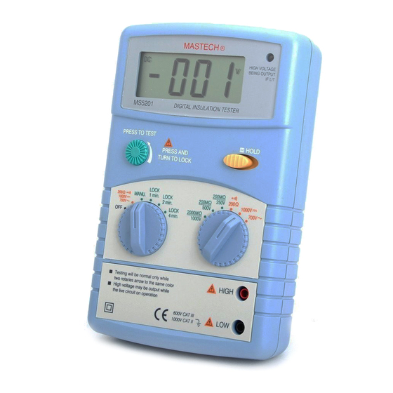
Page 12: Names Of Components
2.1 NAMES OF COMPONENTS (See Fig 3) High Voltage Output Indicator LCD Display Panel Test Button Data Hold Switch (D-H) Function Switch Range Switch HIGH Jack LOW Jack Battery Cover Case... -
Page 13: Switch And Buttons Elucidate
2.2 SWITCH AND BUTTONS ELUCIDATE • Function Switch This switch is used to select measure mode and the switch of power. • Range Switch This switch is used to select desired ranges. • Test Button This Button is used to the insulation resistance measurements. •... -
Page 14: Specifications
3 SPECIFICATIONS Accuracy is specified for a period of year after calibration and at 18 to 28 64°F to 82°F with relative humidity to 75%. 3.1 GENERAL SPECIFICATIONS 3.1.1 Max. Voltage Between Terminals And Earth Ground: 1000V DC or AC 3.1.2 Measuring method: Dual-slope integration A/D converter 3.1.3 Sampling Time: approx. -
Page 15: Electrical Specifications
3.1.10 Power Consumption: Approx. 5mA DC1000V AC750V 200Ω Approx. 30mA 200MΩ/250V Approx. 50mA 200MΩ/500V Approx. 100mA 2000MΩ/1000V 3.1.11 Low Battery Indication: ‘ ’ displayed 3.1.12 Operating Temperature: 0 to 40 32°F to 104°F 3.1.13 Operating Humidity: ≤85%RH 3.1.14 Storage Temperature: -10 to 50 10°F to 122°F 3.1.15 Dimension: 192×122×55 mm 3.1.16 Weight: Approx. - Page 16 3.2.1 Insulation Resistance Range 200MΩ/250V 200MΩ/500V 2000MΩ/1000V Test Voltage DC 250V±10% DC 500V±10% DC 1000V±10% Measuring Ranges 0 ~ 200MΩ 0 ~ 200MΩ 0 ~ 2000MΩ 0 ~ 1000MΩ 1000 MΩ~ 2000MΩ Accuracy ±3.0% rdg ±5 digits ±5.0% rdg ±5 digits Range 200MΩ/250V 200MΩ/500V...
- Page 17 3.2.2 AC Voltage Range Resolution Accuracy ± 1.2% of rdg + 5 digits 700V - Input Impedance: 10MΩ - Maximum Input Voltage: 700V rms AC or 1000V DC - Frequency Range: 40 to 400Hz - Response: Average, calibrated in rms of sine wave 3.2.3 DC Voltage Range Resolution...
- Page 18 3.2.4 Resistance Range Resolution Accuracy ± 1.0% of rdg + 3 digits 200Ω 0.1Ω - Open circuit voltage approximate 2.5V - Overload Protection: 250V DC or rms AC 3.2.5 Continuity Range Function Built-in buzzer will sound, if resistance is lower than 50Ω. - Open circuit voltage approximate 2.5V - Overload Protection: 250V DC or rms AC...
-
Page 19: Operating Instruction
4. OPERATING INSTRUCTION 4.1 SWITCH DISLOCATION ALARM When using for measuring AC voltage, DC voltage, resistance and continuity test, you must rotate the function switch to “200Ω , 700V~” , ,1000V rotate the range switch to “ 200Ω 700V~ 1000V ”... -
Page 20: Read Hold
4.3 READ HOLD If you need data hold when measuring, you can put on “HOLD”, it will hold the reading and the showing of the LCD will be locked. If you put the switch again, data hold is not continuing. 4.4 HAND OPERATING AND TIME MEASURING In insulation range, the function switch is rotated to “MAUN.”, the meter will be operated by hand. -
Page 21: Preparation For Measurement
“MAUN.” again. 4.5 PREPARATION FOR MEASUREMENT 4.5.1 The “ ” besides the input jack shows that the input voltage should be less than specification on the sticker of the meter to protect the inner circuit from damaging. 4.5.2 If the battery voltage is less than 7V, display will show “ ”, the battery should be changed at this time. -
Page 22: Measuring Insulation Resistance
4.6 MEASURING INSULATION RESISTANCE (See Fig 4, Fig 5, Fig 6) Warning Insulation tests should be conducted on circuits that de-energized. Ensure circuits are not live before commencing testing. Using test clips connect the meter and the tested circuit, then press test button for testing. - Page 23 4.6.1 Select the required test mode MANU., LOCK 1min., LOCK 2min., LOCK 4min. rotating the function switch. 4.6.2 Select the required range (200MΩ/250V, 200MΩ/500V, 2000MΩ/1000V ) by rotating the range selector. 4.6.3 Connect the black test clip to the LOW jack and the red test clip to the HIGHjack.
- Page 24 4.6.5 Press the test button. In hand mode, you can repress the test button then counter clockwise rotate it to the lock position. 4.6.6 You can get reading from LCD.
-
Page 25: Measuring Ac Voltage
Warning Never touch the circuit under test during insulation measuring. Never rotate the range switch while the test button is pressed. This may damage the meter. When measuring is complete ensure that the test button is released before the test clips are disconnected. This is because the system may be charged up and it must be allowed to discharge through the tester's internal discharge resistor. - Page 26 4.7.3 Put the range switch on the 700V~ range position. 4.7.4 Connect test leads across the source or load under measurement. 4.7.5 You can get reading from LCD. NOTE: • “ ” means you can’t input the voltage which more than 700V rms AC or 1000V DC, it’s possible show...
-
Page 27: Measuring Dc Voltage
the inner circuit. • Pay attention not to get an electric shock when measuring. 4.8 MEASURING DC VOLTAGE (See Fig 8) 4.8.1 Connect the black test lead to the LOW jack and the red test lead to the HIGH jack. 4.8.2 Put the function switch on the “200Ω... -
Page 28: Measuring Resistance
4.8.4 Connect test leads across the source or load under measurement. 4.8.5 You can get reading from LCD. The polarity of the red lead connection will be indicated along with the voltage value. NOTE: • “ ” means you can’t input the voltage which more than 1000V DC or 700V rms AC, it’s possible to show higher voltage, but it’s may destroy the inner circuit. - Page 29 Warning When checking in-circuit resistance, be sure the circuit under test has all power removed and that all capacitors have been discharged fully. 4.9.1 Connect the black test lead to the LOW jack and the red test lead to the HIGH jack.
-
Page 30: Continuity Test
NOTE: • When only the figure ‘ 1 ’ is displayed, it indicates overrange situation. • When the input is not connected, i.e. at open circuit, the figure ‘1’ will be displayed for the overrange condition. 4.10 CONTINUITY TEST (see Fig 4.10.1 Connect the black test lead to the LOW jack and the red test lead to the HIGH jack. - Page 31 4.10.2 Set the function switch on the “200Ω ,1000V , 700V~ “ position. 4.10.3 Set the range switch on the range position. 4.10.4 Connect test leads across two points of the circuit under testing. 4.10.5 If continuity exists i.e., resistance less than 50Ω , built-in buzzer will sound continuously.
-
Page 32: Maintenance
5. MAINTENANCE 5.1 BATTERY REPLACEMENT (See Fig 10) WARNING Before attempting to remove the battery cover, be sure that test leads or test clips have been disconnected from measurement circuit to avoid electric shock hazard. 5.1.1 If the sign‘ ’appears on the LCD display, it indicates that the battery should be replaced. -
Page 33: Test Leads And Test Clips Replacement
5.1.2 Loosen the screw fixing the battery cover and remove it. 5.1.3 Replace the exhausted battery with a new one. 5.1.4 Put the battery cover as its origin. 5.2 TEST LEADS AND TEST CLIPS REPLACEMENT WARNING Full in compliance with safety standards can be guaranteed only if used with test leads or test clips supplied. -
Page 34: Accessories
6. ACCESSORIES Test Leads Electric Ratings 1000V 5A one piece Test Clips Electric Ratings 1000V 5A one piece Battery 1.5V SIZE “AA” six pieces Operator’s Manual one piece Screwdriver one piece Soft Case one piece Carrying Case one piece Packing Box one piece...
Need help?
Do you have a question about the MS5201 and is the answer not in the manual?
Questions and answers