
Related Manuals for Mastech MS2115B


Summary of Contents for Mastech MS2115B
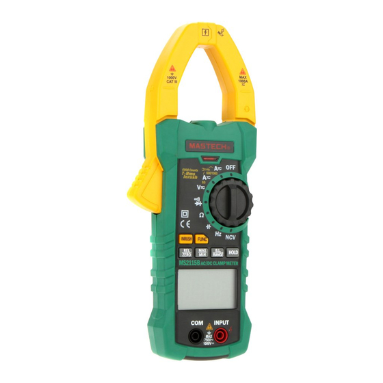
- Page 1 MS2115B DUAL DISPLAY DIGITAL CLAMP METER OPERATION MANUAL 1000 V 1000A CAT III 6000 Counts T - Rms 600/1000 Inrush INRUSH FUNC B.L. HOLD RANGE ZERO MS2115B AC/DC CLAMP METER INPUT...
-
Page 2: Table Of Contents
CONTENTS CONTENTS 1. Safety Information ........1 4.6 Relative Measurement ......17 .........18 4.7 Surge Measurement 1.1 Preparation ..........1 4.8 Automatic Power-Off .........18 1.2 Usage ............2 4.9 Measurement Preparation ......18 1.3 Mark .............3 4.10 Current Measurement ......19 1.4 Maintenance ..........4 ......20 4.11 Voltage Measurement 2. -
Page 3: Safety Information
1.1.4 Probe should be in good condition. Before use, 1. Safety Information please check whether the probe insulation is damaged and whether the metal wire is bare. Warning 1.1.5 Use the probe table provided with the meter to Please particularly note that inappropriate use may ensure safety. -
Page 4: Mark
1.2.11 Do not use the meter in explosive gas, vapor or 1.4 Maintenance dusty environment. 1.4.1 Don't try to open the meter bottom case to adjust 1.2.12 If you find any abnormal phenomena or failure or repair. Such operations only can be made by on the meter, stop using the meter immediately. -
Page 5: Part Name
(3) Clamp head light (4) Rotary switch (5) Input Socket (6) NCV indicator (7) Trigger 6000 Counts (8) Key 600/1000 T - Rms Inrush (9) Display (10) USB communication socket INRUSH FUNC B.L. HOLD RANGE ZERO MS2115B AC/DC CLAMP METER INPUT... -
Page 6: Lcd Display
2.2 Rotary Switch, Button And Input Jack Alternating Current, direct current AC, DC Description Diode, on/off B.L/RANGE button: used for measuring range switch Automatic measuring range mode AUTO or back light control. Maximum/minimum measurement FUNC button: used for measuring function switch. MAX /MIN HOLD button: data hold. -
Page 7: Specification
3.2 Technical Indicators 3. Specifications 3.2.1 True RMS Zero Input Characteristic Each year, at a minimum, the meter should be 3.2.1.1 For measuring non-sinusoidal wave signals, recalibrated when temperature is 18°C ~ 28°C and use the true RMS measuring method, which relative humidity is less than 75%. - Page 8 3.2.3 DC Current Note: Measuring range Accuracy In the small voltage measuring range, the probe is not Resolution connected with the circuit to be tested, and the meter 0.01A may have fluctuating readings, This is normal and ±(2.5% reading + 8 digits) 600A 0.1A caused by the meter's high sensitivity, and does not...
- Page 9 3.2.7 Frequency 3.2.7.3 Through Hz grade: 3.2.7.1 Clamp head measuring frequency (through Measuring range Accuracy Resolution grade A): 60.00Hz 0.01Hz Measuring range Accuracy Resolution 600.0Hz 0.1Hz 60.00Hz 0.01Hz 6.000kHz ±(1.5% reading + 5 digits) 600.0Hz 0.1Hz ±(0.3% reading + 5 digits) 60.00kHz 0.01kHz 6.000kHz...
-
Page 10: Operating Guidance
3.2.10 Circuit Continuity Test 4. Operating Guidance Measuring range Resolution Function 4.1 Reading Hold If the resistance of circuit to In the process of measurement, if reading hold is be measured is less than required, then press “HOLD” key to release 0.1Ω... -
Page 11: Maximum/Minimum Measurement Choice
4.4 Maximum/Minimum Measurement Choice minus reference value. ie. REL△(current reading) = Input value - Reference value. The main display 1) Press “MAX/MIN” key to enter MAX mode and save shows input value - reference value, and the alternate measurement maximum value. Press “MAX/MIN” display shows reference value. -
Page 12: Current Measurement
4.11 Voltage Measurement 4.10 Current Measurement 1) Insert black probe to COM jack, insert red probe to 1) Rotary switch is placed to position A. At this time, INPUT jack, choose appropriate measuring range. the meter is in AC current measurement state. 2) Place transfer switch to AC voltageV position. -
Page 13: Diode Test
4.13 Resistance Test 4.15 Circuit Continuity Test 1) Insert black probe to COM jack, insert red probe to 1) Insert black probe to COM jack, insert red probe to INPUT jack. INPUT jack. 2) Place measuring range switch to Ω position. -
Page 14: Usb Communication
2) To get accurate reading, connect the lead to be tested 4.19 USB Communication at the center of current clamp. 1) Install MS2115B communication software and USB 3) In the manual measuring range mode, when LCD only driver in the PC (see PC software operation manual shows “OL”, which indicates over-range, choose... -
Page 15: Replace Probe
If the probe is damaged, such as a bare metal wire, replace the probe. 6. Accessories Level: 1000V 10A One pair Probe Operation Manual 1 PC 6F22 9V carbonic Battery 1 PC acid battery USB communication 1 PC cable MS2115B communication 1 PC software CD HYS007032...
Need help?
Do you have a question about the MS2115B and is the answer not in the manual?
Questions and answers