Table of Contents
Advertisement
Quick Links
Advertisement
Table of Contents

Related Manuals for Kobold TUR Series


Summary of Contents for Kobold TUR Series
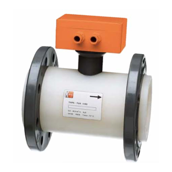
- Page 1 Operating Instructions Turbine Wheel Flow Meter Model: TUR...
-
Page 2: Table Of Contents
Pressure Loss Diagram ................14 EU Declaration of Conformance ..............15 Manufactured and sold by: Kobold Messring GmbH Nordring 22-24 D-65719 Hofheim Tel.: +49(0)6192-2990 Fax: +49(0)6192-23398 E-Mail: info.de@kobold.com Internet: www.kobold.com page 2 TUR K02/0618... -
Page 3: Note
2. Note Please read these operating instructions before unpacking and putting the unit into operation. Follow the instructions precisely as described herein. The devices are only to be used, maintained and serviced by persons familiar with these operating instructions and in accordance with local regulations apply- ing to Health &... -
Page 4: Regulation Use
4. Regulation Use The TUR series units are used for the flow measurement of liquids. These units are furnished with the following outputs. Pulse Output Rotary motion of the turbine a signal with a specific frequency. Analogue Output In order to transduce the measured flow data, an analogue output is available, (DIN IEC 381) with 0-20 mA, 4-20 mA or 0-10 V (see Type-tag). -
Page 5: Mechanical Connection
6. Mechanical Connection Before Installation: Please ensure that the actual flow-rate corresponds with the measured volume within measuring range of the unit. Measuring range is printed on the type-tag. Attention! Exceeding the measuring range (more than 20 %) may result in damage to bearings and considerable measurement- errors. -
Page 6: Electrical Connection
7. Electrical Connection Warning! Please ensure that the supply voltage to your instrument conforms to the value given on the equipment label. Ensure that the power lines are not active. With units without transducer, connect the cable-ends with your power supply and load, as is shown in the figure. -
Page 7: Electrical Commissioning
8. Electrical Commissioning The instrument is delivered ready to operate. On Instruments with transducers the electronic is matched and calibrated with the transducer. Calibration screws are not intended for customer's use. An attempt to calibrate the unit by the customer would require a new calibration to restore factory accuracy (rendered by the firm, on payment). -
Page 8: Mechanical Commissioning
9. Mechanical Commissioning To avoid pressure shocks, the flow medium should run slowly into the unit. Warning! Pressure shocks from solenoid valves, ball valves or similar devices may lead to breakage of the instrument (water hammer). In the operating condition, it must be checked that the instrument housing is continuously filled with the flow medium. -
Page 9: Technical Information
11. Technical Information Measuring accuracy: ±1% of f. s. Viscosity range: for low-viscosity media Max. operating temperature: 60 °C (PVC version) 70 °C (PVDF version) Max. operating pressure: PN 10 Protection type: IP 65 PVC version PVDF version (1) Fitting PVDF (2) Bearing cross bars PVDF... -
Page 10: Order Codes
ADI electronics Display: bar graph and 5 digit digital display Analogue output: (0)4-20 mA, 0-10 V 2 switching outputs: relay/changeover contact max. 250 V /5 A resistive load max. 30 V /5 A Setting: via 4 buttons Power supply: 100...240 V ±... -
Page 11: Materials
Measuring sensor with ADI electronics – Order details (example: TUR-2025 M000) Connection Measuring Model designation Evaluating electronics PVC flange range water wetted parts Transmitter Nominal dia. [m³/h] PVDF Supply Output ..M0.. = 230 V ..40 = 4-20 mA 0.2-5.0 ..M2.. = 24 V ..00 = 0-20 mA TUR-2025... -
Page 12: Dimensions
14. Dimensions *with PNP or NPN Sensor page 12 TUR K02/0618... - Page 13 TUR with compact Description Dimension A TUR-..25 TUR-..50 TUR-..80 TUR-..10 TUR with ADI-, Gxxx- and Exxx electronics Description Dimension A TUR-..25 TUR-..50 TUR-..80 TUR-..10 TUR K02/0618 page 13...
-
Page 14: Pressure Loss Diagram
15. Pressure Loss Diagram page 14 TUR K02/0618... -
Page 15: Eu Declaration Of Conformance
16. EU Declaration of Conformance We, KOBOLD Messring GmbH, Hofheim-Ts, Germany, declare under our sole responsibility that the product: Turbine Wheel Flow Meter Model: TUR-1 which relates to this certificate, conforms to the standards listed below: EN 60947-5-2:2007 + A1:2012... -
Page 16: Kobold Messring Gmbh
We, KOBOLD Messring GmbH, Hofheim-Ts, Germany, declare under our sole responsibility that the product: Turbine Wheel flow Meter Model: TUR-2 to which this declaration relates is in conformity with the standards noted below: EN 61000-6-3:2011 Electromagnetic compatibility (EMC) - Part 6-3: Generic standards - Emission...
Need help?
Do you have a question about the TUR Series and is the answer not in the manual?
Questions and answers