Moxa Technologies MC-1100 Series Hardware User Manual
Hide thumbs
Also See for MC-1100 Series:
- Quick installation manual (11 pages) ,
- Quick installation manual (16 pages)

Related Manuals for Moxa Technologies MC-1100 Series


Summary of Contents for Moxa Technologies MC-1100 Series
- Page 1 MC-1100 Series Hardware User’s Manual Edition 3.0, November 2017 www.moxa.com/product © 2017 Moxa Inc., All rights reserved.
- Page 2 MC-1100 Series Hardware User’s Manual The software described in this manual is furnished under a license agreement and may be used only in accordance with the terms of that agreement. Copyright Notice © 2017 Moxa Inc., All rights reserved. Trademarks The MOXA logo is a registered trademark of Moxa Inc.
-
Page 3: Table Of Contents
Table of Contents Introduction ............................1-1 Package Checklist ..........................1-2 Product Features ..........................1-2 MC-1100 Hardware Specifications ......................1-2 Hardware Block Diagram ........................1-4 Hardware Introduction ........................2-1 Appearance ............................2-2 MC-1111 ............................ 2-2 MC-1121 ............................ 2-3 MC-1112 ............................ 2-4 MC-1122 ............................ - Page 4 Upgrading the BIOS .......................... 4-18 Regulatory Approval Statement ......................A-1 Configuring the Serial Interface ......................B-1 Overview ............................B-2 Configuring the Serial Interface Mode ....................B-2 Examples............................C-1 Serial Interface ..........................C-2 Digital Input/Output ..........................C-3 Watchdog ............................C-5 Power Control ............................ C-5...
-
Page 5: Introduction
Introduction Moxa’s MC-1100 Series DIN-rail mountable, fanless, x86 embedded computers are based on the Intel® Atom™ E3800 Series processor, feature the most reliable I/O design to maximize connectivity, and support wireless modules (Wi-Fi/3G/LTE), making them suitable for a diverse range of communication applications. -
Page 6: Package Checklist
MC-1100 Hardware User’s Manual Introduction Package Checklist • MC-1100 embedded computer • Terminal block to power jack converter • DIN-rail mounting kit • Quick installation guide (printed) • Warranty card NOTE: Please notify your sales representative if any of the above items are missing or damaged. Product Features MC-1100 embedded computers support the following features: •... - Page 7 MC-1100 Hardware User’s Manual Introduction Serial Interface Serial Standards: 2 or 4 RS-232/422/485 ports, software-selectable (DB9 male) Serial Communication Parameters Data Bits: 5, 6, 7, 8 Stop Bits: 1, 1.5, 2 Parity: None, Even, Odd, Space, Mark Flow Control: RTS/CTS, XON/XOFF, ADDC® (automatic data direction control) for RS-485 Baudrate: 50 bps to 115.2 kbps Serial Signals RS-232: TxD, RxD, DTR, DSR, RTS, CTS, DCD, GND...
-
Page 8: Hardware Block Diagram
MC-1100 Hardware User’s Manual Introduction Standards and Certifications Safety: UL 60950-1 Hazardous Environments: Class 1 Division 2* EMC: EN 55032, EN 55024 EMI: CISPR 32, FCC Part 15B Class A EMS: IEC 61000-4-2 ESD: Contact: 6 kV; Air: 8 kV IEC 61000-4-3 RS: 80 MHz to 1 GHz: 10 V/m IEC 61000-4-4 EFT: Power: 2 kV;... -
Page 9: Hardware Introduction
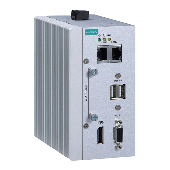
Hardware Introduction The MC-1100 Series embedded computers are compact, well-designed, and rugged enough for industrial applications. LED indicators help you monitor performance and identify trouble spots, multiple serial ports allow you to connect different devices for wireless operation, and the reliable and stable hardware platform lets you devote your attention to developing your applications. -
Page 10: Appearance
MC-1100 Hardware User’s Manual Hardware Introduction Appearance MC-1111 Top View Front View... -
Page 11: Mc-1121
MC-1100 Hardware User’s Manual Hardware Introduction MC-1121 Top View Front View Rear View... -
Page 12: Mc-1112
MC-1100 Hardware User’s Manual Hardware Introduction MC-1112 Top View Front View Rear View... -
Page 13: Mc-1122
MC-1100 Hardware User’s Manual Hardware Introduction MC-1122 Top View Front View Rear View... -
Page 14: Dimensions In Mm (Inch)
MC-1100 Hardware User’s Manual Hardware Introduction Dimensions in mm (inch) MC-1111... -
Page 15: Mc-1121
MC-1100 Hardware User’s Manual Hardware Introduction MC-1121... -
Page 16: Mc-1112
MC-1100 Hardware User’s Manual Hardware Introduction MC-1112... -
Page 17: Mc-1122
MC-1100 Hardware User’s Manual Hardware Introduction MC-1122... -
Page 18: Led Indicators
MC-1100 Hardware User’s Manual Hardware Introduction LED Indicators LED Name Status Function Green Power is on and computer is function normally. Power Power is off. Yellow Blinking: Data is being transmitted. Storage 1 (CFast) No data transmission. Storage 2 Yellow Blinking: Data is being transmitted. -
Page 19: Hardware Connection Description
Hardware Connection Description In this chapter, we show how to connect the embedded computers to the network and to various devices. The following topics are covered in this chapter: Installing a Wireless Module Installing the MC-1100 Wiring Requirements ... -
Page 20: Installing A Wireless Module
MC-1100 Hardware User’s Manual Hardware Connection Description Installing a Wireless Module Both the MC-1121 and MC-1122 models have been provided with an in-built mini-PCIe socket for installing a wireless module. To install a wireless modules in your MC-1100 computer, do the following: STEP 1: Loosen the six screws on the right panel and the two screws on the bottom panel. - Page 21 MC-1100 Hardware User’s Manual Hardware Connection Description STEP 3: Insert the wireless module card at an angle. STEP 4: Push the wireless module card down. STEP 5: Secure the wireless module card with the 2 screws included in the package. STEP 6: Connect the antenna cable connector to the wireless module card.
-
Page 22: Installing The Mc-1100
MC-1100 Hardware User’s Manual Hardware Connection Description STEP 8: (Optional) You can install external 3G, 4G, and Wi-Fi antennas from Moxa to increase the wireless coverage. Contact a Moxa sales representative for details. An MC-1100 computer with external antennas installed is shown here. Installing the MC-1100 DIN-Rail Mounting The MC-1100 comes with a DIN-rail mounting kit for installing the computer on a DIN rail. - Page 23 MC-1100 Hardware User’s Manual Hardware Connection Description Removal: STEP 1: To unmount the MC-1100, pull down the latch provided at the base of the mounting kit with a screwdriver. STEPS 2: Slightly pull the MC-1100 forward and lift up to detach it from the DIN rail.
-
Page 24: Wiring Requirements
MC-1100 Hardware User’s Manual Hardware Connection Description Wall or Cabinet Mounting (DNV) Use the optional wall-mounting kit to install the MC-1100 on to a wall. NOTE The wall mounting kit can be purchased separately. STEP 1: Attach the wall-mounting brackets to the rear side of the MC-1100 by using two screws per bracket. -
Page 25: Connecting The Power
MC-1100 Hardware User’s Manual Hardware Connection Description ATTENTION Safety First! Be sure to disconnect the power cord before installing and/or wiring your MC-1100. Wiring Caution! Calculate the maximum possible current in each power wire and common wire. Observe all electrical codes dictating the maximum current allowable for each wire size. - Page 26 MC-1100 Hardware User’s Manual Hardware Connection Description MC-1111 MC-1121 MC-1112 MC-1122...
-
Page 27: Connecting To A Network
MC-1100 Hardware User’s Manual Hardware Connection Description Connecting to a Network To connect the MC-1100 computer to a network, connect a network cable to the embedded computer’s Ethernet port and connect the other end of the cable to your Ethernet network. When the cable is properly connected, the LEDs on the embedded computer’s Ethernet port turns on to indicate a valid connection. -
Page 28: Connecting To A Serial Device
MC-1100 Hardware User’s Manual Hardware Connection Description MC-1112 MC-1122 10/100 Mbps 1000 Mbps ETx+ TRD(0)+ ETx- TRD(0)- ERx+ TRD(1)+ – TRD(2)+ – TRD(2)- ERx- TRD(1)- – TRD(3)+ – TRD(3)- Connecting to a Serial Device Use a serial cable to connect your serial device to the embedded computer’s serial port. Serial ports P1 to P2 have male DB9 connectors and can be configured for RS-232, RS-422, or RS-485 communication. - Page 29 MC-1100 Hardware User’s Manual Hardware Connection Description MC-1121 MC-1112 MC-1122 3-11...
-
Page 30: Installing An Sdhc/Sdxc Card (Mc-1111 And Mc-1121 Only)
MC-1100 Hardware User’s Manual Hardware Connection Description DB9 Male Port RS-232/422/485 Pinouts RS-232 RS-422 RS-485 (4-wire) RS-485 (2-wire) TxDA(-) TxDA(-) – TxDB(+) TxDB(+) – RxDB(+) RxDB(+) DataB(+) RxDA(-) RxDA(-) DataA(-) – – – – – – – – – Installing an SDHC/SDXC Card (MC-1111 and MC-1121 Only) The MC-1100 has an SD slot for storage expansion. -
Page 31: Connecting To A Usb Device
MC-1100 Hardware User’s Manual Hardware Connection Description Connecting to a USB Device The MC-1100 is provided with one USB 3.0 host with type-A connector on the right-side panel and two USB 2.0 hosts with type-A connectors on the front panel. These ports can be used to connect to an external flash disk or hard drive. -
Page 32: Di/Do
MC-1100 Hardware User’s Manual Hardware Connection Description DI/DO The MC-1121 comes with a 4-channel digital input and a 4-channel digital output that connect through a terminal block connector. The pin assignments and wiring methods are shown in the diagrams below: MC-1121 MC-1122 RTC Battery Replacement... -
Page 33: Bios Setup
BIOS Setup In this chapter, we describe the BIOS settings for the MC-1100 embedded computer. The BIOS is a set of input/output control routines for peripherals, which can be used to initialize the basic peripheral settings. The BIOS firmware helps boot the system before the operating system is loaded. The BIOS setup allows the user to modify the system configuration for basic input/output peripherals. -
Page 34: Entering The Bios Setup
MC-1100 Hardware User’s Manual BIOS Setup Entering the BIOS Setup To enter the BIOS setup utility, press the F2 key while the system is booting up. The main BIOS Setup screen appears with the following options: • Continue: Continue to boot up Boot Manager: Select the device to boot up •... -
Page 35: Main Information
MC-1100 Hardware User’s Manual BIOS Setup Main Information The main page shows basic system information, such as the model name, BIOS version, and CPU type. NOTE The “Processor Type” varies depending on the product model. Advanced Settings The Advanced screen appears when you select “Advanced” from the main menu. -
Page 36: Boot Configuration
MC-1100 Hardware User’s Manual BIOS Setup Boot Configuration This screen allows you to configure the initial status of the Numlock key when the computer boots up. Options: On (default), Off PCI Express Configuration PCIE PORT 1 Speed Configure PCIe Port1 Speed Options: Auto, Gen1 and Gen2 PCIE PORT 2 Speed Configure PCIe Port2 Speed... -
Page 37: Usb Configuration
MC-1100 Hardware User’s Manual BIOS Setup USB Configuration USB Port #0 Enable or Disable USB port 0; if disabled, the system won’t detect when a USB device is plugged in. Option: Enabled (default), Disabled USB Port #1 Enable or Disable USB port 1; if disabled, the system won’t detect when a USB device is plugged in. Option: Enabled (default), Disabled USB Port #2 Enable or Disable USB port 2;... -
Page 38: Sd Configuration (Mc-1111 And Mc-1121 Only)
MC-1100 Hardware User’s Manual BIOS Setup SD Configuration (MC-1111 and MC-1121 Only) SDR25 Capability Support for SD Card Set Input/output timing for SDR25 mode. Option: Enabled (default), Disabled DDR50 Capability Support for SD Card Set Input/output timing for DDR50 mode. Option: Enabled (default), Disabled... -
Page 39: Miscellaneous Configuration
MC-1100 Hardware User’s Manual BIOS Setup Miscellaneous Configuration Power ON after Power Failure This setting allows you to configure whether or not the computer automatically reboot after a system crash. When set to ON, the computer will automatically reboot after a system crash; when set to OFF, it won’t automatically reboot after a system crash. -
Page 40: Sata Configuration
MC-1100 Hardware User’s Manual BIOS Setup DO-3 Level This item allows you set the DO 3 as high or low. Options: High (default), Low SATA Configuration Chipset SATA Mode Select SATA mode Options: AHCI (default), IDE SATA Speed Select SATA Speed Options: Gen1 (default), Gen2... -
Page 41: Console Redirection
MC-1100 Hardware User’s Manual BIOS Setup Console Redirection Console Serial Redirect When the Console Redirection Function is enabled, the console information will be output to both the HDMI monitor and through the serial port. Options: Disabled (default), Enabled ACPI SPCR Table This table is used to indicate whether a serial port or a non-legacy UART (Universal Asynchronous Receiver/Transmitter) interface is available for use with Microsoft Windows Emergency Management Services (EMS). -
Page 42: Hardware Monitor
MC-1100 Hardware User’s Manual BIOS Setup Hardware Monitor This screen allows you to view voltage levels, system temperature, and CPU temperature. Note that the voltage values vary depending on the model. The temperature readings shown on the screen are within ±5% of the actual readings. However, the temperature readings are only valid when the ambient temperature is above 0°C. -
Page 43: Security Settings
MC-1100 Hardware User’s Manual BIOS Setup Load SMART RECOVERY Default This setting allows you to load the Smart Recovery default value. Refer to the Smart Recovery Website at http://www.moxa.com/product/Smart-Recovery.htm for details Options: Yes (default), No Security Settings This screen allows you to configure a supervisor password. Set Supervisor Password This setting allows you set the supervisor password. -
Page 44: Power Settings
MC-1100 Hardware User’s Manual BIOS Setup Power Settings The screen allows you to configure power settings. Wake on LAN This setting allows you to wake the system over the LAN from a remote host. Options: Enabled (default), Disabled. 4-12... -
Page 45: Auto Wake On S5
MC-1100 Hardware User’s Manual BIOS Setup Auto Wake on S5 This setting allows you to configure the computer to wake from the S5 (Soft Off) state where the power supply remains engaged but is not supplying power to all other parts of the system. You can set the auto-wake on S5 schedules for the system to perform a soft-reboot at specific times. -
Page 46: Power State 2 For Vcc & Vnn
MC-1100 Hardware User’s Manual BIOS Setup Power State 2 for VCC & VNN This setting allows you to enable/disable CPU core voltage (VCC) and graphics core voltage (VNN) rails for low-power scenarios in SOC S0 state. Options: Enabled (default), Disabled. Boot Settings The screen allows you to configure boot settings. -
Page 47: Add Boot Options
MC-1100 Hardware User’s Manual BIOS Setup Add Boot Options This setting allows you to add boot order options for new boot devices and removable devices, such as a USB drive. Options: Last (default), First, Auto USB Boot This setting allows you to enable or disable the USB boot function. Options: Enabled (default), Disabled Boot Delay Time This setting allows you to configure the delay time to enter a hot key during POST. -
Page 48: Efi
MC-1100 Hardware User’s Manual BIOS Setup Adjust boot order settings for an EFI device. Exit Settings The screen shows the various options to exit from the BIOS setup utility. 4-16... -
Page 49: Exit Saving Changes
MC-1100 Hardware User’s Manual BIOS Setup Exit Saving Changes This option allows you to exit the BIOS setup utility and save the values you have just configured. Options: Yes (default), No Save Change Without Exit This option allows you to save changes without exiting the BIOS setup utility. Options: Yes (default), No Exit Discarding Changes This option allows you to exit without saving that changes that might have been made to the BIOS. -
Page 50: Upgrading The Bios
MC-1100 Hardware User’s Manual BIOS Setup Upgrading the BIOS This section describes how to upgrade the BIOS. WARNING An improper BIOS upgrade process may permanently damage the computer. We strongly recommend that you contact Moxa technical support for assistance to obtain all the necessary tools and the most up-to-date advice before attempting to upgrade the BIOS on any Moxa device. - Page 51 MC-1100 Hardware User’s Manual BIOS Setup Step 3: Run the Upgrade Program on the MC-1100 Computer 1. Reboot the computer, and press F2 during the booting process to display the Boot Manager. 2. Select USB Disk as the first boot source and press [Enter] to continue. 3.
- Page 52 MC-1100 Hardware User’s Manual BIOS Setup 5. The upgrade program will run automatically. Wait until the procedure is complete. ATTENTION Do NOT remove the power supply during a BIOS upgrade. C:\> MC-1100>MC-1100S10.exe Option: -bios –all -nv Please do not remove the AC power! Insyde H20FFT (Flash Firmware Tool) Version (SEG) 100.00.07.20 Copyright(c) 2012 –...
-
Page 53: Regulatory Approval Statement
Regulatory Approval Statement This device complies with part 15 of the FCC Rules. Operation is subject to the following two conditions: (1) This device may not cause harmful interference, and (2) this device must accept any interference received, including interference that may cause undesired operation. -
Page 54: Configuring The Serial Interface
Configuring the Serial Interface In this chapter, we describe how to configure the MC-1100 embedded computer’s serial interface. The following topics are covered in this appendix: Overview Configuring the Serial Interface Mode... -
Page 55: Overview
MC-1100 Hardware User’s Manual Configuring the Serial Interface Overview The MC-1100’s COM1 and COM2 serial ports support the following serial modes: RS-232, 2-wire RS-485, and 4-wire RS-422/485. Configuring the Serial Interface Mode Complete the following steps to configure the serial interface mode: 1. - Page 56 MC-1100 Hardware User’s Manual Configuring the Serial Interface 3. Select the serial interface mode for the port from the Mode dropdown box. 4. Click OK.
-
Page 57: Examples
Examples In this chapter, we provide examples to illustrate how to use the MC-1100 computer for a variety of applications. The following topics are covered in this appendix: Serial Interface Digital Input/Output Watchdog Power Control... - Page 58 MC-1100 Hardware User’s Manual Examples Serial Interface 1. Download the MC-1100 Utility Package from: https://www.moxa.com/product/MC-1100_Series.htm 2. Copy the following files from the utility package to a folder on your MC-1100. mxsp.dll: \examples\MC-1100-W7E-example\3.lib\mxsp\x64\ sysinfo.dll: \examples\MC-1100-W7E-example\3.lib\mxsp\x64\ sysinfo.sys: \examples\MC-1100-W7E-example\3.lib\mxsp\x64\ sysinfoX64.sys: \examples\MC-1100-W7E-example\3.lib\mxsp\x64\ mxGeneralIo.dll: \examples\MC-1100-W7E-example\3.lib\MxGeneralIo\x64\ UartMode.exe: \examples\MC-1100-W7E-example\x64\Release\ 3.
-
Page 59: Digital Input/Output
MC-1100 Hardware User’s Manual Examples 5. Type 1 to display the current serial interface settings. Digital Input/Output 1. Download the MC-1100 Utility Package from: https://www.moxa.com/product/MC-1100_Series.htm 2. Copy the following files from the MC-1100 Utility Package to a folder on your MC-1100. mxdgio.dll: \examples\MC-1100-W7E-example\3.lib\mxdgio\x64\ mxGeneralIo.dll: \examples\MC-1100-W7E-example\3.lib\MxGeneralIo\x64\ DIO.exe: \examples\MC-1100-W7E-example\x64\Release\... - Page 60 MC-1100 Hardware User’s Manual Examples 4. Type 4 to display the current DI and DO values. 5. Type 3 to set the DOUT port number, and then follow the onscreen instructions. 6. Type 4 to check if the port value was set correctly.
-
Page 61: Watchdog
MC-1100 Hardware User’s Manual Examples Watchdog 1. Download the MC-1100 Utility Package from: https://www.moxa.com/product/MC-1100_Series.htm 2. Copy the following files from the MC-1100 Utility Package to a folder on your MC-1100. mxdwg.dll: \examples\MC-1100-W7E-example\3.lib\mxdwg\x64\ mxGeneralIo.dll: \examples\MC-1100-W7E-example\3.lib\MxGeneralIo\x64\ Watchdog.exe: \examples\MC-1100-W7E-example\x64\Release\ 3. To prevent the system from rebooting, press [Enter] at least once every 10 seconds; otherwise, the system will reboot automatically. - Page 62 MC-1100 Hardware User’s Manual Examples 4. Type 1 to display the current power status. 5. Type 2 and follow the onscreen instructions to set the power value. When you set the power value to 0, the power turns off. When you set the power value to 1, the power turns on.
Need help?
Do you have a question about the MC-1100 Series and is the answer not in the manual?
Questions and answers