
Related Manuals for Moxa Technologies DA-681A Series


Summary of Contents for Moxa Technologies DA-681A Series
- Page 1 DA-681A Series Embedded Computer Hardware User’s Manual Edition 1.0, November 2015 www.moxa.com/product © 2015 Moxa Inc. All rights reserved.
- Page 2 DA-681A Series Embedded Computer Hardware User’s Manual The software described in this manual is furnished under a license agreement and may be used only in accordance with the terms of that agreement. Copyright Notice © 2015 Moxa Inc. All rights reserved.
-
Page 3: Table Of Contents
Table of Contents Introduction ............................1-1 Overview ............................1-2 Model Descriptions and Package Checklist ....................1-2 Comparison of DA-Series Models ....................1-2 Optional Accessories ........................1-3 Expansion Modules (can be purchased separately) ................1-3 Optional Accessories (can be purchased separately) ................ 1-3 Appearance ............................ - Page 4 Discard Changes ........................3-11 Upgrading the BIOS .......................... 3-11 Safety Installation Instructions ......................A-1 RTC Battery Warning ........................... A-1 Fuse Warning ............................. A-1 Rack mount Warning ........................... A-1 Regulatory Statement Approval ......................B-1...
-
Page 5: Introduction
Introduction Thank you for purchasing the DA-681A series x86-based industrial ready-to-run embedded computer. This manual introduces the hardware installation, connector interfaces, and BIOS setup of the DA-681A. For software configuration and management, please refer to the user’s manual for your operating system. -
Page 6: Overview
Introduction Overview The Moxa DA-681A Series x86-based rack-mount embedded computers are designed for control, monitoring, data acquisition, and protocol conversion applications. With its robust design, the DA-681A is suitable for industrial automation applications, including power automation, transportation, and oil and gas. -
Page 7: Optional Accessories
DA-681A Series Hardware Introduction Each model is shipped with following standard items: • DA-681A rackmount computer • Rackmount kit • Documentation CD or DVD • Quick installation guide (printed) • Warranty card Optional Accessories Expansion Module Support Accessories Model Name... -
Page 8: Appearance
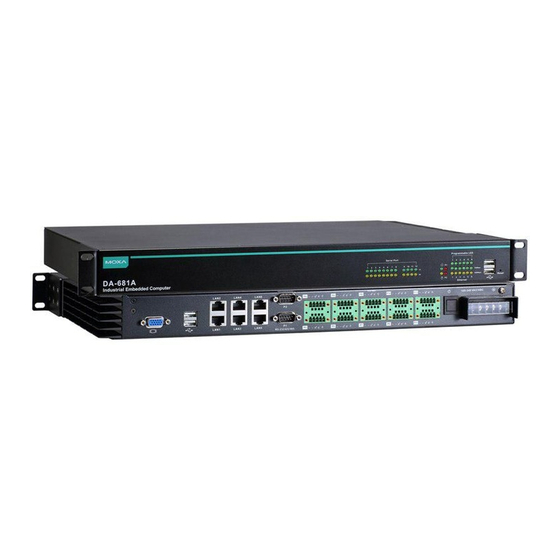
DA-681A Series Hardware Introduction Appearance Front View Rear View- DA-681A-DPP & DA-681A-DPP-T Rear View- DA-681A-SP Dimensions... -
Page 9: Features
DA-681A Series Hardware Introduction Features The DA-681A Basic System has the following features: • IEC 61850-3, IEEE 1613, and IEC 60255 compliant for power substation automation systems (DPP and DPP-T models only) • 3rd Gen Intel® Core™ Celeron 1047UE 1.4 GHz CPU •... -
Page 10: Hardware Specifications
DA-681A Series Hardware Introduction Hardware Specifications Computer CPU: 3rd Gen Intel® Core™ Celeron 1047UE 1.4 GHz OS: Linux Debian 8 (pre-installed) W7E available by CTOS System Chipset: Intel HM65 BIOS: 64 Mbit Flash BIOS, PCI Plug & Play, ACPI System Memory: 8 GB capacity, 2 GB for Linux pre-installed; 1 slot of DDR3-1066/1333 SO-DIMM SDRAM Expansion Bus: PCI/104 onboard (DPP models only) USB: 4 USB 2.0 ports, system bootable, type A connector... - Page 11 DA-681A Series Hardware Introduction Physical Characteristics Housing: SECC sheet metal (1 mm) Weight: 4.5 kg Dimensions: 440 x 315 x 45 mm (17.32 x 12.40 x 1.77 in), 19 inch 1U height Mounting: Standard 19-inch rackmount Environmental Limits Operating Temperature: SP Models: -25 to 55°C (-13 to 131°F)
-
Page 12: Hardware Installation
Hardware Installation The DA-681A Series of embedded computers are compact and rugged, making them suitable for industrial applications. The LED indicators allow users to monitor performance and identify trouble spots quickly, and multiple ports are provided for connecting a variety of different devices. The DA-681A embedded computers come with a reliable and stable hardware platform that lets you devote the bulk of your time to application development. -
Page 13: Placement Options
DA-681A Series Hardware Hardware Installation Placement Options Desktop Place your DA-681A on a clean, flat, well-ventilated desktop. For better ventilation, leave some space between the DA-681A and other equipment. Do not place equipment or objects on top of the DA-681A, as this might damage the computer’s internal components. -
Page 14: Wiring Requirements
DA-681A Series Hardware Hardware Installation Step 3: Installing the DA-681A to a rack. Gently slide the DA-681A onto the rack, and then use the screws provided by the rack supplier to affix the computer to the rail, as shown in the pictures below. -
Page 15: Connecting The Power
DA-681A Series Hardware Hardware Installation ATTENTION Safety First! Be sure to disconnect the power cord before installing and/or wiring your device. Electrical Current Caution! Calculate the maximum possible current in each power wire and common wire. Observe all electrical codes dictating the maximum current allowable for each wire size. -
Page 16: Wiring The Power Inputs
DA-681A Series Hardware Hardware Installation Wiring the Power Inputs For SP Models AC Terminal DC Terminal... -
Page 17: For Dpp And Dpp-T Models
DA-681A Series Hardware Hardware Installation For DPP and DPP-T Models AC Terminal DC Terminal... -
Page 18: Power Input Wiring Description
DA-681A Series Hardware Hardware Installation Power Input Wiring Description Read the following section for a detailed power input wiring description. SP Model power input wiring description Terminal Number Description Note No function Line/DC+ is connected to the positive (+) terminal if the power Line/DC+ source is DC, or to the Line terminal if the power source is AC. -
Page 19: Reset Button
DA-681A Series Hardware Hardware Installation Reset Button Pressing the Reset button initiates a hardware warm reboot. The button plays the same role as a desktop PC’s reset button. After pressing the reset button, the system will reboot automatically. During normal use, you should NOT use the Reset Button. -
Page 20: Connecting To A Display
DA-681A Series Hardware Hardware Installation Connecting to a Display Your DA-681A embedded computer comes with a D-Sub 15-pin female connector to connect to the VGA monitor. Be sure to remove the power before you connect or disconnect the monitor cable. -
Page 21: Connecting A Serial Device
DA-681A Series Hardware Hardware Installation Connecting a Serial Device The DA-681A has two 3-in-1 RS/232/422/485 serial ports, and 10 RS-485 ports. When the cable is properly connected, the LEDs on the front panel will glow to indicate a proper connection. -
Page 22: Connecting The Irig-B Time Synchronization Device (For Dpp & Dpp-T Models Only)
DA-681A Series Hardware Hardware Installation The default IP addresses and netmasks of the Gigabit LAN ports are as follows: Default IP Address Netmask LAN 1 192.168.3.127 255.255.255.0 LAN 2 192.168.4.127 255.255.255.0 LAN 3 192.168.5.127 255.255.255.0 LAN 4 192.168.6.127 255.255.255.0 LAN 5 192.168.7.127... -
Page 23: Connecting To The Da-Irigb-B-S Series
DA-681A Series Hardware Hardware Installation Connecting to the DA-IRIGB-B-S Series ATTENTION To prevent damage to your system or the mother board, make sure that you turn off the embedded computer before installing the DA-IRIGB-B-S Series module. 1. Turn the embedded computer off. - Page 24 DA-681A Series Hardware Hardware Installation 5. Connect the cables by completing the following actions: a. Connect the 2-wire IRIG-B input signal cable. b. Connect the 4-wire IRIG-B output signal cable. c. Install the DB9 connectors on the rear panel of the embedded computer.
-
Page 25: Installing The Memory Module
DA-681A Series Hardware Hardware Installation Installing the Memory Module The DA-681A embedded computer supports one DDR3-1066/1333 SO-DIMM module with up to 8 GB. One 2 GB DDR3 SDARM memory module is pre-installed for Linux models. An SDRAM module is not included with the DA-681A-SP, DA-681A-DPP, and DA-681A-DPP-T barebones models. -
Page 26: Installing A Msata Card
DA-681A Series Hardware Hardware Installation Installing a mSATA Card The DA-681A embedded computer comes with a mSATA socket. To insert a mSATA card, follow these instructions. 1. Disconnect the DA-681A from its power source. 2. The DA-681A’s mSATA socket is located inside the DA-681A. Use a screwdriver to remove all the screws on the top cover of the DA-681A. -
Page 27: Installing A Sata Hard Disk / Solid State Disk
DA-681A Series Hardware Hardware Installation Installing a SATA Hard Disk / Solid State Disk The DA-681A embedded computer has one SATA connector for installing a SATA hard disk / Solid State Disk. To install a 2.5-inch SATA hard disk / Solid State Disk, follow these instructions. (The hard disk bracket is an optional accessory that can be purchased separately.) - Page 28 DA-681A Series Hardware Hardware Installation 6. Install the SATA hard disk / Solid State Disk in the hard disk bracket. 7. Connect the SATA cable and power cable to the hard disk / Solid State Disk. 8. Next, install the SATA hard disk / Solid State Disk and bracket in the DA-681A. Make sure the screws are firmly attached.
- Page 29 DA-681A Series Hardware Hardware Installation 9. Connect the SATA power cable to the computer. 10. Connect the SATA HDD/SSD signal cable to the computer. 11. Properly position the cables, as shown in the following figure. ATTENTION The SATA hard disk kit and cables are not included in the basic shipment of the DA-681A embedded computer.
-
Page 30: Installing A Usb Dongle Kit
DA-681A Series Hardware Hardware Installation Installing a USB Dongle Kit An optional USB Dongle Kit can be purchased separately for the DA-681A embedded computer for installing a USB Dongle tightly inside the computer. To install the USB dongle with the USB Dongle Kit, follow these instructions. - Page 31 DA-681A Series Hardware Hardware Installation 6. Install the USB Dongle Kit in the DA-681A. Make sure the screws are firmly attached and connect the USB cable to computer. 7. Install the USB Dongle in the Dongle bracket. Mini sized dongle...
-
Page 32: Bios Setup
BIOS Setup This chapter describes the BIOS settings of the DA-681A embedded computers. The BIOS is a set of input/output control routines for peripherals. The BIOS is used to initialize basic peripherals and helps boot the operating system before the operating system is loaded. The BIOS setup allows the user to modify the system configurations of these basic input/output peripherals. -
Page 33: Entering The Bios Setup
DA-681A Series Hardware BIOS Setup Entering the BIOS Setup To enter the BIOS setup utility, press the “F2” key while the system is booting up. The main BIOS Setup screen will appear. Four options will be available: Continue: Continue to boot up... -
Page 34: Main Information
DA-681A Series Hardware BIOS Setup The BIOS configuration screen will be shown when you enter SCU option. Refer to the following figure. Please note that the information for Processor Type will vary depending on the different models that you purchase. -
Page 35: Boot Configuration
DA-681A Series Hardware BIOS Setup Boot Configuration This item allows users to configure the default value of Numlock. Option: On (default), Off. HDC Configuration The host drive controller may be configured for IDE (legacy default) or AHCI mode. When the legacy IDE mode is selected, the following screen will appear. -
Page 36: Video Configuration
DA-681A Series Hardware BIOS Setup Serial ATA Port 0 to 2 This setting allows the user to display information about the installed drives. AHCI SALP Please note that AHCI SALP will only appear when AHCI mode is selected. This item allows you to enable aggressive link power management (SALP) in AHCI. -
Page 37: Chipset Configuration
DA-681A Series Hardware BIOS Setup IGD—DVMT Pre-Allocated This item allows you to configure pre-allocated memory capacity for the IGD. Pre-allocated graphics memory is invisible to the operating system. Options: 64 MB (default), 32 MB, 96 MB, 128 MB, 256 MB, 512 MB DVMT is a BIOS solution where “the optimum amount of memory is dynamically allocated and de-allocated as... -
Page 38: Hardware Monitor
DA-681A Series Hardware BIOS Setup Hardware Monitor This item allows you to view stats like CPU and system temperature, voltage levels, and other chipset information. Please note that the voltage values will vary depending on the different models, and there will be 5% tolerance for the temperature values. -
Page 39: Set Supervisor Password
DA-681A Series Hardware BIOS Setup Set Supervisor Password This item allows you set the supervisor password. Select and then enter the password, and then confirm the password again. To delete the password, enter Set Supervisor Password and then enter the old password; then, leave the new password fields blank, and press enter. -
Page 40: Boot Settings
DA-681A Series Hardware BIOS Setup Boot Settings The section allows users to configure boot settings. Boot Type This item allows you to enable/disable quick boot function. Options: Dual Boot Type (default), Legacy Boot Type, UEFI Boot Type. PXE Boot to LAN This item allows you to enable/disable PXE boot to LAN function. -
Page 41: Legacy
DA-681A Series Hardware BIOS Setup Legacy Normal Boot Menu This item allows you to configure the boot menu. Options: Normal (default), Advance Boot Type Order This item allows you to select the boot order. Use +/F5 (move up) or -/F6 (move down) to change values. -
Page 42: Load Optimal Defaults
DA-681A Series Hardware BIOS Setup Load Optimal Defaults This item allows you to revert to the factory default BIOS values. Options: Yes (default), No Load Custom Defaults This item allows you to load custom default values for the BIOS settings. - Page 43 DA-681A Series Hardware BIOS Setup 1. Start Rufus and select the USB device that you want to use as a bootable disk from the Device drop-down list. 2. Select MBR partition scheme for BIOS or UEFI computers to boot from a legacy BIOS or UEFI.
- Page 44 DA-681A Series Hardware BIOS Setup 3. When boot up finishes, DOS screen will show up. Go to the directory where the upgrade file is located. For example, if the upgrade file is stored in the DA681A folder, type cd DA681A C:\cd DA681A 4.
-
Page 45: Safety Installation Instructions
Safety Installation Instructions RTC Battery Warning CAUTION: There is a risk of explosion if battery is replaced by an incorrect type. Dispose of used batteries according to the instructions. Fuse Warning CAUTION: For continued protection against fire, replace only with same type and rating of fuse. Rack mount Warning The following or similar rack mount instructions are included with the installation instructions: (1) Elevated Operating Ambient: If installed in a closed or multi-unit rack assembly, the operating ambient... -
Page 46: Regulatory Statement Approval
Regulatory Statement Approval This device complies with part 15 of the FCC Rules. Operation is subject to the following two conditions: (1) This device may not cause harmful interference, and (2) this device must accept any interference received, including interference that may cause undesired operation.
Need help?
Do you have a question about the DA-681A Series and is the answer not in the manual?
Questions and answers