
Related Manuals for Moxa Technologies DA-682C Series


Summary of Contents for Moxa Technologies DA-682C Series
- Page 1 DA-682C Series Embedded Computer User’s Manual Version 1.0, October 2019 www.moxa.com/product © 2019 Moxa Inc. All rights reserved.
- Page 2 DA-682C Series Embedded Computer User’s Manual The software described in this manual is furnished under a license agreement and may be used only in accordance with the terms of that agreement. Copyright Notice © 2019 Moxa Inc. All rights reserved.
-
Page 3: Table Of Contents
Table of Contents Introduction ............................1-1 Overview ............................1-2 Model Descriptions and Package Checklist ....................1-2 Appearance ............................1-3 Dimensions ............................1-4 Features ............................1-4 Hardware Block Diagram ........................1-5 DA-682C Basic System ........................ 1-5 Hardware Specifications ........................1-5 Hardware Installation ........................2-1 Installing the Rackmount Ears ...................... - Page 4 Discard Changes ........................3-20 Enable AMT ............................3-21 Use AMT ............................3-24 Upgrading the BIOS .......................... 3-25 Safety Installation Instructions ......................A-1 1. RTC Battery Warning ........................A-1 2. Fuse Warning ..........................A-1 3. Rackmount Warning ........................A-1...
-
Page 5: Introduction
Introduction Thank you for purchasing a Moxa DA-682C industrial computer, a multi-functional embedded computer designed especially for IEC 61850-3 substation automation systems. This manual covers hardware installation, connector interfaces, and BIOS setup of the DA-682C. For software configuration and management, please refer to the user’s manual for your operating system. The following topics are covered in this chapter: ... -
Page 6: Overview
2U, 19-inch wide, rack mounted rugged enclosure. This robust, rack mountable design provides the hardened protection needed for industrial environment applications. Model Descriptions and Package Checklist The DA-682C Series includes the following models: • DA-682C-KL1-HH-T: Intel® Celeron® 3965U, 2C/2T, 2.2 GHz CPU, with 2x HDMI, 6 Gigabit LAN ports, 2 RS/232/422/485 3-in-1 serial port, 2 PS/2, 6 DI/2DO, 1 mSATA, 2 SATA, 6 USB, dual power, -40 to 70°C... -
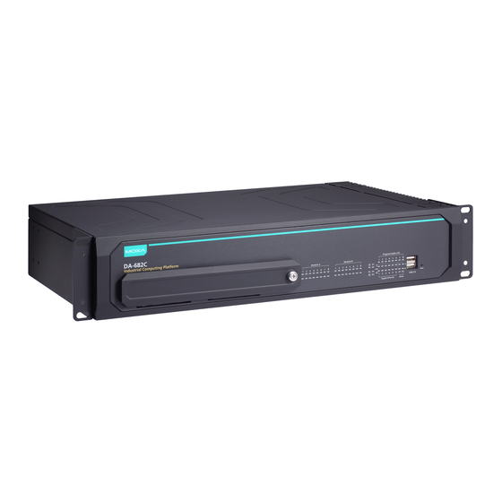
Page 7: Appearance
DA-682C Series Introduction Before installing the DA-682C computer, make sure the package contains the following items. If any of these items is missing or damaged, please contact your customer service representative for assistance. • DA-682C rackmount computer • Rackmount kit •... -
Page 8: Dimensions
DA-682C Series Introduction Dimensions Unit = mm (inch) Features The DA-682C computer has the following features: • IEC 61850-3, IEEE 1613, and IEC 60255 compliant for power substation automation systems • 7th Generation Intel® Core™ Processor • Built-in DDR4 memory slot; up to 32 GB capacity •... -
Page 9: Hardware Block Diagram
DA-682C Series Introduction Hardware Block Diagram DA-682C Basic System Hardware Specifications NOTE The latest specifications for Moxa’s products can be found at https://www.moxa.com. -
Page 10: Hardware Installation
Hardware Installation The DA-682C embedded computers are compact and rugged, making them suitable for industrial applications. The LED indicators allow users to monitor performance and identify trouble spots quickly, and multiple ports are provided for connecting a variety of different devices. The DA-682C embedded computers come with a reliable and stable hardware platform that lets you devote the bulk of your time to application development. -
Page 11: Installing The Rackmount Ears
DA-682C Series Hardware Installation Installing the Rackmount Ears The DA-682C computer comes with two rackmount kits that allow users to mount the computer on to a rack. Each rackmount kit includes the following items: a rackmount ear and four screws. -
Page 12: Wiring Requirements
DA-682C Series Hardware Installation Wiring Requirements The following common safety precautions should be observed before installing any electronic device: • Power wires and communication/signal wires should be routed through separate paths. If power and communication/signal wires must cross paths, make sure the wires are perpendicular at the intersection point. -
Page 13: Connecting The Power
DA-682C Series Hardware Installation Connecting the Power The DA-682C provides dual power inputs using a terminal block, which is located on the rear panel. Connect the power cord wires to the screws, and then tighten the screws. The Power LED will light up to indicate that power is being supplied to the DA-682C, after which the BIOS will initialize the flash disk module, causing the Storage LED to blink. -
Page 14: Grounding The Chassis
DA-682C Series Hardware Installation Grounding the Chassis There is a grounding connector located on the rear panel of the computer. Connect the connector to the chassis ground source. ATTENTION If protective earthing is used as a safeguard, the instructions shall require connection of the equipment protective earthing conductor to the installation protective earthing conductor (for example, by means of a power cord connected to a socket-outlet with earthing connection). -
Page 15: Reset Button
DA-682C Series Hardware Installation In addition, there is a power button on the rear panel, which allows users to power on the computer in case the computer is in the sleep or hibernate mode. Reset Button Pressing the Reset button initiates a hardware warm reboot. The button plays the same role as a desktop PC’s reset button. -
Page 16: Connecting To Displays
DA-682C Series Hardware Installation Information about each LED indicator is given in the following table. Color Description Power Green Power is on No power input Storage Yellow/Blinking Data is being written to or read from the storage unit Storage unit is idle... -
Page 17: Connecting Usb Devices
DA-682C Series Hardware Installation Connecting USB Devices The DA-682C comes with 2 USB 2.0 ports on the front panel and 3 USB 3.0 ports on the rear panel. The USB ports can be used to connect to other peripherals, such as flash drives for expanding the system’s storage capacity. -
Page 18: Serial Ports
DA-682C Series Hardware Installation 2. The USB Dongle Kit includes a USB plate and a screw. 3. Attach the USB device to the USB port inside the 4. Place the USB plate on the rail, and push down to DA-682C computer. -
Page 19: Gigabit Lan Ports
DA-682C Series Hardware Installation The ports use terminal blocks. Refer to the following table for the pin assignments: RS-232 RS-422 RS-485 RS-485 (4-wire) (2-wire) TxD(+) TxD(+) – TxD(-) TxD(-) – RxD(+) RxD(+) Data(+) RxD(-) RxD(-) Data(-) Gigabit LAN Ports The DA-682C has 6 Gigabit LAN ports. When a LAN cable is properly connected, the LEDs on the front panel will glow to indicate a proper connection. -
Page 20: Digital Inputs/Digital Outputs
DA-682C Series Hardware Installation Digital Inputs/Digital Outputs The DA-682C comes with six digital inputs and two digital outputs in a terminal block. Refer to the following figure for the location of the DI/DO connectors. For pin definitions and wiring methods, see the figures below. -
Page 21: Upgrading The Memory Module
DA-682C Series Hardware Installation Upgrading the Memory Module The DA-682C embedded computer supports 2 ECC registered DDR3 1333/1600 SODIMM modules, for up to 16 GB of memory (2 slots, each with 8 GB). To upgrade the SDRAM memory module, follow these instructions: 1. -
Page 22: Installing An Msata Storage Card
DA-682C Series Hardware Installation Installing an mSATA Storage Card The DA-682C embedded computer comes with an mSATA socket. To insert an mSATA storage card, follow these instructions. 1. Disconnect the DA-682C from its power source. 2. Unfasten the screws on the back of the computer, and then take off the upper cover. -
Page 23: Installing Sata Hard Disks
DA-682C Series Hardware Installation Installing SATA Hard Disks The DA-682C comes with two SATA slots that allow users to install two 2.5” SATA HDD/SSD in the computer. Follow these steps to install a SATA disk. 1. Unfasten the screw on the storage disk tray, and pull down the tray door. -
Page 24: Installing The Expansion Module
DA-682C Series Hardware Installation 5. There are two plastic rails inside the slot. Make sure to insert the storage tray into the rails. 6. Push the disk tray into the computer; make sure the storage tray has been successfully inserted. Use the same method to install another disk if necessary. -
Page 25: Bios Setup
BIOS Setup This chapter describes the BIOS settings of the DA-682C computer. The BIOS is a set of input/output control routines for peripherals, and is used to initialize system peripherals before the operating system is loaded. The BIOS setup allows the user to modify the system configurations of these peripherals’ basic input/output. The following topics are covered in this chapter: ... -
Page 26: Entering The Bios Setup
DA-682C Series BIOS Setup Entering the BIOS Setup To enter the BIOS setup utility, press the F2 while the system is booting up. The main BIOS Setup screen will appear. Five options will be available: Continue: Continue to boot up •... - Page 27 DA-682C Series BIOS Setup When you enter Setup Utility, a basic description of each function key is listed at the bottom of the screen. Refer to these descriptions to learn how to use them. General Help Select Item ↑/↓. F5/ F6...
-
Page 28: Main Page
DA-682C Series BIOS Setup Main Page The Main page displays basic system hardware information, such as model name, BIOS version, and CPU type. -
Page 29: Advanced Settings
DA-682C Series BIOS Setup Advanced Settings Select the “Advanced” option in the main menu to open the “Advanced Features” screen. NOTE The Active Management Technology is not supported in the DA-682C-KL1 and DA-682-KL3 models. -
Page 30: Boot Configuration
DA-682C Series BIOS Setup Boot Configuration This item allows users to configure the default value of Numlock. Options: On (default), Off. SATA Configuration The host drive controller can be configured for AHCI (default) or Intel RST Premium mode. - Page 31 DA-682C Series BIOS Setup Serial ATA Port This setting displays the information about the installed drives. SATA Port—HotPlug This item allows you to enable/disable hot-plugging capabilities (the ability to remove the drive while the computer is running) for installed storage drives.
-
Page 32: Intel® Rapid Storage Technology
DA-682C Series BIOS Setup Intel® Rapid Storage Technology Select Device Management on the BIOS main page and then select the Intel® Rapid Storage Technology option. -
Page 33: Cpu Configuration
DA-682C Series BIOS Setup CPU Configuration NOTE Hyper-Threading is not supported in the DA-682C-KL1 and DA-682C-KL3 models. Active Processor Cores This item indicates the number of cores to enable in each processor package. Hyper-threading This feature makes the processor resources work more efficiently, enabling multiple threads to run on each core. -
Page 34: Active Management Technology Support
DA-682C Series BIOS Setup Active Management Technology Support This item allows you to configure the Intel Active Management Technology. ® NOTE The DA-682C-KL3 model does not support this function. ME Unconfig on RTC Clear State Disabling this option will cause ME not to unconfigure on RTC clear. -
Page 35: Video Configuration
DA-682C Series BIOS Setup Video Configuration DVMT Pre-Allocated This item allows you to configure pre-allocated memory capacity for the IGD. Pre-allocated graphics memory is invisible to the operating system. Options: 12 M, 16M, 20M, 24M, 28M, 32M (default), 36M, 40M, 44M, 48M, 52M, 56M, 60M, 64M DVMT: The amount of video memory your computer has is dependent on the amount of pre-allocated memory set for your system plus the Dynamic Video Memory Technology (DVMT). -
Page 36: Chipset Configuration
DA-682C Series BIOS Setup Chipset Configuration This item allows you to configure the chipset settings. Power ON after Power Failure This item allows you to enable/disable the computer from automatically powering up after system power is re-enabled. Options: ON (default), OFF, Last State DO-0 Level This item allows users to set the DO 0 as high or low. -
Page 37: Sio Ite8786E
DA-682C Series BIOS Setup SIO ITE8786E This section allows users to configure serial port settings. Serial Port A This function allows users to configure the resources for serial port A. Disable: No resources Enable: User configures the resources Auto (default): EFI/OS chooses the resources Serial Port B This function allows users to configure the resources for serial port B. -
Page 38: Console Redirection
DA-682C Series BIOS Setup Hardware Monitor This item allows you to view stats such as CPU and system temperature, voltage levels, and other chipset information. Console Redirection When the Console Redirection Function is enabled, the console information will be output to both the HDMI monitor and through the serial port. -
Page 39: Security Settings
DA-682C Series BIOS Setup Security Settings This section allows users to configure security-related settings with a supervisor password and user password. NOTE These settings will only appear in computers that have the TPM module. Current TPM Device This item shows if the system has TMP device and its type. -
Page 40: Set Supervisor Password
DA-682C Series BIOS Setup Set Supervisor Password This item allows you to set the supervisor password. Select the Set Supervisor Password option and enter the password and confirm the password again. To delete the password, select the Set Supervisor Password option and enter the old password; leave the new password fields blank, and then press enter. -
Page 41: Power Settings
DA-682C Series BIOS Setup Enable: System will ask input password on post time. Disable: System will ask for the password to go to the setup utility. Config-Only: System will only ask for the password when you select the config (F2) option Power Settings The section allows users to configure power settings. -
Page 42: Power On Usb2 (Front Panel)
DA-682C Series BIOS Setup Power On USB2 (front panel) This item allows users to power on or power off the USB ports on the front panel. Options: Disabled, Enabled (default) Power On USB2 (built-in) This item allows user to powers on or power off the internal USB port inside the computer. -
Page 43: Network Stack
DA-682C Series BIOS Setup Network Stack It deploys an Internet Protocol (IP) stack. The IP stack provides an application library to open/close connections to remote devices and send/receive data between the remote devices. Options: Disabled (default), Enabled PXE Boot capability PXE Booting is booting a system over a network. -
Page 44: Exit Saving Changes
DA-682C Series BIOS Setup Exit Saving Changes This item allows you to exit the BIOS environment and save the values you have just configured. Options: Yes (default), No Save Change Without Exit This item allows you to save changes without exiting the BIOS environment. -
Page 45: Enable Amt
DA-682C Series BIOS Setup Enable AMT NOTE The AMT function is not supported for DA-682C-KL1 and DA-682C-KL3 models. To enter the BIOS setup utility, press the F2 while the system is booting up. The main BIOS Setup screen will appear. Five options will be available: 1. - Page 46 DA-682C Series BIOS Setup 3. Type the default password: admin 4. Type the new password. It must include both upper-case and lower-case characters, numbers, and special symbols. E.g., Admin’12. 5. Select Intel® AMT Configuration to enable remote access without a local user present for consent, select User Consent, and then select User Opt-in and change the value to None.
- Page 47 DA-682C Series BIOS Setup 6. Set static IP or DHCP by request. 7. Set Activate Network Access to enable remote access capability. 3-23...
-
Page 48: Use Amt
DA-682C Series BIOS Setup Use AMT The DA-682C’s AMT port is LAN1. You can use any of the available AMT tools to execute the remote management function. The easiest method is using a web browser. 1. Type the IP for your DA-682C that was configured in the AMT configuration with port 16992. The AMT logon screen will appear. -
Page 49: Upgrading The Bios
DA-682C Series BIOS Setup Upgrading the BIOS This section describes how to upgrade the BIOS. However, note that it is easy to permanently damage the computer when upgrading the BIOS. We strongly recommend that you contact Moxa’s technical support staff for assistance in order to obtain all the necessary tools and the most current advice before attempting to upgrade the BIOS on any Moxa device. - Page 50 DA-682C Series BIOS Setup 2. Right click on the USB disk then select “Format”. 3. Select “FAT32”, and click OK to start formatting. Step 2: Prepare the Upgrade File You must use the BIOS upgrade installation file to upgrade the BIOS. Contact Moxa’s technical department for assistance.
- Page 51 DA-682C Series BIOS Setup Step 3: Run the upgrade program on the Computer 1. Reboot the computer, and press F2 while booting up to go to the Boot Manager. If BIOS cannot recognize the USB drive as the boot devices, the USB drive could have no partition table. Use windows command line tool diskpart to rebuild the partition table.
- Page 52 DA-682C Series BIOS Setup 5. When the upgrade is finished, the computer will automatically reboot. You may check BIOS version on the Main page 6. If the system have more than one boot device, you will see more than one fsx (x means number) 7.
-
Page 53: Safety Installation Instructions
Safety Installation Instructions 1. RTC Battery Warning ATTENTION There is a risk of explosion if the wrong type of battery is used. To avoid this potential danger, always be sure to use the correct type of battery. Contact the Moxa RMA service team if you need to replace your battery.
Need help?
Do you have a question about the DA-682C Series and is the answer not in the manual?
Questions and answers