
Subscribe to Our Youtube Channel
Related Manuals for Moxa Technologies IA240


Summary of Contents for Moxa Technologies IA240
- Page 1 IA240 Hardware User’s Manual Edition 8.1, May 2018 www.moxa.com/product © 2018 Moxa Inc. All rights reserved.
- Page 2 IA240 Hardware User’s Manual The software described in this manual is furnished under a license agreement and may be used only in accordance with the terms of that agreement. Copyright Notice © 2018 Moxa Inc. All rights reserved. Trademarks The MOXA logo is a registered trademark of Moxa Inc.
-
Page 3: Table Of Contents
Wall Mounting (Optional) ......................1-7 Hardware Connection Description ......................1-8 Wiring Requirements ........................1-8 Connecting the Power ........................1-8 Grounding the IA240 ........................1-9 Connecting to the Network ......................1-9 Connecting to a Serial Device ....................... 1-9 Connecting to the Console Port ....................1-10 SD Interface .......................... -
Page 4: Introduction
IA240 Series ideal for your embedded applications. This manual introduces the hardware of the IA240 Series embedded computers. After a brief introduction of the hardware features, the manual focuses on installation and hardware configuration with device interfaces. -
Page 5: Overview
16 MB NOR Flash ROM and 64 MB SDRAM give you enough memory to run your application software directly on the IA240. As the dual LAN ports are built right into the Moxa ART ARM9 CPU, the IA240 is an ideal communication platform for Network Security applications. -
Page 6: Product Hardware Specifications
IA240 Hardware Introduction Product Hardware Specifications IA240 / IA240-T Moxa “ART” ARM9 32-bit CPU 192 MHz 64 MB Flash 16 MB Linux Auto-sensing 10/100 Mbps x 2 with built-in 1.5 KV magnetic isolation protection; RJ45 Connector Serial Ports RS-232/422/485 × 4, RJ45 Connector... -
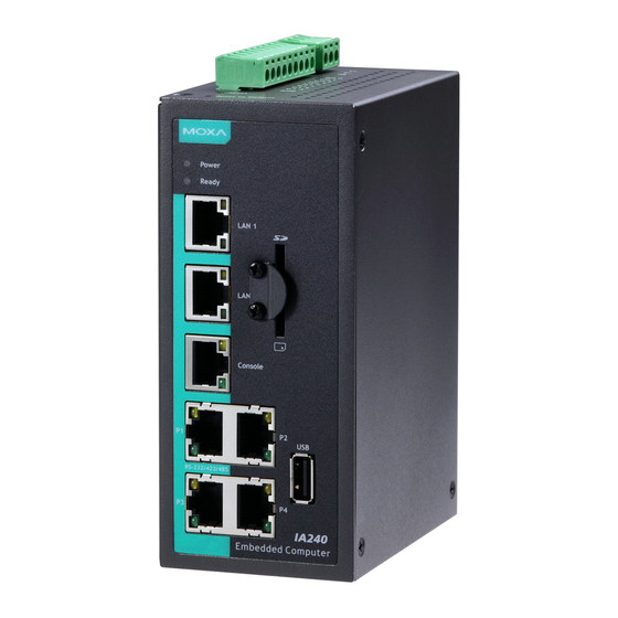
Page 7: Hardware Introduction
IA240 Hardware Introduction Hardware Introduction Appearance... -
Page 8: Dimensions
IA240 Hardware Introduction Dimensions LED Indicators The IA240 has 16 LED indicators on the front panel. Refer to the following table for information about each LED. LED Name Color Meaning Power Power is ON. Ready Green OS is ready and functioning normally (after booting up). -
Page 9: Real Time Clock
The aluminum DIN-Rail attachment plate is already attached to the product’s casing. To attach the plate to IA240, make sure that the stiff metal spring is facing the top of the IA240, as shown in the following figures. STEP1: Insert the top of the DIN-Rail into the slot STEP2: The DIN-Rail attachment unit will snap into just below the stiff metal spring. -
Page 10: Wall Mounting (Optional)
IA240 Hardware Introduction Wall Mounting (Optional) For some applications, you will find it convenient to mount IA240 on the wall, as depicted by the following illustrations. STEP 1: Remove the aluminum DIN-Rail attachment plate from IA240’s rear panel, and then attach the wall mount plates, as shown by the figures at the right. -
Page 11: Hardware Connection Description
Connecting the Power Connect the 12 to 48 VDC power line to the IA240’s terminal block. If the power is properly supplied, the Power LED will light up. The Ready LED will glow a solid green color when the operating system is ready (it may take 30 to 60 seconds for the operating system to boot up). -
Page 12: Grounding The Ia240
Connecting to the Network Connect one end of the Ethernet cable to one of the IA240’s 10/100M Ethernet ports (8-pin RJ45) and the other end of the cable to the Ethernet network. If the cable is properly connected, the IA240 will indicate a valid... -
Page 13: Connecting To The Console Port
Connecting to the Console Port The IA240’s console port is an 8-pin RJ45 RS-232 port. The port can be used to connect to the console utility from a remote console via a V90 or GPRS modem with PPP protocol. The pin definition is the same as for the serial ports (P1 to P4).
Need help?
Do you have a question about the IA240 and is the answer not in the manual?
Questions and answers