Advertisement
Available languages
Available languages
Quick Links
Setup Guide
Always wear safety glasses or eye shields
WARNING:
when assembling the snow thrower.
Handle Assembly
1. Carefully unfold the handle while guiding the speed
control rod over the tire before cutting the orange ties.
2. Raise the upper handle (A, Figure 1) to the operating
position.
NOTE: Make sure the Z fi ttings at the ends of the cables are
secured in the holes on the control levers. Make sure
the cables are not caught between the upper and lower
handle.
3. Insert two bolts (B) into lower holes and fasten with two
lock washers and wing knobs (C) or nuts (if equipped).
Tighten all four fasteners securely.
4. Use the supplied ties to secure the EZ Steer™ cable (if
equipped) to the left handle and the wire harness to the
right handle.
A
Figure 1
Install the Speed Control Rod
Attach the ball joint (D, Figure 2), located on the bottom end
of the speed control rod (E), to the shift yoke assembly (F)
with 5/16" lock washer (G) and 5/16" nut (H). Tighten nut
securely.
Copyright Briggs & Stratton Corporation
B
B
C
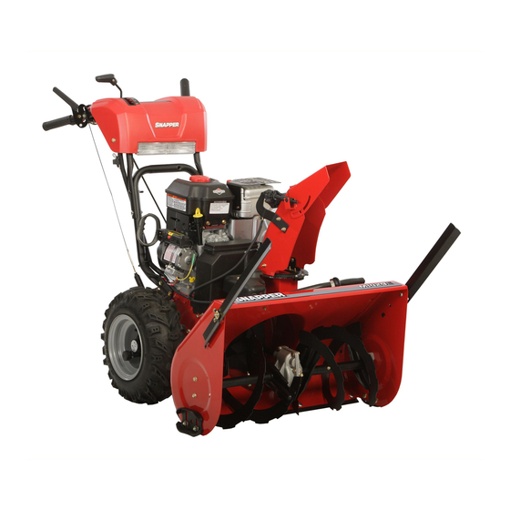
Dual Stage Snow Thrower
Mfg. No.
1695734, 1695735, 1695820, 1695821, 1695824, 1695825,
1695826, 1695827, 1695843, 1695853, 1695906, 1695908,
1695964
G
H
Figure 2
Install the Chute Control Rod
NOTE: Some models have the chute control already installed.
Models with an electric chute do not have a control rod.
1.
Insert the chute control handle (if equipped) through the
opening in the upper handle control panel.
2.
Insert the end of the chute control rod (
versal joint assembly (J) located next to the chute gear.
Secure with hair pin (K).
J
Figure 3
E
D
F
I) into the uni-
K
1739435 (Rev. B)
I
Advertisement

Related Manuals for Briggs & Stratton 1695734


Summary of Contents for Briggs & Stratton 1695734
- Page 1 5/16” lock washer (G) and 5/16” nut (H). Tighten nut securely. Copyright Briggs & Stratton Corporation Dual Stage Snow Thrower Mfg. No. 1695734, 1695735, 1695820, 1695821, 1695824, 1695825, 1695826, 1695827, 1695843, 1695853, 1695906, 1695908, 1695964 Figure 2 Install the Chute Control Rod NOTE: Some models have the chute control already installed.
- Page 2 Figure 4 NOTE: If the chute rotation is slow or binding, loosen the chute rotation screws (L, Figure 4) 1/4 turn. Install the Discharge Chute NOTE: Some models have the discharge chute already installed. Place discharge chute ( M, Figure 5) over tabs on chute ring (N) as shown.
- Page 3 CHECK OIL LEVEL Remove oil dipstick (Q, Figure 8). Check oil level. Oil level should be between FULL and ADD marks. Add oil if required (See Operator’s Manual). Reinstall oil dipstick. FULL Figure 8 Check the Tires Check tires for damage. Check the air pressure in the tires with an accurate gauge.
- Page 4 (F) avec une rondelle frein de 5/16 po (G) et un écrou de 5/16 po (H). Serrez l’écrou à fond.. Mfg. No. 1695734, 1695735, 1695820, 1695821, 1695824, 1695825, 1695826, 1695827, 1695843, 1695853, 1695906, 1695908, 1695964 Figure 2 INSTALLER LA TIGE DE COMMANDE CHUTE REMARQUE :Certains modèles sont munis d'une commande de...
- Page 5 Figure 4 REMARQUE : Si la rotation de la goulotte est lente ou grippée, desserrez les vis de rotation de goulotte (L, Figure 4) d’un 1/4 de tour. Placez la goulotte d’éjection ( pattes de l’anneau de goulotte (N) selon l’illustration. Attachez la goulotte d’éjection à...
-
Page 6: Vérification Des Pneus
VÉRIFIEZ LE NIVEAU D’HUILE 1. Retirez la jauge d’huile (Q, Figure 8). Vérifi ez le niveau d’huile. Le niveau d’huile doit être entre les marques PLEIN et AJOUTER. Réinstaller la jauge d'huile. FULL Figure 8 VÉRIFICATION DES PNEUS Vérifi ez les pneus pour dommage. Vérifi ez la pression d’air des pneus avec une jauge.