Table of Contents
Advertisement
Quick Links
Advertisement
Table of Contents
Troubleshooting

Related Manuals for KROHNE VFM 1091 I


Summary of Contents for KROHNE VFM 1091 I
- Page 1 4/2001 Vortex flowmeter Installation and Operating Instructions VFM 1091(I)
-
Page 2: Table Of Contents
Contents Part A System installation and start-up Description Installation in the pipe line 4 – 6 General Sandwich type to DIN 19205 / ANSI Flanged type to DIN 2501 / ANSI B16.5 (SCH-40) Temperature / Pressure Measurement for External Density Compensation Electrical connection Installation location and cable diameter Connection to power... - Page 3 Description of programme functions 7-23 Numerical order description 7-20 Functional order description 6.2.1 Physical units 6.2.2 Numerical format 6.2.3 Display 6.2.4 Flow range and meter size 6.2.5 Primary information 6.2.6 Application information 6.2.7 Internal Electronic Totalizer 6.2.8 Current (analog) output I 6.2.9 Pulse.
-
Page 4: Part A System Installation And Start-Up
Part A system installation and start-up 1. Description 2. Difference between inside diameters of primary head and pipeline DΝ Meter size of primary head in millimeters or Inches KRONHE MARSHALL vortex flowmeters operate on the Karman Φ vortex street principle to measure volumetric flow rate of gases /steam Inside diameter of primary head in millimeters Max. - Page 5 Flexible pipes or bellows may be used before the upstream and after the downstream in case the vibrations are too high. Pipe vibration limit is 0.2 g peak to peak up to 8-500 Hz crossover frequency. (which equals 0.75 mm) EXPANDER REDUCER 5.
-
Page 6: Sandwich Type To Din 19205 / Ansi
• In case of steam or compressed gas, a moisture separator may be used 2.3 Flanged type to DIN 2501 / ANSI B 16.5(SCH-40) 50D upstream of the meter if the dryness fraction is less than 95%. • For gases, a filter or strainer may be used to remove solid particles. •... -
Page 7: Electrical Connection
3.2 Connection to loop power supply 3. Electrical Connection • In case of functional extra low voltages (24VDC) protective separation in conformity with VDE 400 part 410, or equivalent 3.1 Installation Location & Cable diameter national standard, must be ensured. •... -
Page 8: Connection Between Vfs1000 (I) F And Vfc 091 F
3.3.3 Connection between VFS1091 & VFC 091F 3.3.4 Pulse out put • The pulse output is galvanically isolated from the 4-20mA current output and may be optionally grounded. • All functions and operating data are programmable; see Section 5, 6.1 6.2.9 •... -
Page 9: Part B Signal Converter Vfc 091
Part B Signal Converter VFC 091 5. Opening of the signal converter 5.1 General 5.1.1 Starting up signal converter When power is switched ON to signal converter it displays TEST, VFM, 1091 & Ver.x.x.x and then goes to measurement mode. In this initial sequence VFM 1091 (I) carries out self-diagnostics to check its own functiona1elements and loads the configuration data from non-volatile memory. -
Page 10: Operating And Check Elements
5.2 Operating & check elements The operating elements are accessible after removing the cover of the electronics section using the special wrench supplied. Caution Do not damage screw thread, never allow dirt to accumulate, and make sure it is well greased at all times. Display, 1st line Display, 2nd line Display, 3rd line... -
Page 11: Program Organization And Programming Chart
5.3 Program organization & programming chart 5.3.1 Menu levels The program for the signal converter consists of 5 levels. The 1 line of display will identify the menu levels during programming Fct 1.0 Fct 1.1.0 Actual Display Fct 1.1.1-1.1.4 OPERATION BASIS PARAM Fct 1.2.0 Fct 1.2.1-1.2.6... - Page 14 5.4 Program organization & function keys Function of keys in measurement mode: After power-on, the signal converter enters the normal measuring mode. Display shows the actual measured value of the parameter, units and arrow markers to identify parameter. A steady (non-blinking) display indicates that there are no errors in measuring mode. Use key to get the next parameter on display.
- Page 15 Using keys in programming mode Main menu level Submenu Data level Function level Option/Units Numerical values / strings Select main menu Select submenu or function select next Change flashing digit or Proposal Character Proposal Enter displayed Enter displayed submenu Shift flashing digit or Main menu (execute) function character position...
-
Page 16: Error Messages
5.5 Error messages 5.5.1 Error messages in Measurement mode Error message Type Description Corrective action required INTL ERR. nn Internal error in Switch off the power and try again. If the problem converter operation persists contact KHRONE MARSHALL service. NO SIGNAL No signal from No flow through the primary or Vortex sensor problem. -
Page 17: Description Of Programme Functions
The following units are available to choose from depending on Description of progra m function programming of. Fct. 1.1.1 MEAS. INST. for volumetric flow – Numerical order description • • • m3/hr m3/min UK Gal/Sec • • • Litre/hr Litre/min Litre/Sec This section describes all the functions which can be programmed locally. - Page 18 Fct. 1.2.1 FLOW UNITS for display Select NO DISPLAY if you don't want this parameter to be Select a unit in which flow rate is to be displayed from the following list displayed. of the available units, depending on programming of Fct.1.1.1 MEAS. INST.
- Page 19 Fct 1.3.3 P. WIDTH.LIM pulse width Fct. 3.0 INSTALL You can limit the duration of active pulse width of the Pulse output. You This is a main menu level whose submenus and their functions can choose - cover all installation-related functions which include: •...
-
Page 20: Functional Order Description
Fct. 3.2.3 TOT ON/OFF TOT. ON/OFF • • • cuft/hr cuft/min cuft/Sec Select option TOT. ON to start/restart totalizer and select option • • • US GAL/hr US GAL/min US GAL/Sec TOT.OFF to stop totalizer. Stopping totalizer means flow will not be •... -
Page 21: Numerical Format
6.2.2 Numerical format • Display of numerical values Real (i.e. fractional) values are displayed in the first line of the display consisting of 8 digits. Number is displayed in floating point format as far as possible, otherwise an exponent notation is used. See examples below. Floating format: 1234. -
Page 22: Primary Information
6.2.5 Primary information Primary data gives VFC 091 the basic information about the vortex primary sensor. Use Fct. 3.1.1 NOMINAL.DIA for specification of the nominal DIN/ANSI size and Fct. 3.1.2 K-FACTOR for the calibration factor of the primary. 6.2.6 Application information This is the data of process medium, it’s operating conditions and physical properties. -
Page 23: Coding Desired For Entry Into Programming Mode
Fct. 1.3.2 RANGE P Pulse output range value Pulse output is 0 Hz for 0 flow rate and a value (P ) equal to Q * RANGE P value. 100% 100% Example of pulses/unit volume or mass Full scale setting, Q 1000 Litre/hr (set via Fct. -
Page 24: Functions Through Hhc
6.2.13 Functions through HHC ® The special functions which are accessible only through HART communicator include Device Information and Multidrop Operation DEVICE INFORMATION This is used to identify the devices in the field. This is stored in the device and shown to you on request but has no effect on the functionality of the flowmeter. -
Page 25: Generic Online Menu Tree
6.2.14 Generic On-line Menu Tree 1.Present variable 1.Process variables 2.Percent Range 3.Analog Output 1.Test device 1.Self test 2.Diagnostics and 2.Loop Test Service 1.Apply values 3.Calibration 2.Enter Values 4.D/A Trim 1.Tag 1.Model 2.PV Snsr unit 2.Tag 3.Basic Setup 3.Date 3.Range Values 4.Descriptor 4.Device Info 5.Message... -
Page 26: Part C Functional Checks And Trouble Shooting Hints
Part C Function Checks and Trouble shooting hints 7. Functional checks This section describes some functional checks, which can be wire pin and earth should be >200 M ohm. Also short out performed without using any special equipment. It must be all three pins &... -
Page 27: Trouble Shooting Hints
SYMPTOM: Flow indicated responds to changes in flow 8. Trouble shooting hints but indicated value does not correspond to actual flow rate. It is assumed in this section that flowmeter has already been · Check programming of Fct.3.1.2 K-Factor which should be installed. -
Page 28: Part D Vfm 1091 (I) Ex
Part D VFM 1091 (I) Ex 9.2 Electrical connection 9. Description of the system VFM 1091 (I) Ex is a two wire loop powered flow transmitter VFM 1091 (I) Ex has two isolated Intrinsically safe circuits designed with electronic circuits incorporating Intrinsic safety 1. -
Page 29: Field Connection Diagram
10. Field connections diagram VFM 1091 (I) Ex 4-20 mA 4-20 mA Load 14 - 30V DC Hazardous Area 11. Name plate & certificates VFM 1091 (I) Ex. - Page 30 Certificate number of VFM 1091 (I) Ex. FM, CSA, PTB approvals are pending...
- Page 34 Range limit Calculation for Gases To obtain the operating density rx at the operating temperature and pressure the following equation is used n x Px x Tn r x , r n density of the gas at normal & operating conditions respectively. Pn, Px pressure of the gas in absolute units at normal operating conditions respectively.
- Page 35 Primary head VFS 1000 (I) Versions and meter sizes Pressure ratings see “Dimensions” Table (Note operating limits given in DIN 2501 and ANSI B 16.5) Sandwich design to ... DIN 19205 DN 25 to 150 ANSI 1” to 6” Flange connections to ...DIN 2501 DN 10S to 200 ANSI B 16.5 3/8”S TO 8”...
- Page 36 Diagram I Diagram II C / rn = 998.2 kg/m3 Pressure loss p for air 1.013 bar / 0 C (32 F) / n = 1.29 kg/m3 Pressure loss p for water 20 (14.69 psig/0 C/rn = 0.081 lbs/ft) (680 F/n = 62317 lbs/ft) p (psig) p(mbr)
- Page 37 Housing Material Die-cast aluminium Protection Category (EN 60529 / IEC 529) IP 65 & 67 (better than NEMA 4 and 4X) Frequency output (passive) scalable pulse output, max, load current 100 mA DC Max. pulse rate : 0.5 Hz Accuracy Linearity +/- 0.1 % of full scale range Power influence...
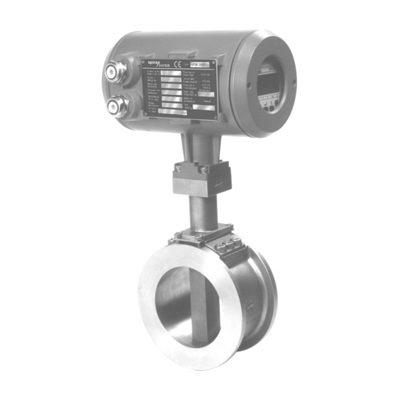
- Page 38 Dimensions and weight VHF 1091 (I) F Primary head flanged versions same as for VFM 1091 (I) K versions...
- Page 40 Dimensions and weights • 150 LBS AND 300 LBS PIPE METER MATING FLANGES WITH 7D&5D LOCATING PIPES • 1" AND 1.5" METER MATING FLANGES WILL 300LBS ONLY BUT PIPE MATING FLANGES CAN BE 150LBS/300LBS • Face to face distance for DN 100/4" units is 80 mm , so one to one replacement with the old design in this case is not possible.
- Page 41 Measuring principle The Vortex flowmeter is used for measuring the flow velocity of fluids in pipelines. The measuring principle is based on the development of a Karman Vortex shedding street in the wake of body built into the pipeline. In theory, this process enables measurements to be carried out in turbulent flows with a Reynolds number Re >...
- Page 42 Pipe for U/S, D/S Assembly Note : 1. Material : C.S. seamless Pipe (ASTM A106 GR-B) Unless specified dimentions are in mm...
- Page 43 R/F Flanges for U/S, D/S Assembly ANSI SW Note : Flanges as per the B16.5 Surface finish 32 to 63 um. Details to be stamped * Manufacturers Name or trademark * Flange Size * Flange Pressure Class * Material Designation * Heat Code Material : C.S., SA 516 Gr.
- Page 44 Recess Flanges for U/S, D/S Assembly ANSI, SW Note : Flanges Mating Dimentions as per ANSI B16.5 Surface finish 32 to 63 um. Details to be stamped * Manufacturers Name or trademark * Flange Size * Flange Pressure Class * Material Designation * Heat Code How to Stamp * Flange Recess Facing away operator...
- Page 45 R/F Flanges for U/S, D/S Assembly DIN Note : Flanges as per DIN 2501, Surface finish 32 to 63 um., Details to be stamped * Manufacturers Name or trademark * Flange Size * Flange Pressure Class * Material Designation * Heat Code How to Stamp * Flanges Facing operator Material : C.S.
- Page 46 Recess Flanges for U/S, D/S Assembly DIN, SW Note : Flange Mating Dimentions as per DIN 2501, Surface finish 32 to 63 um., Details to be stamped * Manufacturers Name or trademark * Flange Size * Flange Pressure Class * Material Designation * Heat Code How to Stamp * Flanges Recess Facing away operator Material : C.S.
- Page 47 Up Stream & Down Stream Assembly for SW Note : * One set of U/S Assly. and one set of D/S Assly is to be supplied * To be painted with heat resistant paint. * Flanges to welded off center. * Welding std.- Ad-Merkblatt B8 Material : C.S.
- Page 48 End Connection JIS Flanges for U/S, D/S pipes for SW VFM Note : Flanges as per JIS B2210 Surface finish 32 to 63 um. Details to be stamped * Manufacturers Name or trademark * Flange Size * Flange Pressure Class * Material Designation * Heat Code How to Stamp * Flange RF Facing operator...
- Page 49 U/S, D/S pipe Assly. with JIS 10K & ANSI Flanges Note : * One set of U/S Assly. and one set of D/S Assly is to be supplied * To be painted with heat resistant paint. * Flanges to welded off center. * Welding std.- Ad-Merkblatt B8 Material : C.S.
- Page 50 SW Vortex Flowmeter with U/S & D/S Note : · 150 LBS AND 300 LBS PIPE METER MATING FLANGES WITH 7D&5D LOCATING PIPES · 1" AND 1.5" METER MATING FLANGES WILL 300LBS ONLY BUT PIPE MATING FLANGES CAN BE 150LBS/300LBS ·...
- Page 51 Krohne Marshall Ltd. A -34 / 35 MIDC, 'H' Blk, Pimpri, Pune 411 018 Tel : 91 (0) 20-7470171 Fax : 91 (0) 20-7477049 After Office Hrs: 020-7477762 Subject to change without notice...
Need help?
Do you have a question about the VFM 1091 I and is the answer not in the manual?
Questions and answers