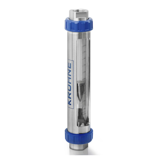
KROHNE VA40 Supplementary Instructions Manual
Variable area flowmeter equipment category ii 2 g with electrical components
Hide thumbs
Also See for VA40:
- Handbook (36 pages) ,
- Supplementary instructions manual (20 pages) ,
- Supplementary instructions manual (28 pages)
Table of Contents
Advertisement
Quick Links
VA40
VA40
VA40
VA40
Supplementary instructions
Supplementary instructions
Supplementary instructions
Supplementary instructions
Variable area flowmeter
Equipment category II 2 G with electrical components
Ex supplementary instructions
Ex supplementary instructions
Ex supplementary instructions
Ex supplementary instructions
© KROHNE 10/´2012 - 4002262401 MA VA40-Ex-II2G-AD R01 en
Advertisement
Table of Contents

Subscribe to Our Youtube Channel
Summary of Contents for KROHNE VA40
- Page 1 Supplementary instructions Supplementary instructions Supplementary instructions Supplementary instructions Variable area flowmeter Equipment category II 2 G with electrical components Ex supplementary instructions Ex supplementary instructions Ex supplementary instructions Ex supplementary instructions © KROHNE 10/´2012 - 4002262401 MA VA40-Ex-II2G-AD R01 en...
-
Page 2: Table Of Contents
4.1 General notes ......................... 11 4.2 Grounding and equipotential bonding................11 5 Operation 5.1 Start-up........................... 12 5.2 Operation ........................12 5.3 Electrostatic charge ....................... 12 6 Service 6.1 Maintenance ........................13 6.2 Dismantling ........................13 www.krohne.com 10/´2012 - 4002262401 MA VA40-Ex-II2G-AD R01 en... -
Page 3: Safety Instructions
SAFETY INSTRUCTIONS VA40 1.1 General notes These additional instructions apply to explosion-protected versions of the VA40/./../..-Ex variable area flowmeter with the designation II 2 G. They complement the Installation and Operating Instructions for the non-explosion protected versions. The information given in these Instructions contains only the data relevant to Category 2 explosion protection. -
Page 4: Device Description
1 Inserting limit switch 2 Version 21 Safety description code MS14: 1 Magnetic switch 2 Reed cartridge 14 without Limit switch with connected cable A - Limit switch with terminal box (standard) www.krohne.com 10/´2012 - 4002262401 MA VA40-Ex-II2G-AD R01 en... -
Page 5: Marking
9 PED-data 10 Design data: Temperature & pressure rating Marking Limit switch TG21 1 Type 2 Manufacturer 3 Ex data 4 KROHNE website 5 Built-in components 6 Observe Operation and Installation manual 10/´2012 - 4002262401 MA VA40-Ex-II2G-AD R01 en www.krohne.com... - Page 6 5 KROHNE website 6 Electrical connection data 7 Ex data Marking Limit switches MS14A 1 Type 2 Manufacturer 3 PTB number 4 Year made 5 Electrical connection data 6 Ex data 7 KROHNE website www.krohne.com 10/´2012 - 4002262401 MA VA40-Ex-II2G-AD R01 en...
-
Page 7: Flammable Products
The flowmeters are designed in category II 2G according to EN 60079-0 and EN 60079-11 for use in zone 1. 2.6 Protection types The circuits of the limit switches and of the electronic signal output are designed in Type of protection "Intrinsic Safety", Category ”ia“ and ”ib“ respectively. 10/´2012 - 4002262401 MA VA40-Ex-II2G-AD R01 en www.krohne.com... -
Page 8: Ambient Temperature / Temperature Classes
The maximum medium and ambient temperature is -20°C...+85°C / -4°F...+185°F. These values may be limited by the information contained in the installation and operating instructions. The maximum values listed in the installation and operating instructions must be taken into consideration. www.krohne.com 10/´2012 - 4002262401 MA VA40-Ex-II2G-AD R01 en... -
Page 9: Electrical Data
Built-in limit switch MS14 may only be connected to separate intrinsically safe circuits with the following maximum values: [mA] When connecting to intrinsically safe circuits, take into consideration the following maximum values per circuit for the energy stores. [nF] [µH] 10/´2012 - 4002262401 MA VA40-Ex-II2G-AD R01 en www.krohne.com... -
Page 10: Installation
The manufacturer is not liable for any damage resulting from improper use or use other than the intended purpose. This applies in particular to hazards due to insufficient corrosion resistance and suitability of the materials in contact with product. www.krohne.com 10/´2012 - 4002262401 MA VA40-Ex-II2G-AD R01 en... -
Page 11: Electrical Connections
The location of the ground connection on the back rail is shown below. This connection only ensures electrostatic grounding of the device and does not meet the requirements for equipotential bonding. Grounding connection 1 10/´2012 - 4002262401 MA VA40-Ex-II2G-AD R01 en www.krohne.com... -
Page 12: Operation
When dust-free gases or liquids are measured, the flow rate should not exceed 5 times the nominal flow rate. The max. allowable working pressure PS printed on the type nameplate is to be noted. The conductivity of the medium must be min. 1000pS/m. www.krohne.com 10/´2012 - 4002262401 MA VA40-Ex-II2G-AD R01 en... -
Page 13: Service
In the case of environmentally critical or hazardous products, appropriate safety precautions • must be taken with regard to residual liquids in the measuring unit. New gaskets have to be used when re-installing the device in the piping. • 10/´2012 - 4002262401 MA VA40-Ex-II2G-AD R01 en www.krohne.com... - Page 14 SERVICE VA40 www.krohne.com 10/´2012 - 4002262401 MA VA40-Ex-II2G-AD R01 en...
- Page 15 SERVICE VA40 10/´2012 - 4002262401 MA VA40-Ex-II2G-AD R01 en www.krohne.com...
- Page 16 • Measuring systems for the marine industry Head Office KROHNE Messtechnik GmbH Ludwig-Krohne-Str. 5 47058 Duisburg (Germany) Tel.:+49 (0)203 301 0 Fax:+49 (0)203 301 10389 info@krohne.de The current list of all KROHNE contacts and addresses can be found at: www.krohne.com...


Need help?
Do you have a question about the VA40 and is the answer not in the manual?
Questions and answers