Table of Contents
Advertisement
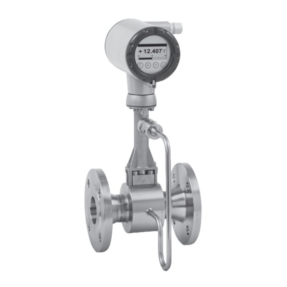
VFC 200
VFC 200
VFC 200
VFC 200
Supplementary Instructions
Supplementary Instructions
Supplementary Instructions
Supplementary Instructions
Signal converter for vortex flowmeters
Description of PROFIBUS interface
Description of PROFIBUS interface
Description of PROFIBUS interface
Description of PROFIBUS interface
PROFIBUS PA:
PROFIBUS PA:
PROFIBUS PA:
PROFIBUS PA:
PROFIBUS device with MBP Physical Interface and PA Profile 3.02 (2.0.2_/_190111)
The documentation is only complete when used in combination with the relevant
documentation for the standard flowmeter.
© KROHNE 06/2019 - 4005059401 - AD VFC200 PB-PA R01 en
Advertisement
Table of Contents

Related Manuals for KROHNE VFC 200


Summary of Contents for KROHNE VFC 200
- Page 1 PROFIBUS PA: PROFIBUS device with MBP Physical Interface and PA Profile 3.02 (2.0.2_/_190111) The documentation is only complete when used in combination with the relevant documentation for the standard flowmeter. © KROHNE 06/2019 - 4005059401 - AD VFC200 PB-PA R01 en...
-
Page 2: Table Of Contents
CONTENTS VFC 200 1 Safety instructions 1.1 Scope of the document..................... 3 1.2 Scope of delivery....................... 3 1.3 Special notes ........................3 2 PROFIBUS PA 2.1 Software history ....................... 4 2.2 System configuration of PROFIBUS PA network ............. 5 2.3 Electrical connection for PA signal converter ..............6 2.4 Technical data........................ -
Page 3: Safety Instructions
SAFETY INSTRUCTIONS VFC 200 1.1 Scope of the document These instructions are supplementary to the standard product documentation of the signal converter. The details depicted therein, in particular the safety information are valid and should be adhered to. The present supplementary instructions provide additional information for the devices when being operated and connected to PROFIBUS. -
Page 4: Profibus Pa
PROFIBUS PA VFC 200 2.1 Software history Issued Signal converter Application program System integration Mth./ Hardware Firmware Hardware Software Driver Version Model name year 01/19 Signal 2.0.2_/_190111 Simatic HW Config KR014541.GSD VFC200 (MBP) converter PCS7 manuf. Rev.1 with MBP other... -
Page 5: System Configuration Of Profibus Pa Network
PROFIBUS PA VFC 200 2.2 System configuration of PROFIBUS PA network The following diagram shows a typical instrumentation with PROFIBUS PA devices with MBP interface in hazardous and non-hazardous locations, including connections of conventional devices (e.g. with 4...20 mA signals) in a PROFIBUS network. -
Page 6: Electrical Connection For Pa Signal Converter
PROFIBUS PA VFC 200 2.3 Electrical connection for PA signal converter INFORMATION! The wiring between the device and the PROFIBUS PA bus is independant of polarity. The signal converter PROFIBUS PA with MBP (Manchester Coded Bus Powered) interface will operate without an additional power supply connected. -
Page 7: Technical Data
PROFIBUS PA VFC 200 2.4 Technical data Hardware Type PROFIBUS MBP interface according to IEC 61158-2 with 31.25 kbits/s; voltage mode [MBP = Manchester Coded Bus Powered] Connection Independent of polarity at electrical connection Base current 16 mA Yes, separate fault disconnection electronics provided (FDE = Fault Disconnection Electronics) 6 mA (fault current = max. -
Page 8: Profibus Pa Profile Implementation
PROFIBUS PA VFC 200 2.5 PROFIBUS PA Profile implementation The PROFIBUS PA Profile 3.02 defines standardised parameters and functions for PROFIBUS devices used for process control. It describes a PROFIBUS device as a function block application, i.e. parameters and functions are grouped into different blocks. In the Vortex PROFIBUS device... -
Page 9: Ident. Number Selector
PROFIBUS PA VFC 200 2.7 Ident. number selector Within a PROFIBUS network the type of a PROFIBUS slave is identified by its Ident. Number which is unique for this slave type. The PROFIBUS PA device supports two different Ident. numbers. Therefore it can be installed for different use cases. When the Ident. number is changed the behaviour of the device concerning the cyclic data transfer is changed;... - Page 10 PROFIBUS PA VFC 200 Manufacturer specific Ident. number (4541 hex) This setting provides complete functionality of the PROFIBUS PA device. All Function Blocks are available for cyclic data transfer. Device specific diagnosis information is transferred in addition to the Profile diagnosis.
- Page 11 PROFIBUS PA VFC 200 INFORMATION! During network configuration the user has to define which function block outputs of the signal converter should be transferred cyclically to the master. This is performed by a bus configuration tool (e.g. "HW- Config" for PC S7 from Siemens). This tool offers specific functions as follows: 1.
-
Page 12: Summary
PROFIBUS PA VFC 200 2.8 Summary The following table shows a summary of the supported combinations of the PROFIBUS device with MBP Physical Interface and PA Profile 3.02: Ident. Number Selector Ident. GSD File Status Number Automatic adaptation mode 4541 KR014541.GSD... -
Page 13: Commissioning / Operation
COMMISSIONING / OPERATION VFC 200 3.1 Configuration of cyclic data transfer During network configuration the user has to select which function block input/output data shall be transferred between the PROFIBUS master and the PROFIBUS slave. Network configuration will be done using one of the GSD files described before. During configuration a functional... - Page 14 COMMISSIONING / OPERATION VFC 200 Formula: Formula: Formula: Formula: (Exponent – 127) value = (-1) * (1 + Mantissa) (129 – 127) value = (-1) * (1 + 2 value = 1 * 4 * (1 + 0.5 + 0.25 + 0.125) value = 7.5...
- Page 15 COMMISSIONING / OPERATION VFC 200 The coding of the status value depends on the active status and diagnosis mode. It is described in the following tables. Condensed Status Condensed Status Condensed Status Condensed Status The "Condensed Status" codes have been defined to allow easier decoding of the information provided by the PROFIBUS devices.
- Page 16 COMMISSIONING / OPERATION VFC 200 Quality Quality substatus Limits = ok = update event = advisory alarm = critcal alarm = initiate fail safe (not provided by signal converter) = maintenance required = maintenance demanded = function check Table 3-5: Coding for "Status = good (Non Cascade)"...
- Page 17 COMMISSIONING / OPERATION VFC 200 Classic Status Classic Status Classic Status Classic Status The "Classic Status" is implemented to provide compatibility to systems which are not configured for "Condensed Status". The coding is shown in the following table: Quality Quality substatus...
- Page 18 COMMISSIONING / OPERATION VFC 200 Quality Quality substatus Limits = ok = update event = active advisory alarm = active critcal alarm = unacknowledged update event = unacknowledged advisory alarm = unacknowledged critical alarm = initiate fail safe = maintenance required Table 3-10: Coding for "Status = good (Non Cascade)"...
-
Page 19: Output Data
COMMISSIONING / OPERATION VFC 200 3.2.2 Output data Output data is transferred from the master to the PROFIBUS device to control the totalizers and to transmit measuring values to the PROFIBUS device. Behaviour and coding is described by the following tables. -
Page 20: Diagnosis
COMMISSIONING / OPERATION VFC 200 Format of SP (Set Point) Output data • 4 byte float value (for details on float format and status format refer to on page • 1 byte status value (for details on float format and status format refer to... - Page 21 COMMISSIONING / OPERATION VFC 200 Ident_Number violation Ident. Number Selector was modified while cyclic data transfer was active. To clear this message perform one of the following actions: • Reset Ident. Number Selector to its former setting • Stop cyclic data transfer •...
- Page 22 COMMISSIONING / OPERATION VFC 200 F – Sensor Sensor is defective and not able to measure. Related output values are invalid. Typically a repair or replacement of the device is required. Check sensor / cabling / 4 - restart the device – if the error still occur send back the device to the manufacturer with an indication of the error.
- Page 23 COMMISSIONING / OPERATION VFC 200 Config. - Operation Info Runtime data failure Runtime execution failure SE - not connected SE - Reset SE - Cyclic data failure SE - Diagnosis failure SE - Parameter update failure SE - not supported...
- Page 24 "Event group" will occur. "Single events" occurred can be displayed by using the VFC 200 display menu and/or by using the VFC 200 PROFIBUS DTM or the VFC 200 the VFC 200 display menu and/or by using the VFC 200 PROFIBUS DTM or the VFC 200...
- Page 25 COMMISSIONING / OPERATION VFC 200 Displaying "Single events" currently existing using the VFC 200 PROFIBUS EDD: Displaying "Single events" currently existing using the VFC 200 PROFIBUS EDD: Displaying "Single events" currently existing using the VFC 200 PROFIBUS EDD: Displaying "Single events" currently existing using the VFC 200 PROFIBUS EDD: Enter Menu "Diagnostics →...
-
Page 26: Mapping Of Diagnosis_Extension Bits Into Diagnosis Bits If "Condensed Status And Di- Agnosis" Handling Selected
COMMISSIONING / OPERATION VFC 200 3.3.1 Mapping of DIAGNOSIS_EXTENSION bits into DIAGNOSIS bits if "Condensed Status and Diagnosis" handling selected DIAGNOSIS_EXTENSION (Condensed) DIAGNOSIS (Condensed) Event group 24: C - Process Event group 25: C - Configuration Event group 26: C - Electronics... - Page 27 COMMISSIONING / OPERATION VFC 200 Corresponding DIAGNOSIS bit is set to 1 if status occured If "Function Check" selected (Display C6.4.4.2 or DTM .. / EDD ..) If "Maintenance Request" selected (Display C6.4.4.2 or DTM .. / EDD ..) If "Out of Specification" selected (Display C6.4.4.2 or DTM .. / EDD ..) If "Failure"...
-
Page 28: Mapping Of Diagnosis_Extension Bits Into Diagnosis Bits If "Classic Status And Diagno- Sis" Handling Selected
COMMISSIONING / OPERATION VFC 200 3.3.2 Mapping of DIAGNOSIS_EXTENSION bits into DIAGNOSIS bits if "Classic Status and Diagnosis" handling selected DIAGNOSIS_EXTENSION (Condensed) DIAGNOSIS (Classic) Event group 24: C - Process Event group 25: C - Configuration Event group 26: C - Electronics... -
Page 29: Variable "Event Groups
COMMISSIONING / OPERATION VFC 200 Corresponding DIAGNOSIS bit is set to 1 if status occured Event Group 13: is fixed to "Information" Event Group 8: will not be displayed within PROFIBUS Diagnosis / Diagnosis_Extension Event Group 9: will not be displayed within PROFIBUS Diagnosis / Diagnosis_Extension How to read the mapping table above: •... - Page 30 COMMISSIONING / OPERATION VFC 200 if condensed status and diagnosis condensed status and diagnosis handling selected: condensed status and diagnosis condensed status and diagnosis "F" Failure diagnosis: DIA_MAINTENANCE_ALARM (Maintenance alarm (40)) status: BAD - maintenance alarm OR BAD - process related "S"...
-
Page 31: Filtering Of "Single Events
Filtering of "Single events" will only be possible if using the VFC 200 PROFIBUS DTM (in conjunction with PACTware) or the VFC 200 PROFIBUS EDD (in conjunction with SIMATIC PDM). -
Page 32: Profibus Settings
PROFIBUS SETTINGS VFC 200 Detailed description of special settings concerning the PROFIBUS features easily operated via the local display menu of the signal converter (refer to the following sections). For a detailed description of the menus and functions in general please refer to the standard product documentation of the signal converter. - Page 33 PROFIBUS SETTINGS VFC 200 Function Setting / Description C3.3.2.3 Volume Flow Select volume flow unit from: m³/s; m³/min; m³/h; m³/d; ml/s; ml/min; ml/h; ml/d; L/s; L/min; L/h; L/d; ML/d; hL/min; hL/h; hL/d; ft³/s; ft³/min; ft³/h; ft³/d; gal/s; gal/min; gal/h; gal/d; kgal/s; kgal/min; kgal/h; kgal/d; Mgal/h; Mgal/d; IG/s; IG/min; IG/h;...
- Page 34 PROFIBUS SETTINGS VFC 200 Function Setting / Description C3.3.6.2 Time Constant Set time constant for this function block. C3.3.6.3 Error Behavior Defines the behaviour of this function block in case of errors. Setting: Replace Value: The "replacement value" will be used as OUT value;...
- Page 35 PROFIBUS SETTINGS VFC 200 Function Setting / Description C4.3.2 Function This parameter governs the behaviour of the totalization. Setting: Absolute Total: Arithmetic integration of the incoming rate values. Incremental Total: Totalization of positive incoming rate values only. Decremental Total: Totalization of negative incoming rate values only.
- Page 36 PROFIBUS SETTINGS VFC 200 Function Setting / Description C5 Display C5 Display C5 Display C5 Display C5.3 1st Meas.Page C5.3.1 Function C5.3.2 Measurement 1. Line Select the variable for the first measurement line. Setting: Volume Flow; Norm. Volume Flow; Mass Flow; Gross Power; Net Power;...
-
Page 37: Menu "D Service
PROFIBUS SETTINGS VFC 200 4.4 Menu "D Service" This menu is protected. You will need to use the service password to gain access. Function Settings / descriptions D4.0 Service Parameter D4.0 Service Parameter D4.0 Service Parameter D4.0 Service Parameter D4.7.0 Identification No. - Page 38 PROFIBUS SETTINGS VFC 200 NAMUR groups NAMUR groups Group Event Event name Description (fixed level) (configurable level) S_Process FB DeviceVariable The status of the fieldbus UncertainPressure device variable "Pressure" is set to "Uncertain - process related". S_Process FB DeviceVariable The status of the fieldbus UncertainTemperature device variable "Temperature"...
- Page 39 PROFIBUS SETTINGS VFC 200 NAMUR groups NAMUR groups Group Event Event name Description (fixed level) (configurable level) (I_Info) (*) (**) Cfg_Initial FB external External temperature sensor temperature value has value has status "Initial" initial status (I_Info) (*) (**) Cfg_Initial FB external pressure...
- Page 40 • Process Analysis • Services Head Office KROHNE Messtechnik GmbH Ludwig-Krohne-Str. 5 47058 Duisburg (Germany) Tel.: +49 203 301 0 Fax: +49 203 301 10389 info@krohne.com The current list of all KROHNE contacts and addresses can be found at: www.krohne.com...
Need help?
Do you have a question about the VFC 200 and is the answer not in the manual?
Questions and answers
How to reset totalizer password