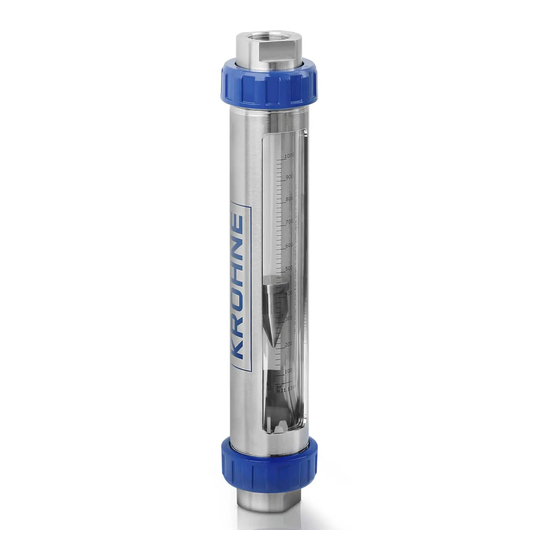
Advertisement

Quick Links

VA40 - VA45
VA40 - VA45
VA40 - VA45
VA40 - VA45
Variable area flowmeter
© KROHNE 08/2015 - 4000424402 - MA VA40-45 R04 en
Handbook
Handbook
Handbook
Handbook

Advertisement

Table of Contents
loading
Need help?

Need help?

Do you have a question about the VA40 and is the answer not in the manual?

Questions and answers

Subscribe to Our Youtube Channel

Summary of Contents for KROHNE VA40

  • Page 1 VA40 - VA45 VA40 - VA45 VA40 - VA45 VA40 - VA45 Handbook Handbook Handbook Handbook Variable area flowmeter © KROHNE 08/2015 - 4000424402 - MA VA40-45 R04 en...
  • Page 2 All rights reserved. It is prohibited to reproduce this documentation, or any part thereof, without the prior written authorisation of KROHNE Messtechnik GmbH. Subject to change without notice. Copyright 2015 by KROHNE Messtechnik GmbH - Ludwig-Krohne-Str. 5 - 47058 Duisburg (Germany) www.krohne.com 08/2015 - 4000424402 - MA VA40-45 R04 en...
  • Page 3: Table Of Contents

    4.6.1 Conversion of the function of ring type limit switch............. 20 4.6.2 Conversion of the function of limit switch MS14 ..............20 4.6.3 Conversion of the function of limit switch TG21..............21 5 Start-up 5.1 Standard device ......................22 08/2015 - 4000424402 - MA VA40-45 R04 en www.krohne.com...
  • Page 4 6.4.2 Form (for copying) to accompany a returned device............25 6.5 Disposal .......................... 25 7 Technical data 7.1 Functional principle......................26 7.2 Technical data......................... 27 7.3 Dimensions and weights ....................31 7.4 Measuring ranges......................33 www.krohne.com 08/2015 - 4000424402 - MA VA40-45 R04 en...
  • Page 5: Safety Instructions

    • Pressure Equipment Directive 97/23/EC • EMC Directive 2004/108/EC for instruments with electrical options • ATEX Directive 94/9/EC for instruments in Ex-areas The manufacturer certifies successful testing of the product by applying the CE mark. 08/2015 - 4000424402 - MA VA40-45 R04 en www.krohne.com...
  • Page 6: Safety Instructions From The Manufacturer

    (systems) will cause the warranty to be void. The respective "Standard Terms and Conditions" which form the basis for the sales contract shall also apply. www.krohne.com 08/2015 - 4000424402 - MA VA40-45 R04 en...
  • Page 7: Information Concerning The Documentation

    This document is provided to help you establish operating conditions, which will permit safe and efficient use of this device. Special considerations and precautions are also described in the document, which appear in the form of icons as shown below. 08/2015 - 4000424402 - MA VA40-45 R04 en www.krohne.com...
  • Page 8: Warnings And Symbols Used

    In general, devices from the manufacturer may only be installed, commissioned, operated and maintained by properly trained and authorized personnel. This document is provided to help you establish operating conditions, which will permit safe and efficient use of this device. www.krohne.com 08/2015 - 4000424402 - MA VA40-45 R04 en...
  • Page 9: Device Description

    Check for the correct supply voltage printed on the nameplate. Figure 2-1: Scope of delivery 1 Flowmeter in the version ordered 2 Manual 3 Certificates, calibration report (supplied to order only) 08/2015 - 4000424402 - MA VA40-45 R04 en www.krohne.com...
  • Page 10: Device Version

    • VA40S or VA45S - Tube socket • VA40F or VA45F - Flange version • VA40A - Aseptic version Optional versions: • VA40 with max. two limit switches, NAMUR • VA40 with potential-free Reed contact 2.2.1 Device version VA40 Figure 2-2: Device versions VA40...
  • Page 11: Nameplate

    • SO - sales order / item • Tag-No. - customer spec. • MD - year of manufacture • PA - KROHNE order • Vx - product configurator code • AC - article code 08/2015 - 4000424402 - MA VA40-45 R04 en www.krohne.com...
  • Page 12: Description Code

    V - Screw connection S - Tube socket F - Flange connection 2 Material of the connection R - Stainless steel 1.4404 (316 L) ST - Steel, electroplated and chromized PV - Platics PVDF www.krohne.com 08/2015 - 4000424402 - MA VA40-45 R04 en...
  • Page 13: Installation

    • Store the flowmeter in a dry and dust-free location. • Avoid lasting direct exposure to the sun. • Store the flowmeter in its original packaging. • The permissible storage temperature is from -40...+80°C / -40...176°F for standard meters. 08/2015 - 4000424402 - MA VA40-45 R04 en www.krohne.com...
  • Page 14: Installation Condtitions

    When assembling the meter, tighten the union nuts with strap wrench. Make sure the O- ring is positioned correctly! • A A A A - Aseptic the same as tube socket www.krohne.com 08/2015 - 4000424402 - MA VA40-45 R04 en...
  • Page 15: Electrical Connections

    Check for the correct supply voltage printed on the nameplate. 4.2 VA40 limit switches The flowmeter VA40 can be equipped with a maximum of two limit switches: Type bistable (stable changeover from NC to NO contact and vice versa) Type monostable (switching pulse at operating point)
  • Page 16: Connection Ring Type Limit Switch

    - black switch contact bu - blue supply voltage - 4.2.2 Connection limit switch type MS14 Figure 4-3: Connection limit switch type MS14 1 Connection Reed-switch 2 Connection Receiver device 3 Terminal connection (potential-free) www.krohne.com 08/2015 - 4000424402 - MA VA40-45 R04 en...
  • Page 17: Connection Limit Switch Type Tg21

    • Only slightly tighten screw 1! (Risk of breaking the glass) The operating point is, as shown, at approx. half height of the ring 2. The exact operating point is also dependent on the size of the used float! 08/2015 - 4000424402 - MA VA40-45 R04 en www.krohne.com...
  • Page 18: Limit Switch Settings Ms14

    • Untighten bracket screw 1 and set switching position • Secure bracket screw 1 The distance between the limit switch and the casing is factory set at approx. 1 mm (0.039") with the clamping screw 2. www.krohne.com 08/2015 - 4000424402 - MA VA40-45 R04 en...
  • Page 19: Minimum Clearance Between Two Ring Initiators

    Precondition: The float is located outside the limit switch. Limit switch 3-wire transistor bistable ndependent of float position like transit 2: output Ua ≤1 VDC Precondition: The float is located outside the limit switch. 08/2015 - 4000424402 - MA VA40-45 R04 en www.krohne.com...
  • Page 20: Limit Switch Function Reversal

    Two contact functions are available: • Closing, at increasing flow. Arrow on reed cartridge points towards measuring glass. • Closing, at decreasing flow. Arrow on reed cartridge points away from measuring glass. www.krohne.com 08/2015 - 4000424402 - MA VA40-45 R04 en...
  • Page 21: Conversion Of The Function Of Limit Switch Tg21

    4 on the dipping vane The switching reproducibility is < 3% of the full-scale range and is influenced by the force of the frictional connection! 08/2015 - 4000424402 - MA VA40-45 R04 en www.krohne.com...
  • Page 22: Start-Up

    When measuring liquids, vent the pipes carefully. • When measuring gases, increase pressure slowly. • Avoid float impact (e.g. caused by solenoid valves), as this is likely to damage the measuring • unit or float. www.krohne.com 08/2015 - 4000424402 - MA VA40-45 R04 en...
  • Page 23: Service

    We advise that inspections be carried out at least once per year. For VA40 (aseptic) a strap wrench is recommended to open the flowmeter. Devices with flange connection tighten the union nut first before installation.
  • Page 24: Spare Parts Availability

    • such dangerous substances, to enclose a certificate with the device confirming that is safe to handle and stating the • product used. www.krohne.com 08/2015 - 4000424402 - MA VA40-45 R04 en...
  • Page 25: Form (For Copying) To Accompany A Returned Device

    The user must dispose of the WEEE to a designated collection point for the recycling of WEEE or send them back to our local organisation or authorised representative. 08/2015 - 4000424402 - MA VA40-45 R04 en www.krohne.com...
  • Page 26: Technical Data

    7.1 Functional principle The flowmeter operates with the principle of variable area flowmeters. A glass cone is installed in the measuring unit of VA40/45, in which a suitably formed float can move freely up and down. The flowmeter is inserted into a vertical pipeline and the medium flows through it from bottom to top.
  • Page 27: Technical Data

    VA40 - DN50 7 bar / 102 psig VA45 1 bar / 14.5 psig Installation conditions ≥ 5 x DN Inlet run ≥ 3 x DN Outlet run 1 other pressures upon request 08/2015 - 4000424402 - MA VA40-45 R04 en www.krohne.com...
  • Page 28 For devices to be used in hazardous areas, special temperature ranges apply. These can be found in the separate instructions. Max. measuring temperature T (standard) -20...+100°C -4...+212°F Max. ambient temperature T -20...+100°C -4...+212°F amb. 1 higher temperatures on request www.krohne.com 08/2015 - 4000424402 - MA VA40-45 R04 en...
  • Page 29 MS14/A TG21 G 17.12 ring ø15mm N 51.21 MS14/A TG21 N 18.07 MS14/A N 18.09 MS14/A N 18.13 MS14/A N 19.09 MS14/A N 19.13 MS14/A N 19.19 MS14/A N 19.26 MS14/A 08/2015 - 4000424402 - MA VA40-45 R04 en www.krohne.com...
  • Page 30 Technical data TG21 Rated voltage 8VDC Current consumption, inactive Current consumption, active Ambient temperature -25°C...+100°C / -13...+212°F Type of protection according to EN 60529 / IP 67 (NEMA 6) IEC 529 www.krohne.com 08/2015 - 4000424402 - MA VA40-45 R04 en...
  • Page 31: Dimensions And Weights

    17,7 16,7 14,8 DN40 1 1/2" 9,26 1,81 14,8 17,7 16,7 14,8 DN50 2" 8,94 2,44 14,8 17,7 16,7 14,8 1 option 500 mm 2 Option 19,7" VA40/V VA40/S VA40/F VA40/A 08/2015 - 4000424402 - MA VA40-45 R04 en www.krohne.com...
  • Page 32 " DN25 1" G¾"...G1" 1" NPT DN25 1" SC25 DN40 1 1/2" G1½" 1 ½" NPT DN40 1 ½" SC40 DN50 2" G2" 2" NPT DN50 2" SC50 1 only VA40 www.krohne.com 08/2015 - 4000424402 - MA VA40-45 R04 en...
  • Page 33: Measuring Ranges

    The specified pressure drops are valid for water and air at maximum flow rate. Other flow ranges on request. Conversion of other media or operating data (pressure, temperature, density, viscosity) is performed using the calculation method in accordance with VDI /VDE Directive 3513 08/2015 - 4000424402 - MA VA40-45 R04 en www.krohne.com...
  • Page 34 Other flow ranges on request. Conversion of other media or operating data (pressure, temperature, density, viscosity) is performed using the calculation method in accordance with VDI /VDE Directive 3513 www.krohne.com 08/2015 - 4000424402 - MA VA40-45 R04 en...
  • Page 35 The flow measurement of gases are refered to Nl/h or Nm /h: Volume flow in Normal state 0°C, 1.013 bar abs. (DIN 1343) SCFM or SCFH: Volume flow in Standard state 15°C, 1.013 bar abs. (ISO 13443) 08/2015 - 4000424402 - MA VA40-45 R04 en www.krohne.com...
  • Page 36 • Process Analysis • Services Head Office KROHNE Messtechnik GmbH Ludwig-Krohne-Str. 5 47058 Duisburg (Germany) Tel.: +49 203 301 0 Fax: +49 203 301 10389 info@krohne.com The current list of all KROHNE contacts and addresses can be found at: www.krohne.com...

This manual is also suitable for:

Va45

Table of Contents

Save PDF