Table of Contents
Advertisement
Quick Links
Advertisement
Table of Contents

Related Manuals for Ecler TRAILSB6T


Summary of Contents for Ecler TRAILSB6T
- Page 1 TRAILSB6T LOUDSPEAKERS Concealable Subwoofer USER MANUAL...
-
Page 2: Table Of Contents
INDEX IMPORTANT REMARK ..................3 IMPORTANT SAFETY INSTRUCTIONS .............. 4 IMPORTANT NOTE ..................6 INTRODUCTION ..................... 6 MAIN SPECIFICATIONS ................... 6 CONNECTION ....................7 LOCATION AND INSTALLATION ..............8 6.1 Procedure for installation in a suspended ceiling ........... 9 6.2 Flat surface installation procedure ............... 10 6.3 Procedure for installation behind a partition wall ........ -
Page 3: Important Remark
1. IMPORTANT REMARK The lightning flash with arrowhead symbol, within an equilateral triangle, is intended to alert the user to the presence of uninsulated “dangerous voltage” within the product’s enclosure that may be of sufficient magnitude to constitute a risk of electric shock to persons. The exclamation point within an equilateral triangle is intended to alert the user to the presence of important operating and maintenance (servicing) instructions in the literature accompanying the appliance. -
Page 4: Important Safety Instructions
2. IMPORTANT SAFETY INSTRUCTIONS Read these instructions. 2. Keep these instructions. 3. Heed all warnings. 4. Follow all instructions. 5. Do not use this apparatus near water. 6. Clean only with dry cloth. 7. Do not block any ventilation openings. Install in accordance with the manufacturer’s instructions. - Page 5 NOTE: This equipment has been tested and found to comply with the limits for a Class A digital device, pursuant to part 15 of the FCC Rules. These limits are designed to provide reasonable protection against harmful interference when the equipment is operated in a commercial environment.
-
Page 6: Important Note
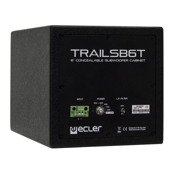
Services. 4. INTRODUCTION TRAILSB6T is intended as a bass reinforcement and is constructed of wood, with a very compact design. It incorporates a 6.5-inch, 60 Wrms, 8 Ω driver, a transformer with four selectable powers for use in 70/100 V lines and an internal low-pass filter. -
Page 7: Connection
6. CONNECTION The TRAILSB6T operates into high or low impedance. For this reason, it has a rear panel fitted with a 5-position switch for operating-mode selection. The first four positions enable the system to operate into high impedance mode, and the fifth is for low impedance. -
Page 8: Location And Installation
Note: the TRAILSB6T loudspeaker may be adapted in several ways to your needs by means of the supplied installation accessories. The procedures described in this manual are examples, but there are other installation options that can be executed by following the instructions in this manual;... -
Page 9: Procedure For Installation In A Suspended Ceiling
68 mm hole must be made in the ceiling for its installation and that of the trim grille. 1. Screw the metal fittings to the TRAILSB6T using the supplied screws. This can be executed by using several of the holes in the supports for the coupling bar installation in the desired position. -
Page 10: Flat Surface Installation Procedure
1. Screw the lower metal fitting to the wall at the required height. Remember that the lower part of the TRAILSB6T will rest on this angle. See figure 2. 2. Check that the system is stable and then carry out the necessary connections and adjustments before installing the upper support. -
Page 11: Procedure For Installation Behind A Partition Wall
3. Screw the lower metal fitting to the wall at the required height. Remember that the lower part of the TRAILSB6T will rest on this angle and that the coupling pipe has to pass through the hole. See Figure 3. -
Page 12: Technical Specifications
Dimensions (W x D x H) 200 x 200 x 320 mm / 7.9 x 7.9 x 12.6 inches Weight 6.5 kg / 14.3 lb 9. CONTENTS OF PACKAGING TRAILSB6T Installation accessories: 4 metal fittings and 16 screws for securing on the loudspeaker ... - Page 13 NEEC AUDIO BARCELONA S.L. reserves the right to make changes or improvements in the design or manufacturing that may affect these product specifications. Motors, 166‐168 08038 Barcelona ‐ Spain ‐ (+34) 932238403 information@ecler.es www.ecler.com...
Need help?
Do you have a question about the TRAILSB6T and is the answer not in the manual?
Questions and answers