Advertisement
Quick Links
Installation Instructions for Auditcon
Dial Assembly
Dial
Assembly
Mounting
Cable
Screws (2)
Shields (2)
Figure 1 - Dead Bolt Lock Parts
The installation instructions are the basis for Security Agency Approvals.
The lock installation must be done in accordance to these instructions
in order to maintain the labeled approval level.
Design Parameters for Auditcon 2 Series Locks
1. Bolt dimensions (nominal): .312 inches x 1.000 inches/8 x 25.4mm
2. Bolt movement (nominal) : .465 inches/11.8mm
3. Bolt extension: .465 inches/11.8 mm
4. Maximum load movable by the bolt: 5 lbs. (22N)
Note: Auditcon 2 dead bolt locks may not open if more than 5 lbs.
(22N) of force is applied to the end or side of the bolt.
5. Maximum load against bolt when thrown
6. The lock can be fitted to safes or vault doors of any material.
Note: As is the case with all mechanical and electronic locking devices,
the container and boltworks must be designed to protect the lock.
®
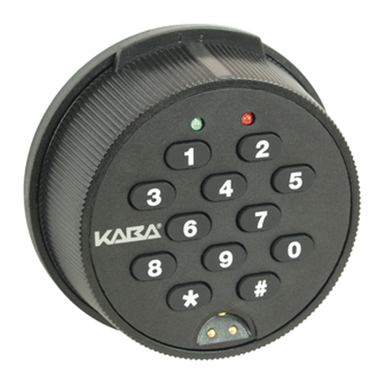
2 Series Locks - Models 52R, 252R, 552R - Round Housing Dead Bolt
Lock Case
Assembly
Keypad
Assembly
Lock Case
with Decal
Mounting
Screws (4)
Spindle
Mounting
Screw
Spindle &
Tube
Cable
Not Shown in Photo: Insulator Tape
Prepare for New Installation of the Lock (If Required)
1. Use the template provided to establish the exact locations
(relative to the spindle hole) of the mounting holes for the lock
assembly.
2. The spindle hole diameter can be a minimum of .406" (10.3mm) to
a maximum of .438" (11.1mm). The .406" (10.3mm) diameter is
recommended. Spindle hole must be deburred.
3. The dial assembly mounting screws require drilled and tapped
holes to 3/8" (9.5mm) depth if possible (minimum 1/4" or 6.4mm
depth required.) Drill either the two horizontal mounting holes or the
two vertical holes.
(all directions): 224.8 lbs. (1kN)
4. When mounting the lock unit (i.e., integrating it in a boltwork),
make sure that the lock bolt has clearance to freely move to its end
positions and that the shifting force works only in the axial direction
(direction of movement). Lateral forces should not be exerted on the
lock.
5. If other parts of the boltwork are to be connected to the lock unit
(e.g., for activating a blocking device), corresponding adapters can
be fixed with screws (#10-32 or M4) to the front of the lock bolt
(tightening torque for 15mm screwing depth: 200Ncm maximum).
Basic Tools and Materials Needed
•
Medium Phillips head screwdriver (#2)
(recommend magnetized tip)
•
9/64" Allen Wrench
•
Fine pitch hacksaw (32 teeth/inch)
•
Small flat file
•
All-purpose scissors
•
Tape measure or ruler
•
ESD wrist band
Recommended, but not required:
•
Torque screwdriver (30 inch-pounds/3.4
newton-meters capacity)
•
Small vise grip
•
Loctite
262 (Red) for use on lock case
®
mounting screws
WARNING: Kaba Mas locks are protected
from 25,000 V Electrostatic Discharge
(ESD) damage when correctly installed.
Follow these precautions to avoid ESD
damage when installing the lock:
• Handle the keypad assembly by the
outer edge only.
• Use an ESD wrist band grounded to the
lock or container during installation.
Part I: Install Lock Case Assembly
WARNING:
Do not take the lock case assembly apart. There are
no field servicable parts inside lock case.
1. Insert a cable shield into the deburred spindle hole from the back
side of the container door.
2. Place the protective tube over the
tube retainer on the lock case. (Figure 2)
3. While holding the lock case assembly,
guide the tube through the spindle hole
and place the lock case flush against the
inside of the container door.
4. Mark the tube flush to the outside of
the container door (to within 1/16" or
1.6mm).
5. Remove lock case assembly from door
and cut the tube just inside your mark.
6. Plug one end of the ribbon cable into
the connector on the bottom of the lock
case. (Figure 3)
7. Lay the ribbon cable in the cable
routing path on the lock case and tape
the cable to the outside of the tube with
the insulator tape provided. (Figure 3)
8. Hold the lock case assembly and carefully guide the loose end of
the ribbon cable and the tube through the spindle hole so that they are
accessible outside of the container door.
9. Mount the lock case assembly to the inside of the container door
using the four 1/4-20 (or M6-1) lock case mounting screws. (Torque 25-
30 lbs., 2.8-3.4 N-M)
Note:
It is recommended that you use Loctite
case mounting screws.
10. Insert the end of the spindle with the screw hole into the lock case
assembly until the spindle is properly seated. The grooved side of the
spindle should be oriented so that the grooves in the spindle align with
the grooves in the drive cam. Turn the spindle to extend the bolt and
ensure that the grooves are facing toward the bolt.
11. Mark the spindle shaft 3/8" (9.5mm)
from the outside of the container door
(plus or minus 1/16" or 1.6mm allowed).
(Figure 4)
12. Remove the spindle from the lock
case to prevent damage to the cable
while cutting.
13. Cut the spindle on the mark and
deburr.
14. Re-insert the spindle. Refer to Step 10 for proper positioning.
Document # 3047.025 Rev. B - 12/06
Figure 2
Figure 3
262 (Red) on the lock
®
Figure 4
Advertisement

Subscribe to Our Youtube Channel
Related Manuals for Kaba Mas Auditcon 52R


Summary of Contents for Kaba Mas Auditcon 52R
- Page 1 5. Remove lock case assembly from door Dial and cut the tube just inside your mark. Figure 3 WARNING: Kaba Mas locks are protected Assembly from 25,000 V Electrostatic Discharge Mounting 6. Plug one end of the ribbon cable into...
- Page 2 4-pin connector on the back © 2005-2006 Kaba Mas Corporation. All rights reserved. Note: After correctly entering a valid combination, you must of the keypad assembly.
- Page 3 SUFFICIENT TO CLEAR A 1 INCH BOLT • Loctite 262 (Red) for use on lock ® case mounting screws WARNING: Kaba Mas locks are Lock Case Figure 4 protected from 25,000 V Mounting Screws (3) Electrostatic Discharge (ESD) damage when correctly installed.
- Page 4 WARNING: Do not take the lock case assembly apart. The lock will not operate if the back cover has been removed. © 2005-2006 Kaba Mas Corporation. All rights reserved. Product warranty information can be found at: www.kaba-mas.com Kaba Mas Corporation 749 W.
Need help?
Do you have a question about the Auditcon 52R and is the answer not in the manual?
Questions and answers