Moxa Technologies IA260 User Manual
Hide thumbs
Also See for IA260:
- User manual (71 pages) ,
- Hardware user manual (23 pages) ,
- Specifications (3 pages)

Related Manuals for Moxa Technologies IA260


Summary of Contents for Moxa Technologies IA260
- Page 1 IA260 Hardware User’s Manual Edition 4.0, March 2017 www.moxa.com/product © 2017 Moxa Inc. All rights reserved.
- Page 2 IA260 Hardware User’s Manual The software described in this manual is furnished under a license agreement and may be used only in accordance with the terms of that agreement. Copyright Notice © 2017 Moxa Inc. All rights reserved. Trademarks The MOXA logo is a registered trademark of Moxa Inc.
-
Page 3: Table Of Contents
Table of Contents Introduction ............................1-1 Overview ............................1-2 Model Descriptions and Package Checklist ....................1-2 Product Features ..........................1-3 Product Hardware Specifications ......................1-3 Hardware Block Diagram ........................1-6 Hardware Introduction ........................2-1 Appearance ............................2-2 Top View ............................ 2-2 Front View .......................... -
Page 4: Introduction
VGA output, a CompactFlash socket for adding additional storage space, and USB ports for a keyboard/mouse connection or for adding additional storage space. These features make the IA260 series ideal for your industrial embedded applications, such as SCADA, manufacturing automation, and other industrial applications. -
Page 5: Overview
Because of its VGA output capability, the IA260 can be used for protocol conversion or data acquisition for field site devices, and is also suitable for SCADA systems in industrial applications, such as manufacturing automation, production line process monitoring, and mining automation. -
Page 6: Product Features
IA260 Hardware Introduction Both models are shipped with the following items: • 1 IA260 Embedded Computer • Wall-Mounting Kit • DIN-Rail Mounting Kit (attach to the product’s casing) • Ethernet Cable: RJ45 to RJ45 cross-over cable, 100 cm • CBL-4PINDB9F-100: 4-pin header to DB9 female console port cable, 100 cm •... - Page 7 IA260 Hardware Introduction Serial Communication Parameters Data Bits: 5, 6, 7, 8 Stop Bits: 1, 1.5, 2 Parity: None, Even, Odd, Space, Mark Flow Control: RTS/CTS, XON/XOFF, ADDC® (automatic data direction control) for RS-485 Baudrate: 50 bps to 921.6 kbps (supports nonstandard baudrates; see user's manual for details)
- Page 8 IA260 Hardware Introduction Input Current: With no load on USB ports: • 240 mA @ 24 VDC • 480 mA @ 12 VDC With full load on USB ports: • 450 mA @ 24 VDC • 900 mA @ 12 VDC Power Consumption: With no load on USB ports: 5.8 W...
-
Page 9: Hardware Block Diagram
IA260 Hardware Introduction Hardware Block Diagram... -
Page 10: Hardware Introduction
LED indicators allow users to monitor performance and identify trouble spots quickly, and the multiple ports can be used to connect a variety of devices. The IA260 comes with a reliable and stable hardware platform that lets you devote the bulk of your time to application development. In this chapter, we provide basic information about the embedded computer’s hardware and its various components. -
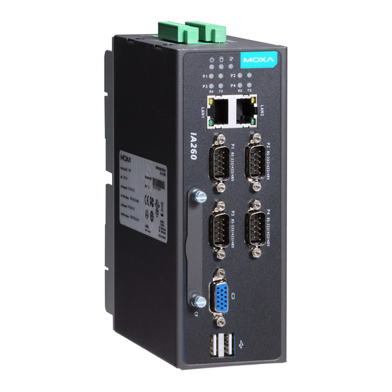
Page 11: Appearance
IA260 Hardware Hardware Introduction Appearance Top View Front View... -
Page 12: Rear View
IA260 Hardware Hardware Introduction Rear View Dimensions... -
Page 13: Led Indicators
Reset Button The IA260 has a reset button located on the top panel. The reset button can be used to do a simple Reset, which is equivalent to turning the power off and then back on again, or Reset to default, which returns the IA260 to its factory default parameter configuration. -
Page 14: Real Time Clock
DIN-Rail Mounting The aluminum DIN-Rail attachment plate is already attached to the product’s casing. To attach the plate to IA260, make sure that the stiff metal spring is facing the top of the IA260, as shown in the following figures. STEP1:... -
Page 15: Wall Mounting (Optional)
IA260 Hardware Hardware Introduction Wall Mounting (optional) For some applications, you will find it convenient to mount the IA260 on the wall, as depicted in the following illustrations. STEP 1: Attach the wallmount kit to the IA260’s rear panel with 2 screws. -
Page 16: Hardware Connection Description
Hardware Connection Description This section describes how to connect the IA260 to a network and various devices for first time testing purposes. The following topics are covered in this chapter: Wiring Requirements Connecting the Power Grounding the Unit ... -
Page 17: Wiring Requirements
Connecting the Power The IA260 has a 3-pin terminal block for a 12 to 48 VDC power input. The following figures show how the power input interface connects to external power sources. If the power is properly supplied, the Power LED will light up. -
Page 18: Grounding The Unit
Connecting to the Console Port The IA260’s console port is a 4-pin pin-header RS-232 port. It is designed for serial console terminals, which are useful for identifying the boot up message, or for debugging when the system cannot boot up. -
Page 19: Connecting To A Display
– Connecting to a Keyboard and Mouse Use the 2 USB hosts located on the front side of unit to connect a keyboard and mouse to the IA260. Connecting to the Network Connect one end of the Ethernet cable to one of the IA260’s 10/100M Ethernet ports (8-pin RJ45) and the other end of the cable to the Ethernet network. -
Page 20: Connecting To A Serial Device
Connecting to a Serial Device Use properly wired serial cables to connect the IA260 to serial devices. The serial ports of the IA260 use male DB9 connectors. The ports can be configured by software for RS-232, RS-422, or 2-wire RS-485. The precise... -
Page 21: Digital Input Wiring
Digital Output Wiring Insert CompactFlash Card The IA260 has a built-in CompactFlash socket that allows users to add additional memory by inserting a CompactFlash memory card, without any risk to the computer. Follow the instructions below to insert a CompactFlash card: 1. -
Page 22: Usb Hosts
5. Screw the protective cover to the font panel. ATTENTION The IA260 does not support CompactFlash hot swap and PnP (Plug and Play) function. It is necessary to remove power source first before inserting or removing the CompactFlash card. USB Hosts The IA260 provides 2 USB 2.0 full speed hosts (OHCI), type A connectors, which support a keyboard or mouse,... -
Page 23: Regulatory Approval Statements
Regulatory Approval Statements This device complies with part 15 of the FCC Rules. Operation is subject to the following two conditions: (1) This device may not cause harmful interference, and (2) this device must accept any interference received, including interference that may cause undesired operation.
Need help?
Do you have a question about the IA260 and is the answer not in the manual?
Questions and answers