Advertisement
Quick Links
IA3341
Quick Installation Guide
First Edition, May 2010
1. Overview
The IA3341 is based on the MOXA ART ARM9 industrial processor, and
features two RS-232/422/485 serial ports, dual LANs, four digital input
channels, and four digital output channels. In addition, the IA3341
computer has two analog input channels and two thermocouple channels
to make it the ideal solution for a variety of industrial applications, such
as solar power and environmental monitoring.
2. Package Checklist
Before installing the IA3341, verify that the package contains the
following items:
IA3341-LX embedded computer
Wall mounting kit
Ethernet cable: RJ45 to RJ45 cross-over cable, 100 cm
CBL-4PINDB9F-100: 4-pin pin header to DB9 female console port
cable, 100 cm
Terminal block to power jack converter
Document and Software CD or DVD
Quick Installation Guide (printed)
Product Warranty Statement (printed)
NOTE: Please notify your sales representative if any of the above items
are missing or damaged.
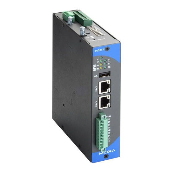
3. IA3341 Panel Layout
The following figures show the panel layouts of the IA3341.
— 1 —
Front View
System LED x 3
(Power, Ready, Storage)
Serial LED x 4
(Tx, Rx)
USB 2.0 Host x1
(type A)
10/100 Mbps
LAN Port x2
(RJ45)
DI x 4
DO x 4
Top and Bottom Views
Power Input
SD Socket
Reset to Default
Button
LED Indicators
The IA3341 has 11 LED indicators on the front panel. Refer to the
following table for information about each LED.
LED
Color
Name
Green
Power
Off
Green
Ready
Off
Green
Storage
Off
LAN1,
Orange
LAN2
Green
P1-P2
Green
P/N: 1802033410010
Console Port
AI x 2
Thermocouple
Input x 2
Serial Port x2
(RS-232/422/485, DB9)
Meaning
Power is ON.
No power is being received, or power error exists.
OS is ready and functioning normally (after booting up).
OS is not ready.
Data is being written to or read from the storage unit.
Storage unit is idle.
10 Mbps Ethernet connection
100 Mbps Ethernet connection
Serial port is transmitting TX data to the serial device.
— 2 —
(TX)
Off
Serial port is not transmitting TX data to the serial device.
P1-P2
Orange
Serial port is receiving RX data from the serial device.
(RX)
Off
Serial port is not receiving RX data from the serial device.
4. Installing the IA3341
Placement Options
DIN-Rail Mounting
The aluminum DIN-Rail attachment plate is already attached to the
product's casing. To attach the IA3341 to the DIN-Rail, make sure the
stiff metal spring is facing the top of the IA3341, as shown in the
following figures.
STEP 1: Insert the top of the
STEP 2: The DIN-Rail attachment
DIN-Rail into the slot just below
unit will snap into place as shown.
the stiff metal spring.
metal
spring
DIN-Rail
DIN-Rail
To remove the IA3341 from the DIN-Rail, simply reverse Steps 1 and 2.
Wall or Cabinet Mounting
The IA3341 comes with two metal plates for attachment to a wall or the
inside of a cabinet.
STEP 1: Remove the aluminum
STEP 2: Mounting the IA3341
DIN-Rail attachment plate from
on the wall requires four screws.
the IA3341's rear panel, and
Attach the screws on the two
then attach the wall mount
plates, as shown below.
plates, as shown in the figure
below.
— 3—
metal
spring
Screws
Screws
Advertisement

Related Manuals for Moxa Technologies IA3341


Summary of Contents for Moxa Technologies IA3341
- Page 1 To attach the IA3341 to the DIN-Rail, make sure the The IA3341 is based on the MOXA ART ARM9 industrial processor, and stiff metal spring is facing the top of the IA3341, as shown in the features two RS-232/422/485 serial ports, dual LANs, four digital input...
- Page 2 To power on the IA3341, connect the power source to the terminal block Connect the 12 to 48 VDC LPS or Class 2 power line to the IA3341’s located on the top panel. Note that the Shielded Ground wire should be terminal block.
Need help?
Do you have a question about the IA3341 and is the answer not in the manual?
Questions and answers