
Subscribe to Our Youtube Channel
Related Manuals for Moxa Technologies DRP-C100 Series


Summary of Contents for Moxa Technologies DRP-C100 Series
- Page 1 DRP-C100 Series Hardware User Manual Version 1.0, October 2023 www.moxa.com/products © 2023 Moxa Inc. All rights reserved.
- Page 2 DRP-C100 Series Hardware User Manual The software described in this manual is furnished under a license agreement and may be used only in accordance with the terms of that agreement. Copyright Notice © 2023 Moxa Inc. All rights reserved. Trademarks The MOXA logo is a registered trademark of Moxa Inc.
-
Page 3: Table Of Contents
Table of Contents Introduction ............................5 Package Checklist ..........................5 Product Features ........................... 5 Hardware Specifications ......................... 5 Hardware Introduction ......................... 6 Appearance ............................6 Dimensions ............................10 LED Indicators ............................. 13 Reset Button ............................14 Real Time Clock (RTC) .......................... 14 Hardware Connection Description ...................... - Page 4 Enabling UEFI Secure Boot ......................46 Enroll EFI Image .......................... 46 Enroll Customer Key ........................48 Upgrading the BIOS ..........................49 Regulatory Approval Statement ......................53...
-
Page 5: Introduction
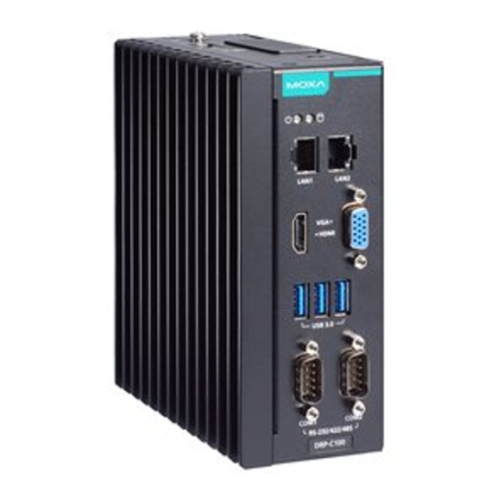
1. Introduction The DRP-C100 Series DIN-rail mountable computers are powered by Intel® Celeron® or Intel® Core™ i5/i7 processor. The computers come with a rich set of interface options including up to 8 software-selectable RS- 232/422/485 serial ports and up to 10 gigabit Ethernet ports. The communication interfaces are located on the front and rear sides of the product, enabling easy access and expansion for industrial applications. -
Page 6: Hardware Introduction
2. Hardware Introduction In this chapter, we provide information about the DRP-C100 computer’s hardware components. Appearance DRP-C100-C1-T/DRP-C100-C5-T/DRP-C100-C7-T Models Front View Top View Bottom View DRP-C100 Series Hardware User Manual... - Page 7 DRP-C100-C1-8L-T/DRP-C100-C5-8L-T/DRP-C100-C7-8L-T Models Front View Top View Bottom View DRP-C100 Series Hardware User Manual...
- Page 8 DRP-C100-C1-6C-T/DRP-C100-C5-6C-T/DRP-C100-C7-6C-T Models Front View Top View Bottom View DRP-C100 Series Hardware User Manual...
- Page 9 DRP-C100-C1-2L4C-T/DRP-C100-C5-2L4C-T/DRP-C100-C7-2L4C-T Models Front View Top View Bottom View DRP-C100 Series Hardware User Manual...
-
Page 10: Dimensions
Dimensions DRP-C100-C1-T/DRP-C100-C5-T/DRP-C100-C7-T Models DRP-C100 Series Hardware User Manual... - Page 11 DRP-C100-C1-8L-T/DRP-C100-C5-8L-T/DRP-C100-C7-8L-T Models DRP-C100 Series Hardware User Manual...
- Page 12 DRP-C100-C1-6C-T/DRP-C100-C5-6C-T/DRP-C100-C7-6C-T Models DRP-C100 Series Hardware User Manual...
-
Page 13: Led Indicators
Steady ON: 1000 Mbps Ethernet link Yellow (1000 Mbps) Blinking: Data is being transmitted or received No Ethernet connection Yellow Blinking: Data is being accessed from the CFast card Storage (CFast) Data is not being accessed from the CFast card DRP-C100 Series Hardware User Manual... -
Page 14: Reset Button
Contact a qualified Moxa support engineer if you have any questions about the RTC battery. ATTENTION There is a risk of explosion if the battery is replaced by a battery of the incorrect type. DRP-C100 Series Hardware User Manual... -
Page 15: Hardware Connection Description
Insert the top of the DIN rail into the slot just below the upper hook of the DIN-rail mounting kit. STEP 3: Press the computer towards the DIN rail until the mounting kit snaps into place. DRP-C100 Series Hardware User Manual... -
Page 16: Connecting The Power
The power LED will light up to indicate that power is being supplied to the computer. It should take about 30 to 60 seconds for the operating system to complete the boot-up process. Definition DRP-C100 Series Hardware User Manual... -
Page 17: Wiring Requirements
NOTE Do not run signal and communication wiring together with power wiring in the same wire conduit. To avoid interference, wires with different signal characteristics should be routed separately. DRP-C100 Series Hardware User Manual... -
Page 18: Connecting To A Network
For reliable Ethernet connections, we recommend enabling the ports in standard temperatures and keeping them enabled in high/low temperature environment. 10/100 Mbps 1000 Mbps ETx+ TRD(0)+ ETx- TRD(0)- ERx+ TRD(1)+ – TRD(2)+ – TRD(2)- ERx- TRD(1)- – TRD(3)+ – TRD(3)- DRP-C100 Series Hardware User Manual... -
Page 19: Connecting To A Serial Device
Inserting a SD/CFast Card The DRP-C100 comes with two slots that allow users to insert one SD card and one CFast card. To install the cards, do the following: Unfasten the two screws on the slot cover. DRP-C100 Series Hardware User Manual... -
Page 20: Replacing The Rtc Battery
Unfasten the two screws on the battery cover. Take off the cover. The battery is attached to the slot cover as indicated in the image. Unplug the connector of the battery-cover assembly from the internal wire of the slot. DRP-C100 Series Hardware User Manual... - Page 21 Moxa’s technical support staff for assistance, if necessary. • To reduce the risk of fire or burns, do not disassemble, crush, or puncture the battery; do not dispose of in fire or water and do not short external contacts. DRP-C100 Series Hardware User Manual...
-
Page 22: Bios Setup
Setup Utility: Enter the BIOS configuration menu • Intel® Management Engine BIOS Extension: Enter the AMT configuration menu (not supported in • models with Intel® Celeron® and Core™ i3 processors) Select F2 to enter the BIOS configuration. DRP-C100 Series Hardware User Manual... - Page 23 Select or go to Submenu. EN TER The BIOS configuration screen will be shown when you enter the Setup Utility option. NOTE The Processor Type information may vary depending on the model that you have purchased. DRP-C100 Series Hardware User Manual...
-
Page 24: Main Page
Main Page The Main page displays basic hardware information, such as model name, BIOS version, and CPU type. Advanced Settings Select the Advanced tab in the main menu to open the advanced features screen. DRP-C100 Series Hardware User Manual... -
Page 25: Boot Configuration
Boot Configuration The Numlock option allows configuration of the Numlock value. Options: On (default), Off. DRP-C100 Series Hardware User Manual... -
Page 26: Sata Configuration
SATA Port Hot Plug This setting allows you to enable/disable hot-plugging capabilities (the ability to remove the drive while the computer is running) that are configured by software for installed storage drives. Options: Disabled (default), Enabled DRP-C100 Series Hardware User Manual... -
Page 27: Cpu Configuration
It also increases processor throughput, improving overall performance on threaded software. Options: Disabled, Enabled (default) Turbo Mode Enable/Disable processor Turbo Mode (not supported in models with an Intel® Celeron® ). Options: Disabled, Enabled (default) DRP-C100 Series Hardware User Manual... -
Page 28: Video Configuration
2D/3D graphics performance. DVMT Total Gfx Mem. This item allows you to configure the maximum amount of memory DVMT will use when allocating additional memory for the internal graphics device. Options: 256 MB (default), 128 MB, Max. DRP-C100 Series Hardware User Manual... -
Page 29: Chipset Configuration
This item allows you to enable/disable the computer from automatically powering up after system power is re-enabled. Options: ON (default), OFF, Last State Load Default After Cleaning RTC Battery System will load the default if a RTC battery loss is detected. Options: Disabled, Enabled (default) DRP-C100 Series Hardware User Manual... -
Page 30: Pch-Fw Configuration
When Disabled ME will be put into ME Temporarily Disabled Mode. Options: Disabled, Enabled (default) ME Unconfig on RTC Clear When Disabled ME will not be unconfigured on RTC Clear. Options: Disabled, Enabled (default) Unconfigure ME Unconfigure ME with resetting MEBx password to default. DRP-C100 Series Hardware User Manual... -
Page 31: Console Redirection
This section allows you to configure the console redirection settings. Console Serial Redirect When the Console Redirection Function is enabled, the console information will be sent to the display monitor and the serial port (COM1). Options: Disabled (default), Enabled DRP-C100 Series Hardware User Manual... -
Page 32: Sio Ite8786E
SIO ITE8786E This section allows users to configure SIO settings. DRP-C100 Series Hardware User Manual... -
Page 33: Hardware Monitor
Enable: Enable the UART Port 2 connection (default) NOTE All other UART ports can only be configured by the OS utility. Hardware Monitor This section allows you to view stats such as CPU and system temperature, voltage levels, and other chipset information. DRP-C100 Series Hardware User Manual... -
Page 34: Security Settings
This item shows if the system has TMP device and its type. TPM State This item allows you view the status of current TPM settings. Clear TPM This item allows users to remove all TPM context associated with a specific owner. DRP-C100 Series Hardware User Manual... -
Page 35: Set Supervisor Password
This item allows you to set the supervisor password. Select the Set Supervisor Password option and enter the password and confirm the password again. To delete the password, select the Set Supervisor Password option and enter the old password; leave the new password fields blank, and then press enter. DRP-C100 Series Hardware User Manual... - Page 36 Enable: System will ask for the password on post time Disable: System will ask for the password to go to the setup utility Config-Only: System will only ask for the password when you select the config (F2) option DRP-C100 Series Hardware User Manual...
-
Page 37: Power Settings
Options: Disabled (default); By Every Day (user specifies a regular daily time when the computer will power up); By Day of Month (user specifies a regular day each month when the computer will power up) DRP-C100 Series Hardware User Manual... -
Page 38: Boot Settings
This item allows users to start PXE over IPv4 or IPv6 Options: Disabled (default), UEFI: IPv4, UEFI: IPv6, UEFI: IPv4/IPv6 USB Boot Set booting to USB boot devices capability. Options: Enabled (Default), Disabled DRP-C100 Series Hardware User Manual... -
Page 39: Timeout
This item sets the number of seconds that the firmware will wait before booting from the default boot selection. This item allows users to select the boot order. Use F5 (move down) or F6 (move up) to change the boot order. DRP-C100 Series Hardware User Manual... -
Page 40: Exit Settings
This item allows you to exit without saving any changes that might have been made to the BIOS. Options: Yes (default), No Load Optimal Defaults This item allows you to revert to the factory default BIOS values. Options: Yes (default), No DRP-C100 Series Hardware User Manual... -
Page 41: Load Custom Defaults
To enter the BIOS setup utility, press the “F2” key while the system is booting up. The main BIOS Setup screen will appear. Five options are available: Select Intel® Management Engine BIOS Extension to enter the AMT configuration. DRP-C100 Series Hardware User Manual... - Page 42 Press <Enter> to start the login procedure. Type the default password: admin DRP-C100 Series Hardware User Manual...
- Page 43 Select Intel® AMT Configuration to enable remote access without a local user present for consent, select User Consent, and then select User Opt-in and change the value to None. Set static IP or DHCP by request. DRP-C100 Series Hardware User Manual...
-
Page 44: Using Amt
You can use any AMT tool available to run the remote management function using a web browser. Type the IP address of your computer as configured in the AMT configuration settings with port 16992. The AMT logon screen will appear. Click Log On and type the username (admin) and password. DRP-C100 Series Hardware User Manual... -
Page 45: Administering Secure Boot
Secure Boot helps computers resist attacks and infection from malware. The feature defines an interface between the operating system and BIOS. It detects tampering with boot loaders, key operation system files, and unauthorized option ROMs by validating their digital signatures. DRP-C100 Series Hardware User Manual... -
Page 46: Enabling Uefi Secure Boot
Set as “enabled” in “Restore Secure Boot to Factory Settings” under Administer Secure Boot menu. Press F10 as save and exist. Moxa has put Microsoft key in BIOS in default; if users cannot boot up by “Non Windows OS”, use the following example. Enroll EFI Image DRP-C100 Series Hardware User Manual... - Page 47 Enter “Administer Secure Boot” once again and see “Select a UEFI file as trusted for execution”, put loader into the database named and followed by the UEFI standard \EFI\BOOT\BOOT{machine type short-name}. E.g., efi\boot\BootX64.efi, Debian (EFI\debian\grubx64.efi), Suse (EFI\opensuse\grubx64.efi) DRP-C100 Series Hardware User Manual...
-
Page 48: Enroll Customer Key
Enroll Customer Key Enter “DB OPTION” and enroll your key. Please make sure your key is CRT format and uses RSA 2048 or better. DRP-C100 Series Hardware User Manual... -
Page 49: Upgrading The Bios
Before upgrading the BIOS, you must create a bootable USB drive as a system boot device for use in the future. Insert a USB disk in the computer’s USB drive. Search for “format” and select Create and format hard disk partitions. DRP-C100 Series Hardware User Manual... - Page 50 You must use the BIOS upgrade installation file to upgrade the BIOS. Contact Moxa’s technical department for assistance. The BIOS upgrade file includes an efi folder and an xxxx.efi file. Copy the efi folder and xxxx.efi file to the bootable USB disk. DRP-C100 Series Hardware User Manual...
- Page 51 Moxa). Wait until the upgrade procedure is completed. ATTENTION Do NOT switch off the power supply during the BIOS upgrade, since doing so may cause the system to crash. DRP-C100 Series Hardware User Manual...
- Page 52 If the system has more than one boot device, you will see more than one fsx (x represents the number). Go to each fsx (x stands for the number) and type ls to view the content of the boot device. If you find an upgrade file, run it. DRP-C100 Series Hardware User Manual...
-
Page 53: Regulatory Approval Statement
This is a class A product. If used in a domestic environment, this product may cause undesirable radio interference, in which case the user may be required to take adequate measures to prevent the interference from affecting nearby devices. DRP-C100 Series Hardware User Manual...
Need help?
Do you have a question about the DRP-C100 Series and is the answer not in the manual?
Questions and answers