Table of Contents
Advertisement
Quick Links
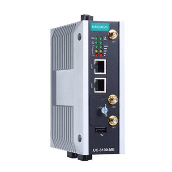
UC-8112-LX STK Hardware
Quick Installation Guide
First Edition, May 2015
Overview
The UC-8112-LX-STK is a starter kit that contains a UC-8100-LX
embedded computer, a Wi-Fi module, and a cellular module,
offering a complete solution for system evaluation. Users can
easily deploy the UC-8100-LX computer for wireless system
integration and development.
Package Checklist
Before installing the UC-8100, verify that the package contains the
following items:
UC-8112 Computer Kit
•
UC-8112-LX computer x 1
•
Console cable x 1
•
GPS antenna x 1
•
Cellular antenna x 1
•
Wi-Fi antenna x 1
•
DIN rail mounting kit x 1
•
1 GB SD x 1
•
Power jack x 1
•
Power adapter x 1
Wi-Fi Module Kit
•
Wi-Fi module x 1
•
Wi-Fi antenna cable x 1
Cellular Module kit
•
Cellular module x 1
•
Cellular antenna cable x 1
NOTE: Notify your sales representative if any of the above items
are missing or damaged.
Installing the UC-8100
There are two sliders on the back of the unit for DIN rail and wall
mounting.
– 1 –
Mounting on a DIN-Rail
Pull out the bottom slider, latch the unit onto the DIN-rail, and then
push the slider back in.
Mounting on the Wall
Pull out both the top and bottom
sliders and align the screws
accordingly.
Another method for wall mounting installation is to use the
optional wall mounting kit. Attach two mounting brackets on the
side panel of the computer, and fasten with screws. Install the
computer on a wall or cabinet by fastening two screws for each
bracket.
Connector Description
Power Connector
Connect the "terminal block to power jack converter" (in the
package) to the UC-8100's DC terminal block (located on the top
panel), and then connect the power adapter. It takes about 30
seconds for the system to boot up. Once the system is ready, the
Ready LED will light up.
– 2 –
Grounding the UC-8100
Grounding and wire routing help limit the effects of noise due to
electromagnetic interference (EMI).
SG: The Shielded Ground (sometimes
called Protected Ground) contact is
the top contact of the 3-pin power
terminal block connector when
viewed from the angle shown here.
Connect the SG wire to an
appropriate grounded metal surface.
Ethernet Ports
The two 10/100 Mbps Ethernet ports (LAN 1 and LAN 2) use RJ45
connectors.
Pin
Signal
1
ETx+
2
ETx-
3
ERx+
6
ERx-
Serial Ports
The two serial ports (P1 and P2) use terminal connectors. Each
port can be configured by software for RS-232, RS-422, or RS-485.
The pin assignments for the ports are shown in the following table:
Pin
RS-232
RS-422
RS-485
1
TXD
TXD+
---
2
RXD
TXD-
---
3
RTS
RXD+
D+
4
CTS
RXD-
D-
5
GND
GND
GND
SD/SIM Card Sockets
The UC-8100 comes with an SD socket for storage expansion, and
a SIM card socket for cellular communication. The SD card/SIM
card sockets are located at the lower part on the front panel. To
install them, remove the screw and the protection cover to access
the sockets, and then plug the SD card or the SIM card into the
sockets directly. You will hear "click" when finished. Remember to
push in on the SD card or SIM card first if you want to remove
them.
ATTENTION
By default, the operating system is stored on the SD card.
Do not remove the SD card while the computer is still
running.
– 3 –
Advertisement
Table of Contents

Related Manuals for Moxa Technologies UC-8112-LX STK


Summary of Contents for Moxa Technologies UC-8112-LX STK
- Page 1 Pull out the bottom slider, latch the unit onto the DIN-rail, and then Grounding and wire routing help limit the effects of noise due to push the slider back in. electromagnetic interference (EMI). UC-8112-LX STK Hardware SG: The Shielded Ground (sometimes called Protected Ground) contact is Quick Installation Guide...
- Page 2 Cellular Module 3. Install the other end of the cable onto the connector on the front panel of the UC-8100. Remove the black plastic cover The UC-8100 comes with a PCIe socket inside for wireless first. communication. Follow these steps: 4.
Need help?
Do you have a question about the UC-8112-LX STK and is the answer not in the manual?
Questions and answers