Sign In
Upload
Download
Table of Contents
Contents
Add to my manuals
Delete from my manuals
Share
URL of this page:
HTML Link:
Bookmark this page
Add
Manual will be automatically added to "My Manuals"
Print this page
×
Bookmark added
×
Added to my manuals
Manuals
Brands
Amico Manuals
Medical Equipment
ICE 25
Installation and operation instruction manual
Amico ICE 25 Installation And Operation Instruction Manual
Led surgical lights
Hide thumbs
1
Table Of Contents
2
3
4
5
6
7
8
9
10
11
12
13
14
15
16
17
18
19
20
21
22
23
24
25
26
27
28
29
30
31
32
33
34
35
36
37
38
39
40
41
42
43
44
45
46
47
48
49
50
51
52
53
54
55
56
57
page
of
57
Go
/
57
Contents
Table of Contents
Troubleshooting
Bookmarks
Table of Contents
Table of Contents
Introduction
Symbols Used in this Manual
Markings
Typical Drawings
Typical Drawings
Technical Data for Ice Lightheads
Installation Considerations
Tools and Part Requirements
Safety Instructions
Static Inspection
Declaration of Acceptance
Components and Scope of Delivery
Installation: Structure Plates and Flanged Ceiling Tube
Structure Plate and Anchor Plate
Order Components for each Threaded Rod
Installing the Flanged Ceiling Tube
Installation: the Central Axis
Installing the Ceiling Cover
Installation: Structure Plates and Flanged Ceiling Tube
Amico Ceiling Covers
Installing the Central Axis Core
Installing the Central Axis Arms
Installation: Electrical
Labelling of the Extension Leads
Routing the Extension Leads
Routing the Supply Lines through the Ceiling Tube
Grounding the Flange
Connecting the Power Supply
Installation: Electrical
Installation: Spring Arms
Standard Spring Arms on the Central Axis
Initial Setup
Installing/Removing the Spring Arm
Removing the Safety Plug
Installation: Amico Ice LED Light
Installing the Lighthead
Normal System/Lch with Camera
Installing in Light Camera (Optional Accessory)
Connecting the Camera Controller Box
Installation: Adjustments
Brake Adjustment
Installation/Removal of the Spring Arm
Load Adjustment
Parallel Adjustment
Vertical Adjustment
Installation: the Base Cap
Installation: Wiring Diagram
Terminal Block Usage
Normal Dual LED Configuration
Dual LED Configuration with Wall Control
Camera and Camera Ready Configuration with Wall Control
Installation: Wiring Diagram
Operation: Amico Ice LED Light
Lighthead Control Panel
Wall Control Panel for Light
Emergency Shut down
Camera Control Box
Emergency Bypass Switch
Beam Size Adjustment
Operation: Cleaning the Amico Ice LED Light
Non-Sterilizable Handle (Plastic/Aluminum)
Lamp Housing, Protective Lens and Support System
Maintenance: Amico Ice LED Lights
Maintenance: OASYS Spring Arm
Troubleshooting
Environmental Conditions
Technical Data for OASYS Central Axis and Spring Arms
Electromagnetic Compliance Data for Ice Series
Electromagnetic Compliance Data for Ice Series
Disposal
Warranty
Advertisement
Quick Links
1
Typical Drawings
2
Installation: Adjustments
3
Brake Adjustment
4
Maintenance: Oasys Spring Arm
5
Maintenance: Amico Ice Led Lights
6
Troubleshooting
Download this manual
Installation and Operation Instructions
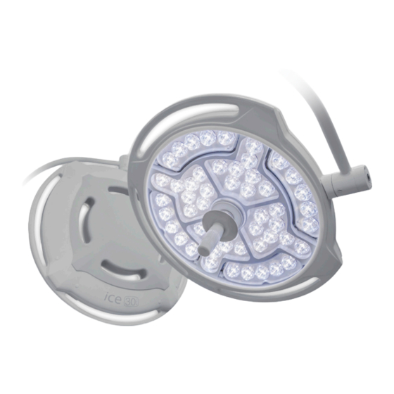
iCE LED Surgical Lights
(iCE 25/iCE 30)
w w w . a m i c o . c o m
Table of
Contents
Previous
Page
Next
Page
1
2
3
4
5
Advertisement
Table of Contents
Need help?
Do you have a question about the ICE 25 and is the answer not in the manual?
Ask a question
Questions and answers
Related Manuals for Amico ICE 25
Medical Equipment Amico ICE 30 Installation And Operation Instruction Manual
Led surgical lights (57 pages)
Medical Equipment Amico ICU Series Operation & Maintenance Manual
Bed (20 pages)
Medical Equipment Amico Roll Stand INE-0909-12-12-F4-M Installation Instructions Manual
Infusion extension arm (16 pages)
Medical Equipment Amico Apollo MS-SC Operation & Maintenance Manual
(48 pages)
Medical Equipment Amico AC-200C Operating & Maintenance Manual
Medical bed (12 pages)
Medical Equipment Amico GoLift Installation And Operation Instructions Manual
Patient lift (400 lbs & 700 lbs) (32 pages)
Medical Equipment Amico Falcon Installation Instructions Manual
Wall-mounted computer workstation (40 pages)
Medical Equipment Amico Majestic Series Installation Instructions Manual
Horizontal headwall single tier (8 pages)
Medical Equipment Amico ALERT- 2 Installation And Maintenance Manual
Economy manifold (19 pages)
Medical Equipment Amico Mira LED Exam Light Operating And Maintenance Instructions Manual
Wall mount (24 pages)
Medical Equipment Amico MRS Series Installation Instructions Manual
Equipment rail flanged cover (20 pages)
Medical Equipment Amico LightMaster Multifunction Switch Operating And Maintenance Instructions Manual
(20 pages)
Medical Equipment Amico S-H-300 Operation & Maintenance Manual
Hydraulic patient transfer stretcher (20 pages)
Medical Equipment Amico Diagnostic Station Instructions For Use Manual
(17 pages)
Medical Equipment Amico AC-400C Operation & Maintenance Manual
Hospital bed (12 pages)
Medical Equipment Amico Hummingbird HMA-PR-A-18 Installation Instructions Manual
Perch rail & accessories (18 pages)
This manual is also suitable for:
Ice 30
Table of Contents
Print
Rename the bookmark
Delete bookmark?
Delete from my manuals?
Login
Sign In
OR
Sign in with Facebook
Sign in with Google
Upload manual
Upload from disk
Upload from URL


Need help?
Do you have a question about the ICE 25 and is the answer not in the manual?
Questions and answers