Table of Contents
Advertisement
Quick Links
Advertisement
Table of Contents

Related Manuals for Amico Falcon


Summary of Contents for Amico Falcon
- Page 1 Installation Instructions Falcon Wall-Mounted Computer Workstation...
- Page 2 This Instruction Manual is your guide to ensure that you get the best performance out of the equipment. Amico Accessories is not responsible for any damage as a result of (but not limited to) abuse and other problems that may be a direct or indirect result of failure to comply with the instructions provided in this manual.
-
Page 3: Table Of Contents
7-15 Mounting to MRS (Monitor Rail System) OSHPD Anchor Pre-Approval OPA-1743 Mounting to VRS (Vertical Rail System) / Ohmeda Rail 10-11 Mounting to ARS (Amico Rail System) 12-13 Mounting to the Hill-Rom Vertical Rail 14-15 Section 3: Device Installation 16-23... -
Page 4: Section 1: Installation Preparation
3/16" (0.5 cm) or M4 Hex key/Allen key 1/8" (0.3 cm) or M3 Hex key/Allen key 12 mm (1.2 cm) Socket wrench 1/2" (0.05 cm) Socket wrench Adjustable wrench NOTE: Amico does not provide any display hardware, nor the tools necessary for assembly. Amico Accessories Inc. -
Page 5: Pre-Installation Information
DAMAGE TO THE ARM CAN OCCUR AS A RESULT OF OVERLOADING ARM ASSEMBLY. For installation on non-Amico rails, ensure the rail is safe for the application. If you are unsure about any part of the installation process or product use, please contact an Amico Accessories Product Specialist: 1-877-264-2697 Considerable efforts have been made to ensure the safety of your hospital staff and your patients. -
Page 6: Installation Reference
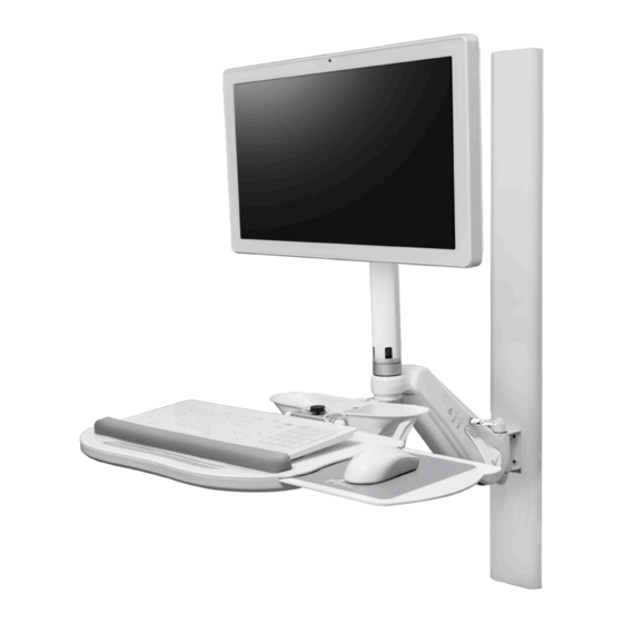
Section 1: Installation Preparation Installation Reference The picture below illustrates the components referenced in relation to one another in the installation of the Falcon Workstation. Please follow the instructions outlined herein to ensure proper installation. Falcon Workstation 1. LCD/Display Post (Page 32) For mounting and positioning of display. -
Page 7: Section 2: Installation On Rail Systems
Section 2: Installation on Rail Systems Installation Reference NOTE: This section assumes you are mounting your Falcon Workstation to an existing rail. If you need to mount rail for this installation, please download the appropriate rail installation manual via the link below or call 1-877- 264-2697 for assistance. -
Page 8: Mounting To Mrs (Monitor Rail System)
2. Engage the Height Locking Lever with the AHM Arm in the highest position. 3. Lift up the Falcon Workstation and guide the Mounting Adapter into the top of the MRS Rail (Figure 1). 4. Once the arm is positioned at the desired height in the MRS, tighten all four set screws to the tightest possible position on the Mounting Adapter using a 1/8"... -
Page 9: Oshpd Anchor Pre-Approval Opa-1743
In compliance with standards established for the anchor and installation of instrument support systems by the California Office of Statewide Health Planning and Development (OSHPD), Amico Accessories Inc. has obtained pre- approval for MRS 19" (48.3 cm) Wall Channels or longer with extension arm. For proper installation requirements please refer to our OPA Document. -
Page 10: Mounting To Vrs (Vertical Rail System) / Ohmeda Rail
TO VERIFY THAT NO MOVEMENT IS PRESENT BETWEEN THE ADAPTERS AND THE VRS. WARNING: ENSURE RAIL IS STABLE AND PROPERLY INSTALLED BEFORE MOUNTING FALCON WORKSTATION. WARNING: THE MOUNTING ADAPTER FOR OHMEDA RAILS DIFFER FROM THE MOUNTING ADAPTER FOR VRS, THE ADAPTERS ARE NOT CROSS-COMPATIBLE. - Page 11 1. Determine a suitable location on the VRS for the CPU, making sure it isn’t above a patient. Also ensure your CPU mount is compatible with your CPU’s weight and size rating. If not, please contact Amico Accessories 1-877-264- 2697.
-
Page 12: Mounting To Ars (Amico Rail System)
Once secure, release the lever (Figure 2). 2. Mount the Falcon Workstation by installing the remaining Mounting Adapter into the top ARS the same way as step 1, ensuring the two holes on the bottom Mounting Adapter can be seen through the Mounting Adapter Channel, secure the channel to the bottom Mounting Adapter using the screws and lock washers you removed in step 1 (Figure 3). - Page 13 WARNING: DO NOT INSTALL CPU MOUNT ABOVE PATIENT. WARNING: ENSURE RAIL IS STABLE AND PROPERLY INSTALLED BEFORE MOUNTING FALCON WORKSTATION. 1. Determine a suitable location on your ARS for the CPU mount, making sure it isn’t above the patient’s head.
-
Page 14: Mounting To The Hill-Rom Vertical Rail
NUTS ARE SECURED TO THE TIGHTEST POSSIBLE POSITION. AFTER INSTALLATION, ROTATE THE AHM ARM SIDE TO SIDE AND VERIFY NO MOVEMENT IS PRESENT BETWEEN THE ADAPTER AND THE RAIL. WARNING: REMOVAL OF LOCK NUTS WILL REQUIRE A NEW SET FOR REINSTALLATION. PLEASE CONTACT AMICO ACCESSORIES FOR SPARE PARTS, 1-877-264-2697. - Page 15 WARNING: ENSURE CPU IS WITHIN WEIGHT AND SIZE RATING OF THE CPU MOUNT. IF NOT, PLEASE CONTACT AMICO ACCESSORIES AT 1-877-264-2697. WARNING: REMOVAL OF LOCK NUTS WILL REQUIRE A NEW SET FOR REINSTALLATION. PLEASE CONTACT AMICO ACCESSORIES FOR SPARE PARTS AT 1-877-264-2697.
-
Page 16: Section 3: Device Installation
Display Mounting: VESA 75/100 WARNING: ENSURE THAT THE AHM ARM IS IN THE HIGHEST VERTICAL POSITION AND LOCKED BEFORE MOUNTING OR REMOVING DEVICES FROM THE FALCON WORKSTATION. NOTE: See page 25 for instructions on locking and unlocking the AHM Arm. -
Page 17: Display Mounting: For Displays Weighing 5.5 - 8 Lbs - Installing Weight Plate
Section 3: Device Installation Display Mounting: For 5.5-8 lbs Displays - Installation with Weight Plate WARNING: ENSURE THAT THE AHM ARM IS IN THE HIGHEST VERTICAL POSITION AND LOCKED BEFORE MOUNTING OR REMOVING DEVICES FROM THE FALCON WORKSTATION. PROJECT 0746 CUSTOMER DRAWING 1. -
Page 18: Mouse/Scanner Holder Installation
NOTE: See page 24 for instructions on locking and unlocking the AHM Arm. NOTE: The keyboard tray includes a mouse/scanner holder. The keyboard tray contains a sliding mouse tray with mouse pads. Amico Accessories also provides wrist rests and other accessories, however those must be purchased separately. -
Page 19: Keyboard And Mouse Mounting
Keyboard and Mouse Mounting 1. Place keyboard onto the keyboard tray, place the mouse into the mouse holder, ensure the end with the cable faces up. Follow cable management procedures to route the cables through the Falcon Workstation on pages 22-23. -
Page 20: Wrist Rest Mounting
Section 3: Device Installation Wrist Rest Mounting NOTE: Wrist rest is available but not provided with the Falcon Workstation by default. 1. To secure the wrist rest to a keyboard tray, use the dual locking coins provided. Follow the instructions on the previous page to attach the twelve (12) dual locking coins to the wrist rest. -
Page 21: Swapping Of Adaptor/Extension
4. The adapter/extension should come apart from the arm as shown on Figure 2. Check for any damaged thread. If you find any damage, don’t use that arm and please call Amico Accessories customer service. 5. Use new hardware provided with adaptor/extension in the package and reinstall with new screws in cross pattern (i.e. -
Page 22: Lcd/Display Post Cable Management
AHM Arm Cable Management NOTE: Falcon Workstation cable guide is provided to facilitate routing of cables along the bottom of the arm. NOTE: Longer cable guides are provided for arms with extensions. Guides also snap into grooves on the bottom of extension arms. -
Page 23: Mrs Rail Cable Management
NOTE: A MRS cable guide is available to facilitate routing of cables along the rails and is not provided by default with the Falcon Workstation. 1. Depending on where your CPU is mounted, guide the cables from the Falcon Workstation going to the CPU into the side of the channel leading to your CPU (Figure 1). -
Page 24: Section 4: Adjustments
1. Insert the height locking lever into the mounting hole on the side of the arm (Figure 1). Turn the lever clockwise to lock vertical movement, or turn the lever counterclockwise to release the vertical lock (Figure 2). Height Locking Lever: Rotate Counter-Clockwise to Release Rotate Clockwise to Lock Figure 1 Figure 2 Amico Accessories Inc. -
Page 25: Counterbalance
Tighten the locking lever again to lock the AHM Arm (Figure 1). 2. With the height locking lever disengaged, if the Falcon Workstation is drifting downwards, slowly loosen the counterbalance bolt, rotating counter-clockwise (Figure 2). If the Falcon Workstation is drifting upwards, slowly tighten the counterbalance bolt, rotating clockwise. -
Page 26: Portrait And Landscape Adjustment
Section 4: Adjustments Swivel (Falcon Workstation) Post Portrait and Landscape Rotation WARNING: MAKE THE ADJUSTMENTS WITH THE DISPLAY SECURELY MOUNTED. NOTE: To adjust the orientation, turn the display (Figure 1). Do not twist/tangle wires. 1. The Portrait and Landscape adjustment is done by holding the display and rotating 90 degrees. -
Page 27: Display Tilt And Pan
(Figure 2). ± 360° +10/-5° Keyboard base Small screws Screws for adjusting the swivel tension of Large screw the keyboard Nut for adjusting the swivel tension of the display Figure 1 Figure 2 www.amico.com 27... -
Page 28: Keyboard Tray Tilt Locking Knob
2. To decrease the angle of the keyboard, turn the knob counterclockwise, the keyboard tray should begin lowering on its own. Continue turning the knob until desired angle is achieved (Figure 1). Tray Tilt Locking Knob Lowers Raise Figure 1 Amico Accessories Inc. -
Page 29: System
NOTE: The following folding procedure assumes the Falcon Workstation is in the default arm position (Figure 1) and applies to both arms with extension and without. 1. Decide which side of the channel will be used to store the unit. Release the height locking lever on Falcon Workstation and raise it to the highest vertical position. - Page 30 180 degrees (Figure 2). 6. Rotational tension can be adjusted by tightening/loosening the bolts located at the joints of AHM Arm/extension arms. Remove the caps to access the bolt before adjusting (Figure 1). Caps Bolt Figure 1 Figure 2 Amico Accessories Inc.
-
Page 31: Panning And Articulation
WARNING: FOR FALCON WORKSTATION WITH EXTENSION ARMS, BOTH ARMS HAVE A 180 DEGREE ROTATION. ENSURE PROPER CLEARANCE AROUND THE ARM(S) TO AVOID COLLISION. NOTE: If the arm becomes difficult to rotate, or appears to be loose, please contact Amico Accessories: 1-877-264- 2697. -
Page 32: Falcon Workstation / Lcd/Display Post
Section 4: Adjustments Falcon Workstation / LCD/Display Post 1. The Swivel-post allows for 6.5" (16.5 cm) vertical adjustment of the display, independent from the keyboard tray. 2. To rotate the keyboard tray with the display simply rotate the keyboard tray and the display will rotate along with it. -
Page 33: Spring Adjustment
4. Replace the VESA Head, re-attach the top plate with the screws and replace the cap and the LCD/Display Post cover. Top Cover Top Plate VESA Plate HEX Nut Gas Spring Swivel-Post Screws LCD/Display Post Cover Figure 1 Figure 2 www.amico.com 33... -
Page 34: Section 5: Troubleshooting, Maintenance And Product Classification
• Display drifts down/AHM Arm drifts down • Damaged or incorrect Gas spring in AHM Please contact Amico Accessories Arm/LCD/Display Post If the above solutions do not solve your symptoms or you are in need of parts/hardware, please contact Amico Accessories, 1-877-264-2697 Amico Accessories Inc. -
Page 35: Preventive Maintenance (Falcon Workstation)
SHOULD BE MORE FREQUENT FOR HIGHER USE AREAS. Please be sure to thoroughly check the areas illustrated below for Falcon Workstation: If the above solutions do not solve your symptoms or you are in need of parts/hardware, please contact Amico Accessories, 1-877-264-2697... - Page 36 B) Support the AHM Arm and unlock the height adjustment lever then inspect counter balance to ensure device weight is still supported throughout range of motion (refer to Section 4: Adjustments, Counterbalance: Falcon Workstation page 25). Area 4: CPU Mount A) Ensure the two set screws on the channel and two thumb screws are fastened to the tightest possible Position.
-
Page 37: Part Number Matrix
Track Adapter Device Load/Weight Keyboard Tray White 5.5-8 lbs (2.5-3.6 kg) Load on VESA Mount Monitor Channel Falcon 7.5-10 lbs (3.4-4.5 kg) Load on VESA Mount Custom 13-15.5 lbs (5.8-7 kg) Load on VESA Mount Mini *Amico Horizontal 10-13lbs (5.8kg) Load on VESA Mount +... -
Page 38: Cleaning
Dry the arm thoroughly after cleaning. No Acetone No Trichloroethylene Acetone is a colorless, mobile, Trichloroethylene is a chlorinated flammable liquid hydrocarbon commonly used as an industrial solvent Acetone Trichloroethylene Figure 1 Figure 2 Amico Accessories Inc. -
Page 39: Warranty Information
Amico Accessories Inc. will warrant its materials to be free from defect for an additional period of four (4) years, (five [5] years from the date of shipment). Within this period, Amico Accessories Inc. will replace any part which is proven to be defective, at no charge. - Page 40 Amico Accessories Inc. | 85 Fulton Way, Richmond Hill, ON L4B 2N4, Canada Toll Free Tel: 1.877.264.2697 | Tel: 905.763.7778 | Fax: 905.763.8587 Email: info@amico-accessories.com | www.amico.com AMICO-AA-WALL-MOUNTED-COMPUTER-WORKSTATION-FALCON-MANUAL 06.01.2021...
Need help?
Do you have a question about the Falcon and is the answer not in the manual?
Questions and answers