Graco Fire-Ball 203872 Instructions-Parts List Manual
5:1 ratio pumps
Hide thumbs
Also See for Fire-Ball 203872:
- Instructions manual (16 pages) ,
- Instructions manual (16 pages) ,
- Installation and operations (34 pages)
Advertisement
Table of Contents
- 1 Table of Contents
- 2 Warnings
- 3 Installation
- 4 Operation
- 5 Troubleshooting
- 6 Air Motor and Throat Service
- 7 Displacement Pump Service
- 8 Air Motor Parts List
- 9 Air Motor Parts Drawing
- 10 Pump Parts Drawing
- 11 Pump Parts List
- 12 Technical Data
- 13 Pump Models and Dimensional Drawings
- 14 Mounting Hole Layout
- 15 Graco Standard Warranty
- 16 Graco Phone Number
- Download this manual
Parts
INSTRUCTIONS-PARTS LIST
INSTRUCTIONS
5:1 Ratio Fire-BallR Pumps
900 psi (6.2 MPa, 62 bar) Maximum Working Pressure
180 psi (1.2 MPa, 12 bar) Maximum Air Input Pressure
Oil Pumps
These pumps are designed to pump lubricating
fluids only.
See page 19 for pump Model Numbers.
Table of Contents
. . . . . . . . . . . . . . . . . . . . . . . . . . . . . . . . . . . . . .
. . . . . . . . . . . . . . . . . . . . . . . . . . . . . . . . . . . . .
. . . . . . . . . . . . . . . . . . . . . . . . . . . . . . . . . . . . .
This manual contains important
warnings and information.
READ AND KEEP FOR REFERENCE.
CAUTION
. . . . . . . . . . . . . . . . . . . . . . . . . . . . . . . .
. . . . . . . . . . . . . . . . . . . . . . . . . .
. . . . . . . . . . . . . . . . . . . . . . . . . . . . . . .
. . . . . . . . . . . . . . . . . . . .
. . . . . . . . . . . . . . . . . . . .
. . . . . . . . . . . . . . . . . . . . . . . . . . . .
. . . . . . . . . . . . . . . . . . . . . . . .
. . . . . . . . . . . . . . . . . . . . . . . . . . .
. . . . . . . . . . . . . . . . . . . . . . . . . . . . . . .
. . . . . . . . . . . . . . . . . . . . . .
. . . . . . . . . . . . . . . . . . . . . . . . . .
GRACO INC. P.O. BOX 1441 MINNEAPOLIS, MN 55440-1441
ECOPYRIGHT 1994, GRACO INC.
Graco Inc. is registered to I.S. EN ISO 9001
Model 203876
2
18
. . . . . . . . .
19
19
5
8
10
11
15
16
16
17
17
20
20
306518
First choice when
quality counts.t
Models 203872
05750
Rev. V
203857
204254
222087
05751
Advertisement
Table of Contents

Subscribe to Our Youtube Channel
Related Manuals for Graco Fire-Ball 203872


Summary of Contents for Graco Fire-Ball 203872
-
Page 1: Table Of Contents
......05751 GRACO INC. P.O. BOX 1441 MINNEAPOLIS, MN 55440–1441 ECOPYRIGHT 1994, GRACO INC. Graco Inc. is registered to I.S. EN ISO 9001... -
Page 2: Warnings
D Read all instruction manuals, tags, and labels before operating the equipment. D Use the equipment only for its intended purpose. If you are not sure, call your Graco distributor. D Do not alter or modify this equipment. Use only genuine Graco parts and accessories. - Page 3 WARNING WARNING FLUID INJECTION HAZARD Fluid from the dispensing valve, leaks, or ruptured components can inject fluid into your body and cause extremely serious injury, including the need for amputation. Fluid splashed in the eyes or on the skin can also cause serious injury. D If a fluid injection injury occurs, get emergency medical care at once.
- Page 4 WARNING WARNING FIRE AND EXPLOSION HAZARD Improper grounding, poor ventilation, open flames or sparks can cause a hazardous condition and result in a fire or explosion and serious injury. D Ground the equipment and the object being lubricated. See Grounding on page 7. D If there is any static sparking or you feel an electric shock while using this equipment, stop dispensing immediately.
-
Page 5: Installation
The typical installation shown in Fig. 1 is only a guide for selecting and installing a pump; it is not an actual system design. Contact your Graco distributor for assistance in designing a system to suit your needs. DETAIL A 1/2 in. - Page 6 Installation 1. Install the pump on the drum cover so that the CAUTION pump’s fluid intake is 1/2 in. (13 mm) off the bottom of the drum, as shown in Fig. 1. Always mount the pump firmly to a bracket or a tank cover.
- Page 7 Installation Grounding Proper grounding is an essential part of maintaining a To ground the pump , loosen the grounding lug safe system. locknut (W) and washer (X). Insert one end of a 12-gauge (1.5 mm@) minimum ground wire (Y) into the To reduce the risk of static sparking, ground the pump.
-
Page 8: Operation
Operation Pressure Relief Procedure Starting and Adjusting the Pump WARNING WARNING PRESSURIZED FLUID HAZARD MOVING PARTS HAZARD The equipment stays pressurized until Never operate the pump with the warn- pressure is manually relieved. To re- ing plate (20) or the identification plate duce the risk of serious injury from (18) removed. - Page 9 Operation 5. If your pump accelerates quickly or is running too 6. Read and follow the instructions supplied with fast, stop it immediately and check the fluid supply. each component in your system. If the supply container is empty and air has been 7.
-
Page 10: Troubleshooting
Troubleshooting NOTE: Check all other possible problems and solutions before disassembling the pump. Problem Cause Solution Pump fails to operate Inadequate air supply pressure or Increase air supply; clear restricted air lines Closed or clogged dispensing Open; clear valve Clogged fluid lines, hoses, valves, Clear etc. -
Page 11: Air Motor And Throat Service
Air Motor and Throat Service Before You Start CAUTION D Be sure you have all necessary parts on hand. Do not damage the plated surface of the trip rod Pump Repair Kit 238286 includes repair parts for (11). Damaging the surface of the trip rod can the pump and air motor. - Page 12 Air Motor and Throat Service 12. Remove the o-ring (24*) from the air motor Reassembly piston (2). 1. Clamp the displacement rod (8) upright in the vice by closing the vice jaws on the flats of the 13. Clamp the displacement rod upright in the vice by displacement rod.
- Page 13 Air Motor and Throat Service Cutaway View 04119 04118 Push toggles (M) in and then up. Cut off tops of poppets as indicated by dotted lines. Turn wires up. 0.145 in. (3.7 mm) clearance between poppets (1*) and seat when it is open. Fig.
- Page 14 Air Motor and Throat Service 17. Grip the trip rod (11) with padded pliers, screw the CAUTION cylinder cap nut (29) onto the trip rod, push the cylinder cap nut down, and screw it into the top of Never re-use the old lock wires. They will get the cylinder.
-
Page 15: Displacement Pump Service
Displacement Pump Service Before You Start 5. Using wrenches on the flats of the displacement rod (8) and on the flats of the fluid piston (110), Be sure you have all necessary parts on hand. Pump unscrew the fluid piston from the displacement rod. Repair Kit 238286 includes repair parts for the pump and air motor. -
Page 16: Air Motor Parts List
Air Motor Parts List Air Motor Parts Drawing All Models Ref. Part No. Description Qty. 236079 POPPET, valve 160614 PISTON, air motor 238278 BASE, air motor (includes 5a to 5c) 104582 .WASHER, tab 104029 .LUG, grounding 180233 .LABEL, warning 112561 PACKING, u-cup 191124 ROD, displacement... -
Page 17: Pump Parts Drawing
Pump Parts Pump Parts List Drawing Model 203857, Series L Includes items 101 to 114. Model 203872, Series L Includes items 101 to 113 and 115. Model 203876, Series L Includes items 101 to 112. 112* Model 204254, Series P Includes items 101 to 113, 116, and 118. -
Page 18: Technical Data
Technical Data Maximum working pressure ....900 psi Pump cycles per gallon (per liter) ... 30 (7.9) 6.2 MPa, 62 bar) Maximum recommended... -
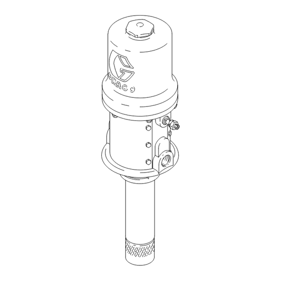
Page 19: Pump Models And Dimensional Drawings
Pump Models and Dimensional Drawings Model 203857, Series L Model 203876, Series L Universal, wall mount 55-gal. (400 lb) drum size, cover mount Overall Length: 45.6 in. (1158 mm) Model 203872, Series L 16-gal. (120 lb) drum size, cover mount Overall Length: 38.1 in. -
Page 20: Graco Standard Warranty
Graco distributor to the original purchaser for use. With the exception of any special, extended, or limited warranty published by Graco, Graco will, for a period of twelve months from the date of sale, repair or replace any part of the equipment determined by Graco to be defective.
Need help?
Do you have a question about the Fire-Ball 203872 and is the answer not in the manual?
Questions and answers