Rath Command Center Installation & Operation Manual
Hide thumbs
Also See for Command Center:
- Installation & operation manual (12 pages) ,
- Installation & operation manual (12 pages) ,
- Installation & operation manual (8 pages)

Related Manuals for Rath Command Center


Summary of Contents for Rath Command Center
- Page 1 Installation & Operations Manual Command Center N56W24720 N. Corporate Circle Sussex, WI 53089 RP8500PBXG Made in the USA Ver. 3 800-451-1460 www.RATHCommunications.com 3 Year Warranty 10/18...
-
Page 2: Table Of Contents
Thank you for purchasing RATH’s Command Center. We are the largest Emergency Communication Manufacturer in North America and have been in business for over 35 years. We take great pride in our products, service, and support. Our Emergency Products are of the highest quality. -
Page 3: Items Needed
Distribution Module and Power Supply is in a network closet or machine room. Mount the Command Center according to the owner’s specifications. Follow the diagram below for attaching the extender and foot stand to the back of the Command Center phone as needed. -
Page 4: Typical System Layout
• These instructions apply for connecting the Command Center to the Distribution Module as well as for connecting Emergency Phones to the Distribution Module. • The maximum cable run to the Distribution Module from the Command Center is 6,200’ for 22 AWG and 3,900’ for 24 AWG cable. - Page 5 Note: When using the Command Center for non-elevator applications, it is recommended to use a biscuit jack for connecting each phone. The communication wire pair should be connected to the red and green screw terminals on the biscuit jack. This will prevent loose connections that can cause the system to malfunction.
- Page 6 • S01-S_ is the port used for connecting Emergency Phones • TD(1-2)(3-4) with a dot under the D is the port used for connecting Command Center phone(s) • TD(1-2)(3-4) with a dot under the T is the port used for outside Telco Line •...
- Page 7 Card 2 Example Step 4: Apply AC power to the Distribution Module by connecting the supplied power cable from the Distribution Module to the RATH® model RP7700104 or RP7701500 Power Supply. Step 5: Turn on the Power Supply. Step 6: Turn on the Distribution Module.
-
Page 8: Setting The Date And Time
The Phones are pre-programmed for Memory Location 1 to dial 3931 in order to call the Command Center first. The Phone can be programmed to dial an outside number if the call is not answered at the Command Center (optional). -
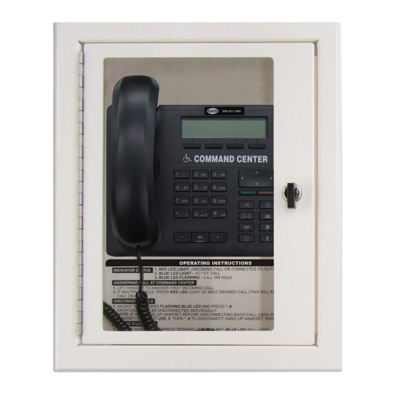
Page 9: Operating Instructions
• To adjust the volume on 2400 Phones, use the VOL key. Lights continuously blink on • The phone is not properly hung up. Lift the Command Center handset, select button for Emergency Phone: the blinking light, then hang up the handset.
Need help?
Do you have a question about the Command Center and is the answer not in the manual?
Questions and answers