Table of Contents

Subscribe to Our Youtube Channel
Related Manuals for Rath Refuge Command Center


Summary of Contents for Rath Refuge Command Center
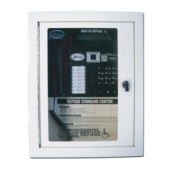
- Page 1 Installation & Operations Manual Refuge Command Center RP8500PBX N56 W24720 N. Corporate Circle Sussex, WI 53089 Rev. 3 Made in the USA 800-451-1460 262-246-4828 (fax) 12/13 3 Year Warranty www.rathmicrotech.com www.area-of-refuge.com...
- Page 2 Thank you for purchasing the Rath Refuge Command Center. We take great pride in our products, service and support. Our #1 mission is customer satisfaction. When evaluating emergency communication systems, you can rely on Rath to continually provide Innovative Thinking, Design and Value.
- Page 3 3. Take one end of the Distribution Module Power Cable and Plug it into the DC Adapter Port on the Distribution Module and the other end into a 110 volt AC outlet with Battery Backup or the Rath Model RP7700104 (12-36 Zone) or Model RP7700105 (56-112 Zone).
- Page 4 Distribution Module Programming *Note: All programming for the Distribution Module will be done from the Base Station Handset. Programming Time Zone 1. Enter programming mode A. Dial 1#91 B. Enter Password: 7284 2. 1002 (time zone code) Eastern Central Mountain 113 Pacific 3.
- Page 5 Phone Programming Connect the Phone to an active Port on Distribution Module and follow the instructions below Phone Calls the Base Station 1. For the Phone to call the Base Station, it must be programmed to dial 0 2. Follow the directions that came with the Phone to program Memory Location 1 to dial 0 Phone Calls a Number Outside of the Building 1.
- Page 6 HELP PHONE SOLID LIGHT: CALLING BLINKING LIGHT: RECEIVED Base Station HELP PHONE SOLID LIGHT: CALLING BLINKING LIGHT: RECEIVED 1 Wire Pair Per Phones Distribution Module HELP PHONE SOLID LIGHT: CALLING BLINKING LIGHT: RECEIVED Power Supply w/UPS HELP PHONE SOLID LIGHT: CALLING BLINKING LIGHT: RECEIVED pg.
- Page 7 Card Wiring for 12-36 Zone System A. On back of unit, remove two screws in top left and right and slide cover off unit to expose internal cards. B. On top of each card there is a table indicating what each port on that card is. 1.
- Page 8 Card Wiring for 56-112 Zone System A. Each card installed in 56-122 zone units will have 6 ports on each card. B. Each slot is labeled below indicating what type of slot it is. 1. S00-S00 is the port(s) used for connecting Emergency Phones 2.
Need help?
Do you have a question about the Refuge Command Center and is the answer not in the manual?
Questions and answers