
Related Manuals for Compliance West HT-10KVDC


Summary of Contents for Compliance West HT-10KVDC
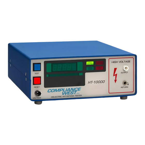
- Page 1 HT-10KVDC Dielectric Withstand Tester 0-14000 Volts DC Output Instruction Manual COMPLIANCE WEST...
- Page 3 To fully appreciate all the features of your new meter, we suggest that you take a few moments to review this manual. Compliance West USA stands by your instrument with a full one- year warranty and a loaner instrument policy. If the need arises, please don't hesitate to call on us.
-
Page 5: Table Of Contents
Table of Contents Initial Setup ........................2 An Introduction to Dielectric Withstand Testing with the HT-10KVDC........3 Leakage Test ........................3 High Voltage Dielectric Withstand Test................ 3 High Voltage Discharge ..................4 Introduction ........................5 Specifications ......................... 5 Operation............................. 7 Setting up the HT-10KVDC................... -
Page 7: Initial Setup
HT-10KVDC to conduct actual testing. Initial Setup 1. Remove the HT-10KVDC from its shipping carton and set it up on a bench. Plug it in to a correctly rated source of supply, using the supplied cordset. Turn it on using the switch on the rear panel. -
Page 8: An Introduction To Dielectric Withstand Testing With The Ht-10Kvdc
The HT-10KVDC will provide full voltage at any leakage current level up to 5 mA DC. The leakage current trip level is adjustable on the rear panel. -
Page 9: High Voltage Discharge
"Hipot Pass" light or the red "Hipot Fail" light on the front panel is lit, and the output voltage, as indicated on the front panel meter, drops to a safe level. This indicates that the HT-10KVDC output voltage has discharged to a safe level and there is no energy stored in the circuit. -
Page 10: Introduction
The instrument is a bench-type Dielectric Withstand Tester with DC Output, designed for laboratory testing of components and insulation systems. The HT-10KVDC features automatic one button operation, with numerous safety features designed to protect the operator: The Return Lead is directly connected to ground potential for operator safety. - Page 11 ENVIRONMENTAL Operating Temperature 15-40°C Relative Humidity Range 0-90% non-condensing GENERAL Input power requirements Model HT-10KVDC: 114-127 volts, 50/60 Hz Weight 22 lbs. RESET and TEST Lamp Type Replace with type 73 14V lamp. SAFETY AGENCY TOPICS Transformer Output < 500VA...
-
Page 12: Operation
Remove the Tester from its container and place it on a test bench. AC Line Voltage Requirements Connect the HT-10KVDC only to the voltage source per the rating on the rear panel. Fuse Replacement There is a user-replaceable fuse (F1) located on the rear panel. The fuse rating is on the rear panel. -
Page 13: Front And Rear Panel Features
Front and Rear Panel Features The front panel features of the HT-10KVDC are shown in Figure 3-1 and described in Table 3-1. The rear panel features of the HT-10KVDC are shown in Figure 3-2 and described in Table 3-2. - Page 14 Figure 3-1. Controls, Indicators, Connectors - HT-10KVDC Front Panel...
- Page 15 73 T1¾ 14V lamp. TEST Button / When lit, indicates that the HT-10KVDC is ready to test. The blue lamp goes out when the TEST Blue Indicator Lamp Button is pressed. Replace lamp with type 73 T1¾ 14V lamp.
- Page 16 Figure 3-2. Controls, Indicators, Connectors - HT-10KVDC Rear Panel...
- Page 17 Specifies replacement fuse and supply voltage used. Rating of supply Failure Shutdown Switch (not When in ON position, a leakage or dielectric failure will terminate the test. as shown) When in DEFEAT position, test will continue. Table 3-2. Control, Indicators, Connectors - HT-10KVDC Rear Panel...
-
Page 18: Initial Checkout Procedure
9. At test termination, the Excess Leakage and/or Hipot Fail lamps; items 3 and 5, and red RESET lamps should be lit. 10. Disconnect the black lead from the red lead, and remove both leads from the HT-10KVDC. 11. Enable the voltage output by pressing the RESET button, then the TEST button. After the full voltage LED lights, adjust the Voltage knob;... -
Page 19: Factory Settings
Factory Settings The HT-10KVDC is configured as shown when shipped from Compliance West USA: Leakage Current Level: 2 mA High Voltage Ramp Time: 1 second High Voltage Level: 0 volts High Voltage Test Time: 2 seconds Voltage Ramp Switch: Test Timer Switch:... -
Page 20: Adjustment Of The High Voltage Ramp Time
This procedure sets the amount of time the tester will conduct the high voltage test. The test duration of the HT-10KVDC is factory set for 2 seconds. If a different test duration is required, use this procedure to set it. -
Page 21: Setting The Voltage Ramp Switch
2, is pushed. The minimum test time is approx. 1 second. When this switch is in the ON position, the test time will be controlled by the HT-10KVDC's internal timer. For information on how to set this time, see instructions above. -
Page 22: Daily Operation Test
HT-10KVDC will continue to test. Voltage output may sag if the power required by the circuit is beyond the capabilities of the HT-10KVDC. If the Test Timer Switch; item 12, is ON, the HT-10KVDC will conduct the high voltage •... -
Page 23: Test Results
Test results Hipot Pass: If the Hipot Pass light is lit, the equipment being tested passed all test parameters. Red LED/Buzzer: Any red LED/buzzer test result means the equipment being tested failed a test phase. If unanticipated test failures continue, and you suspect that the equipment under test is built correctly, check the following item: If the Leakage Current level is at its highest setting and failures continue, check the circuit being tested with an ohmmeter;... - Page 24 Voltage Ramp DEFEAT DEFEAT DEFEAT Test Timer DEFEAT DEFEAT DEFEAT Failure Shutdown DEFEAT See Below Table 3-3: Rear Panel Switch Truth Table...
- Page 25 Total Defeat. Full voltage is produced at the output immediately. Test will continue only as long as the TEST button is held in, minimum one second. The HT-10KVDC will not shut down on a leakage or dielectric failure, but the front panel Excess Leakage or Hipot Fail lights will indicate a failure.
-
Page 26: Technical Assistance
Technical Assistance For Technical Assistance Phone: (800) 748-6224 Technical Assistance is available from Compliance West USA between the hours of 8:30 AM and 4:30 PM Pacific Time. Compliance West USA 2120 Jimmy Durante Blvd., Suite 118 Del Mar, CA 92014... -
Page 27: Maintenance And Calibration
0-14000 Vdc ± 1%. Service Information The HT-10KVDC is warranted to the original purchaser for a period of 1 year. This warranty does not cover problems due to misuse or neglect. Malfunctions which occur within the limits of the warranty will be corrected at no charge. Mail the instrument post paid to the manufacturer. -
Page 28: Cleaning
9. At test termination, the Excess Leakage and/or Hipot Fail lamps; items 3 and 5, and red RESET lamps should be lit. 10. Disconnect the black lead from the red lead, and remove both leads from the HT-10KVDC. 11. Enable the voltage output by pressing the RESET button, then the TEST button. After the full voltage LED lights, adjust the Voltage knob;... -
Page 29: Calibration Procedure
with a buzzer. The Full Voltage, Hipot Fail and/or Excess Leakage, and red RESET lamps should be lit. With the exception of lamp replacement of the TEST and RESET buttons with type 73 14 volt lamps, if the results of the performance test are not in accordance with the above, service is required.
Need help?
Do you have a question about the HT-10KVDC and is the answer not in the manual?
Questions and answers