
Related Manuals for Rose electronics Orion XTender OT2-SLDTXUD1D


Summary of Contents for Rose electronics Orion XTender OT2-SLDTXUD1D
- Page 1 Orion XTender Modular CATx/Fiber Extender • 2/4/6/21-Card Chassis Installation Operation Manual 10707 Stancliff Road Phone: (281) 933-7673 Houston, Texas 77099 techsupport@rose.com...
- Page 2 LIMITED WARRANTY Rose Electronics warrants the Orion XTender to be in good working order for one year from the date of purchase from Rose Electronics or an authorized dealer. Should this product fail to be in good working order at any time during this one-year warranty period, Rose Electronics will, at its option, repair or replace the Unit as set forth below.
- Page 3 This is to certify that, when installed and used according to the instructions in this manual, together with the specified cables, the Orion XTender units listed in this manual are shielded against the generation of radio interferences in accordance with the application of Council Directive 2014/30/EU and 2014/35/EU as well as these standards: EN 55022: 2010/AC:2011 (Class A) EN 55024:2010 + A1:2015...
-
Page 4: Table Of Contents
TABLE OF CONTENTS Contents Page # Disclaimer System Introduction Features Compatibility Package contents System Overview Orion XTender Models Orion Xtender Chassis Types Orion XTender Card Types DVI Cards 1 x Single-Link DVI-D Cards 1 x Dual-Link DVI-D Cards 2 x Single-Link DVI-D Cards 1 x DVI-I (VGA) Cards HDMI Cards 1 x HDMI Video-Only Cards... - Page 5 Digital Audio Only Embedded Upgrade Card USB-HID Only Embedded Upgrade Card USB 2.0 Only Embedded Upgrade Card Standalone Upgrade Cards First Generation USB 2.0 Standalone Upgrade Card Second Generation USB 2.0 Standalone Upgrade Card Operation Transmission Parameters Command Mode DDC Settings Downloading DDC Information from Console Monitor Working with the DDC Information File USB-HID Ghosting...
- Page 6 Figure 11. HDMI Cards: 1 x HDMI with Local Video Out Cards Figure 12. HDMI Cards: 1 x HDMI with Local Video Out and Redundant Link Cards Figure 13. Standalone Upgrade Cards: USB 2.0 Figure 14. Embedded Upgrade Cards with USB-HID Figure 15.
- Page 7 Tables Page # Table 1. Compatible Devices Table 2. Video Card LEDs: LED 1 and 2 - Connection Status Table 3.Video Card LEDs: LED 3 & 4 (on Dual-Head / Dual-Link Card Only) - USB and Video Status 41 Table 4. HDMI Video Card LED: LED 4 - Locally Connected Source Status Table 5.
- Page 8 Table 45. Mini USB Type B Connector Pinouts Table 46. PS/2 Connector Pinouts Table 47. RJ45 Connector Pinouts Table 48. Fiber SFP Type LC Connector Pinouts Table 49, Power Supply Connector Pinouts Table 50. D-Sub 9 (Serial) RS232 Connector Pinouts Table 51.
- Page 9 Digital Audio Interface Interconnect Cable CATx Fiber Supported Peripherals USB-HID Devices USB 2.0 Devices Connector Pinouts Video Connectors DVI-D and DVI-I Single-Link Connector DMS-59 Dual-Link Connector HDMI Connector HID Connectors USB Type A Connector USB Type B Connector Mini USB Type B Connector PS/2 Connector Interconnect Connectors RJ45 (CATx) Connector...
-
Page 10: Disclaimer
System Introduction Thank you for choosing the Rose Electronics Orion XTender, a high-performance, long distance, multi- function digital KVM Extender. The product increases the distance between a source (computer, CPU) and its console (display, keyboard, mouse, and other peripheral devices). -
Page 11: Compatibility
Compatibility Computers PCs (all operating systems) Displays DVI-D or HDMI video to 1.65 Gbit/sec/channel Keyboards All standard USB keyboards Mouse All standard USB mice Serial Compatible devices up to 19.2KBaud Audio Bi-directional CD quality stereo audio USB 2.0 devices Table 1. Compatible Devices Package contents Orion XTender pair (Transmitter unit and Receiver unit) 1x 5VDC international power supply unit per unit, 2x for units with redundancy option... - Page 12 DVI and HDMI Transmitters with embedded USB 2.0 only: 5.9 ft (1.8 m) USB cable, Type A to Type B DVI and HDMI Transmitters with USB 2.0 upgrade module only: 5.9 ft (1.8 m) USB cable, Type A to Type If any of the above is missing, please contact Rose Electronics. Optional: Additional DVI, USB, Audio and Serial cables for CPU-to-Transmitter connections can be ordered separately.
-
Page 13: System Overview
OVERVIEW System Overview The Orion XTender consists of at least one Transmitter unit and one Receiver unit. The Transmitter unit is installed at the local site, and the Receiver unit is installed at the remote site. At the local site, the Transmitter module is connected directly to the source (computer, CPU) using the supplied cables. -
Page 14: Orion Xtender Models
MODELS Orion XTender Models The Orion Xtender is a customizable product suitable for a wide variety of extension needs. Several types of cards are available which can be fitted in one of eight chassis types. The cards can be mixed and matched in a desired chassis to get the ideal combination for the user’s requirements. -
Page 15: Orion Xtender Card Types
Orion XTender Card Types Orion XTender cards are available with DVI or HDMI video input and output. DVI Cards DVI cards come with a variety of options: 1 single-link DVI-D, 1 dual-link DVI-D, 2 single-link DVI-D, or 1 DVI-I (VGA option). All these cards are available with either CATx or single-mode fiber interconnects. 1 x Single-Link DVI-D Cards Transmitters Receivers... -
Page 16: 1 X Dual-Link Dvi-D Cards
Transmitters Receivers With USB HID, Redundant Link, Fiber Part #: OEC-SLD2SUD1D/IRK Part #: OEC-SRD2SUD1D/IRK 1. Service port 1. Service port 2. Fiber port 1 2. Fiber port 1 3. Fiber port 2 3. Fiber port 2 4. To CPU: USB-HID 4. -
Page 17: 2 X Single-Link Dvi-D Cards
2 x Single-Link DVI-D Cards Transmitters Receivers With USB HID, CATx Part #: OEC-SLDTXUSL1/IRK Part #: OEC-SRDTXUSL1/IRK 1. Service Port 1. Service port 2. CATx Port 2. CATx port 3. To CPU: USB-HID 3. To USB-HID devices 4. To CPU: DMS-59 to Dual-Head DVI 4. -
Page 18: 1 X Dvi-I (Vga) Cards
1 x DVI-I (VGA) Cards Transmitters Receivers With USB HID, CATx Part #: OEC-SLDTXUS1V/IRK Part #: OEC-SRDTXUS1V/IRK 1. Service Port (KVM) 1. Service port 2. CATx Port 2. CATx port 3. To CPU: USB-HID 3. To USB-HID devices 4. To CPU: DVI-I (VGA / DVI) 4. -
Page 19: Hdmi Cards
HDMI Cards DVI cards come in a variety of options: video-only, video with USB HID, with local video out and with a redundant link. In addition, all these options are available with either CATx or single-mode fiber interconnects. 1 x HDMI Video-Only Cards Transmitters Receivers Video Only, CATx... -
Page 20: 1 X Hdmi With Usb Hid Cards
1 x HDMI with USB HID Cards Transmitters Receivers With USB HID, CATx Part #: OEC-SLDTXUH1H/IRK Part #: OEC-SRDTXUH1H/IRK 1. Service Port 1. Service Port 2. CATx Port 2. CATx Port 3. CPU: USB-HID 3. CPU: USB-HID 4. To CPU: HDMI 4. -
Page 21: 1 X Hdmi With Redundant Link Cards
1 x HDMI with Redundant Link Cards Transmitters Receivers With USB HID and Redundant Link, CATx Part #: OEC-DLD2CUH1H/IRK Part #: OEC-SRD2CUH1H/IRK 1. Service Port 1. Service Port 2. CATx Port1 2. CATx Port 1 3. CATx Port 2 3. CATx Port 2 4. -
Page 22: 1 X Hdmi With Local Video Out Cards
1 x HDMI with Local Video Out Cards Transmitters Receivers With USB HID and Local Video Out, CATx Part #: OEC-DLDTXUH1H/IRK Part #: OEC-DRDTXUH1HW/IRK 1. Service Port 1. Service Port 2. CATx Port 2. CATx Port 3. CPU: USB-HID 3. USB-HID devices 4. -
Page 23: 1 X Hdmi With Local Video Out And Redundant Link Cards
1 x HDMI with Local Video Out and Redundant Link Cards Transmitters Receivers With USB HID, Local Video Out and Redundant Link, CATx Part #: OEC-DLD2CUH1H/IRK Part #: OEC-DRD2CUH1HW/IRK 1. Service Port 1. Service Port 2. CATx Port 1 2. CATx Port 1 3. -
Page 24: Standalone Upgrade Cards
Standalone Upgrade Cards Standalone Upgrade cards are cards that provide specific functionality. They have interconnect ports, and can be installed independently of other cards. The Orion Xtender has a USB 2.0 upgrade card with CATx or single- mode fiber interconnect. Transmitters Receivers USB 2.0, CATx... -
Page 25: Embedded Upgrade Cards
Embedded Upgrade Cards Embedded Upgrade cards are cards that provide additional functionality. Unlike the standalone Upgrade cards, they do not have interconnect ports, and are not meant to be used by themselves. They are stacked on top of the DVI and HDMI video cards to provide additional functionality such as analog audio, digital audio, USB 2.0, serial or PS/2. -
Page 26: Embedded Upgrade Cards With Usb 2.0
Embedded Upgrade Cards with USB 2.0 Transmitters Receivers USB 2.0 Only Part #: OEC-L1E Part #: OEC-R1E 1. To CPU: USB 2.0 1. To USB 2.0 devices USB 2.0 with USB Audio Part #: OEC-L1EA Part #: OEC-R1EA 1. Audio IN devices 1. -
Page 27: Embedded Upgrade Cards Without Usb
Embedded Upgrade Cards without USB Transmitters Receivers Analog Audio and Serial Part #: OEC-L1AS Part #: OEC-R1AS 1. To serial (D-Sub 9) 1. To serial (D-Sub 9) 2. Audio IN 2. Audio IN 3. Audio OUT 3. Audio Out 1 x Digital Audio Part #: OEC-L1DA Part #: OEC-R1DA 1. -
Page 28: Orion Xtender Units
Transmitters Receivers 2 x Digital Audio Part #: OEC-L2DA Part #: OEC-R2DA 1. S/PDIF Input (RCA) 4. S/PDIF Output (RCA) 2. AES/EBU Input (Mini-XLR) 5. AES/EBU Output (Mini-XLR) 3. S/PDIF Input (TOSLINK) 6. S/PDIF Output (TOSLINK) 4. S/PDIF Output (RCA) 7. -
Page 29: Units With 2-Card Chassis
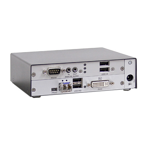
Units with 2-Card Chassis Transmitters Receivers Included Cards Included Cards i. 1 x Single-Link DVI-D with USB HID i. 1 x Single-Link DVI-D with USB HID Part Numbers Part Numbers i. CATx: OT2-SLDTXUD1D i. CATx: OR2-SRDTXUD1D ii. Fiber: OT2-SLDFSUD1D ii. Fiber: OR2-SRDFSUD1D Included Cards Included Cards i. -
Page 30: Figure 19. Units With 2-Card Chassis Part 2
Transmitters Receivers Included Cards Included Cards i. 1 x Single-Link DVI-D with USB HID i. 1 x Single-Link DVI-D with USB HID ii. USB 2.0 Only Embedded Upgrade Card ii. USB 2.0 Only Embedded Upgrade Card Part Numbers Part Numbers i. -
Page 31: Units With 4-Card Chassis
Units with 4-Card Chassis Transmitter: Part Numbers CATx: OT4-SLDTXUD1D/1T+1AS Fiber: OT4-SLDFSUD1D/1T+1AS Receiver: Part Numbers CATx: OR4-SRDTXUD1D/1T+1AS Fiber: OR4-SRDFSUD1D/1T+1AS Included Cards 1 x Single DVI-D with USB HID Analog Audio and Serial Embedded Upgrade Card iii. USB 2.0 Standalone Upgrade Card Transmitter: Part Numbers CATx: OT4-SLDTXUD1D/1T+1DA... -
Page 32: Figure 21. Units With 4-Card Chassis Part 2
Transmitter: Part Numbers CATx: OT4-SLDTXUD2D/1AS Fiber: OT4-SLDFSUD2D/1AS Receiver: Part Numbers CATx: OR4-SRDTXUD2D/1AS Fiber: OR4-SRDFSUD2D/1AS Included Cards 2x [1 x Single DVI-D with USB HID] Analog Audio and Serial Embedded Upgrade Card Transmitter: Part Numbers CATx: OT4-SLDTXUD2D/1DA Fiber: +OT4-SLDFSUD2D/1DA Receiver: Part Numbers CATx: OR4-SRDTXUD2D/1DA Fiber: OR4-SRDFSUD2D/1DA Included Cards... -
Page 33: Figure 22. Units With 4-Card Chassis Part 3
Transmitter: Part Numbers CATx: OT4-SLDTXUD2D/1E Fiber: OT4-SLDFSUD2D/1E Receiver: Part Numbers CATx: OR4-SRDTXUD2D/1E Fiber: OR4-SRDFSUD2D/1E Included Cards 2x [1 x Single DVI-D with USB HID] USB 2.0 Only Embedded Upgrade Card Transmitter: Part Numbers CATx: OT4-SLDTXUD2D/1E+1AS Fiber: +OT4-SLDFSUD2D/1E+1AS Receiver: Part Numbers CATx: OR4-SRDTXUD2D/1E+1AS Fiber: OR4-SRDFSUD2D/1E+1AS Included Cards... -
Page 34: Figure 23. Units With 4-Card Chassis Part 4
Transmitter: Part Numbers CATx: OT4-SLDTXUD2D/1E+1DA Fiber: OT4-SLDFSUD2D/1E+1DA Receiver: Part Numbers CATx: OR4-SRDTXUD2D/1E+1DA Fiber: OR4-SRDFSUD2D/1E+1DA Included Cards 2x [1 x Single DVI-D with USB HID] USB 2.0 with Digital Audio Embedded Upgrade Card Transmitter: Part Numbers CATx: OT4-SLDTXUD2D/1E+1AS Fiber: +OT4-SLDFSUD2D/1E+1AS Receiver: Part Numbers CATx: OR4-SRDTXUD2D/1E+1AS Fiber: OR4-SRDFSUD2D/1E+1AS... -
Page 35: Figure 24. Units With 4-Card Chassis Part 5
Transmitter: Part Numbers CATx: OT4-SLDTXUD2D/1T+1AS Fiber: OT4-SLDFSUD2D/1T+1AS Receiver: Part Numbers CATx: OR4-SRDTXUD2D/1T+1AS Fiber: OR4-SRDFSUD2D/1T+1AS Included Cards 2x [1 x Single DVI-D with USB HID] USB 2.0 Standalone Upgrade Card iii. Analog Audio and Serial Embedded Upgrade Card Transmitter: Part Numbers CATx: OT4-SLDTXUD2D/1T+1DA Fiber: OT4-SLDFSUD2D/1T+1DA Receiver:... -
Page 36: Figure 25. Units With 4-Card Chassis Part 6
Transmitter: Part Numbers CATx: OT4-SLDTXUD4D Fiber: OT4-SLDFSUD4D Receiver: Part Numbers CATx: OR4-SRDTXUD4D Fiber: OR4-SRDFSUD4D Included Cards 4x [1 x Single DVI-D with USB HID] Figure 25. Units with 4-Card Chassis Part 6 Orion Extender Installation and Operation Manual... -
Page 37: Units With 6-Card Chassis
Units with 6-Card Chassis Transmitter: Part Numbers CATx: OT6-SLDTXUD4D/1AS Fiber: OT6-SLDFSUD4D/1AS Receiver: Part Numbers CATx: OR6-SRDTXUD4D/1AS Fiber: OR6-SRDFSUD4D/1AS Included Cards 4 x [1 x Single DVI-D with USB HID] Analog Audio and Serial Embedded Upgrade Card Transmitter: Part Numbers CATx: OT6-SLDTXUD4D/1DA Fiber: OT6-SLDFSUD4D/1DA Receiver: Part Numbers... -
Page 38: Figure 27. Units With 6-Card Chassis Part 2
Transmitter: Part Numbers CATx: OT6-SLDTXUD4D/1E Fiber: OT6-SLDFSUD4D/1E Receiver: Part Numbers CATx: OR6-SRDTXUD4D/1E Fiber: OR6-SRDFSUD4D/1E Included Cards 4 x [1 x Single DVI-D with USB HID] USB 2.0 Only Embedded Upgrade Card Transmitter: Part Numbers CATx: OT6-SLDTXUD4D/1E+1AS Fiber: OT6-SLDFSUD4D/1E+1AS Receiver: Part Numbers CATx: OR6-SRDTXUD4D/1E+1AS Fiber: OR6-SRDFSUD4D/1E+1AS Included Cards... -
Page 39: Figure 28. Units With 6-Card Chassis Part 3
Transmitter: Part Numbers CATx: OT6-SLDTXUD4D/1E+1DA Fiber: OT6-SLDFSUD4D/1E+1DA Receiver: Part Numbers CATx: OR6-SRDTXUD4D/1E+1DA Fiber: OR6-SRDFSUD4D/1E+1DA Included Cards 4 x [1 x Single DVI-D with USB HID] USB 2.0 with Digital Audio Embedded Upgrade Card Transmitter: Part Numbers CATx: OT6-SLDTXUD4D/1T Fiber: OT6-SLDFSUD4D/1T Receiver: Part Numbers CATx: OR6-SRDTXUD4D/1T... -
Page 40: Figure 29. Units With 6-Card Chassis Part 4
Transmitter: Part Numbers CATx: OT6-SLDTXUD4D/1E+1AS Fiber: OT6-SLDFSUD4D/1E+1AS Receiver: Part Numbers CATx: OR6-SRDTXUD4D/1E+1AS Fiber: OR6-SRDFSUD4D/1E+1AS Included Cards 4 x [1 x Single DVI-D with USB HID] Analog Audio and Serial Embedded Upgrade Card iii. USB 2.0 Standalone Upgrade Card Transmitter: Part Numbers CATx: OT6-SLDTXUD4D/1T+1DA Fiber: OT6-SLDFSUD4D/1T+1DA Receiver:... -
Page 41: Installation
INSTALLATION Installation It is recommended that first-time users initially set up the Orion Xtender system in a single room as a test setup. Doing so allows for identification and resolution of any cabling problems, and provides a more convenient way to experiment with the system. -
Page 42: Setup Of Upgrade Modules
Setup of Upgrade Modules The modules can be hot plugged. Upgrade Module Analog Audio / Serial: 1. Connect the audio source to the Transmitter unit (e.g. CPU audio output with Transmitter audio input, CPU audio input with Transmitter audio output). 2. -
Page 43: Status Leds
INDICATORS Status LEDs The Orion Xtender cards shown in the previous section are equipped with Status LEDs. These indicators provide a visual output of working and fault conditions. This section describes the various indicators and the conditions they represent. Video Cards The Status LEDs on the Single-Link DVI-D, Dual-Link DVI-D, DVI-I (VGA) and HDMI video cards are described here. -
Page 44: Figure 31. Status Leds On Hdmi Video Cards
Transmitters Receivers HDMI Figure 31. Status LEDs on HDMI Video Cards LED # LED Type Status Description Connection available Failure LED (Green) Connection failure (flashing for about 20 s following a On or Flashing connection failure) Flashing No connection via interconnect cable Status LED (Green) Connection available Table 2. -
Page 45: Embedded Upgrade Cards
Figure 32. Font Panel LED on DVI-I (VGA) Video Card LED Color Description Dark Red No video signal; monitor not detected Video signal not supported; monitor not detected Green Video signal supported; monitor not detected Blue No video signal; monitor detected Violet Video signal not supported;... -
Page 46: Usb-Hid Only Embedded Upgrade Card
USB-HID Only Embedded Upgrade Card Transmitter Receiver Figure 34. Status LEDs on USB-HID Only Embedded Upgrade Card LED # Type Status Description No USB-HID device or no supported USB device connected Device LED Flashing fast USB-HID device active (orange) USB-HID device ready or KVM Extender in command mode No power supply voltage Transmitter: KVM Extender in command mode or no connection... -
Page 47: Usb 2.0 Only Embedded Upgrade Card
USB 2.0 Only Embedded Upgrade Card Transmitter Receiver Figure 35. Status LEDs on USB-2.0 Only Embedded Upgrade Card LED # Type Status Description No USB 2.0 device connected Status LED (green) Flashing slowly USB 2.0 device connected No connection to source (computer,CPU) available Connection to source (computer, CPU) available Status LED Flashing slowly... -
Page 48: Standalone Upgrade Cards
Standalone Upgrade Cards The Status LEDs on the Standalone USB 2.0 Upgrade Card are described here. A new generation of the card is now available, and the Status LEDs indicate different conditions from the first generation cards. Both generations of the USB 2.0 Standalone Upgrade Card are described here. The card has a multi-color LED on both the front and rear panels for overall status indication. -
Page 49: Second Generation Usb 2.0 Standalone Upgrade Card
Second Generation USB 2.0 Standalone Upgrade Card Transmitter Receiver Figure 37. Status LEDs on Second Generation USB 2.0 Standalone Upgrade Card LED # Type Status Description Connection available Failure LED Connection failure (flashing for about 20 s following a (green) On or Flashing connection failure) No connection via interconnect cable... -
Page 50: Operation
OPERATION Operation Operation of the Orion Xtender is very simple and straightforward. In most instances, once installed, no further configuration is needed. Certain functions are available for further customization, if desired. These functions are described in this section. The files needed to configure the Orion Xtender units reside in the data area of the units. To access this area, connect the service port of the Transmitter or Receiver unit to a computer using a USB mini cable. -
Page 51: Ddc Settings
The 'Hot Key' sequence to enter Command Mode can be changed. The following table lists the 'Hot Key' Codes for the available key choices. 'Hot Key' Code 'Hot Key' Hot Key can be selected by user 2x <Scroll> 2x <Left Shift> 2x <Left Ctrl>... -
Page 52: Working With The Ddc Information File
Working with the DDC Information File The DDC information file, “DDC-EDID.bin”, can be found on the “Extender” flash drive, as described at the beginning of this section. Retrieving DDC Information Copy the "DDC-EDID.bin" file from the flash drive of the Transmitter unit to the computer. To open the binary file, a suitable software program, e.g. -
Page 53: Configuration File
Configuration File The Transmitter and Receiver contain a configuration file, “Config.txt”, to set specific parameters and to read out device and video information. It can be found on the “Extender” flash drive, as described at the beginning of this section. The configuration file can be edited with all common text editors. -
Page 54: Transmitter Settings
Transmitter Settings The following settings can be written to the configuration file of a Transmitter. Setting Function DDC Management LOCKEDID Activate DDC write protection Digital Audio (only with digital audio upgrade module) SRC32000 Activate sample rate conversion, sample rate 32 kHz SRC44100 Activate sample rate conversion, sample rate 44,1 kHz SRC48000... -
Page 55: Transmitter And Receiver Settings
Transmitter AND Receiver Settings The following settings must be written to the configuration files of both Transmitter and Receiver. Setting Function Local switching (only with HDMI extenders and local control by an USB-HID Receiver upgrade module) BLANKSCR Activate dark switching between local and remote console by keyboard or mouse event Activate switching of video and control between local and remote console by keyboard PRIVATEMODE commands... -
Page 56: Troubleshooting The Orion Xtender System
If the Orion Xtender system does not function as expected, there are a few simple checks that can be made to determine the cause of the failure. This sections details the steps the user can take to resolve the problem. Should the difficulties persist, contact Rose Electronics Customer Support. General Failures... -
Page 57: Video Card Usb Hid Failure
Violet cycle power to it. Re-plug video cable to CPU. USB device does not USB HID device is not supported Contact Rose Electronics if necessary function Table 22. Troubleshooting Video Card USB HID Failure Serial Connection Failure Symptom Diagnosis... -
Page 58: Digital Audio Failure
Device at higher / lower USB HID HID device LED 1 / 2 off port not detected Connect USB HID device Contact Rose Electronics, if necessary Connection between Transmitter Transmitter: LED 3 off Check interconnect cables and connectors and Receiver... -
Page 59: Usb 2.0 Only Embedded Upgrade Card Failure
USB 2.0 device is not supported New connection of the USB 2.0 device function Contact Rose Electronics, if necessary Table 27.Troubleshooting USB 2.0 Only Embedded Upgrade Card Failure First Generation USB 2.0 Standalone Upgrade Card Failure The steps to troubleshoot this failure utilize the Status LEDs on the First Generation USB 2.0 Standalone... -
Page 60: Safety
SAFETY Safety The Orion Xtender system, like all electronic equipment, should be used with care. To protect yourself from possible injury and to minimize the risk of damage to the Unit, read and follow these safety instructions. Follow all instructions and warnings marked on this Unit. Except where explained in this manual, do not attempt to service this Unit yourself. -
Page 61: Maintenance And Repair
This Unit does not contain any internal user-serviceable parts. In the event a Unit needs repair or maintenance, you must first obtain a Return Authorization (RA) number from Rose Electronics or an authorized repair center. This Return Authorization number must appear on the outside of the shipping container. -
Page 62: Table 29. Hdmi Audio Specifications
APPENDICES Appendix A – General Specifications This section gives the general specifications for the Orion Xtender connectors, pinouts, cables and dimensions. Interfaces The different types of possible connections, and any restrictions on them, are discussed here. DVI-D Single Link The video interface supports the DVI-D protocol. All signals that comply with the DVI-D Single Link specifications can be transmitted. -
Page 63: Usb-Hid
Orion Xtender models with fiber interconnects operate through Gigabit SFPs, which have to be connected with suitable fibers fitted with LC-type connectors. Correct function of the extenders can only be guaranteed when the SFPs provided by Rose Electronics are used. Note: SFP modules can be damaged by electrostatic discharge (ESD). -
Page 64: Table 30. Serial Interface Specifications
Serial Interface The serial interface option supports full-duplex transmission with a real hardware handshake up to a Baud rate of 115,200 Baud. The Receiver is wired as DTE (Data Terminal Equipment, like CPU output) and can be connected directly to DCE devices (Data Communication Equipment). Serial touch screens can be connected directly to the Receiver unit. -
Page 65: Table 32. Analog Audio Specifications
Analog Audio Interface The analog audio option supports bidirectional stereo audio transmission, at near CD quality. The audio interface is a 'line level' interface and it is designed to transmit the signals of a sound card (or other 'line level' device), as well as to allow the connection of active speakers to the Receiver unit. -
Page 66: Table 34. Digital Audio Specifications
Digital Audio Interface The digital audio option supports the unidirectional transmission of digital audio data. Up to three sources can be connected to the Transmitter unit. The active source is transmitted. If several sources are active simultaneously, the XLR signal takes priority; otherwise, the first active signal does. All three connectors on the Receiver concurrently provide digital audio. -
Page 67: Table 35.Catx Cable Specifications
Interconnect Cable The cables used to connect the Orion Xtender Transmitter and Receiver units are to each other, and to the Orion X and Orion XC matrix switches are described here. CATx A point-to-point connection is required. Operation with several patch fields is possible. Routing over an active network component, such as an Ethernet Hub, Router or Matrix, is not allowed. -
Page 68: Table 37, Fiber Cable Specifications
Fiber A point-to-point connection is necessary. Operation with multiple patch panels is allowed. Routing over active network components, such as Ethernet Hubs, Matrixes or Routers, is not allowed. Type of Interconnect Cable (Cable notations according to VDE) Type of Cable Specifications Two fibers 9μm I-V(ZN)H 2E9 (in-house patch cable) -
Page 69: Figure 39. Dvi-D And Dvi-I Single-Link Connector Pinouts
Orion Xtender models featuring a transparent USB 2.0 connection use a proprietary technology which supports most types of USB 2.0 and USB 1.1 devices. However, the manufacturer cannot guarantee compatibility with every device on the market. Please contact Rose Electronics if any issues are found. Connector Pinouts This section shows the pinouts for the connectors on the Orion Xtender cards. -
Page 70: Figure 40. Dms-59 Dual-Link Connector Pinouts
DVI-I Single-Link Connector Pinouts Pin Signal Signal Pin Signal T.M.D.S data 2- T.M.D.S data 1- T.M.D.S data 0- T.M.D.S data 2+ T.M.D.S data 1+ T.M.D.S data 0+ T.M.D.S data 2 GND T.M.D.S data 1 GND T.M.D.S data 0 GND n.c. n.c. -
Page 71: Figure 41, Hdmi Connector Pinouts
HDMI Connector Figure 41, HDMI Connector Pinouts Pin Signal Signal Signal T.M.D.S data 2 + T.M.D.S data 0 GND DDC Input (SCL) T.M.D.S data 2 GND T.M.D.S data 0 - DDC Output (SDA) T.M.D.S data 2 - T.M.D.S clock + DDC/CEC/HEC GND T.M.D.S data 1 + T.M.D.S clock GND... -
Page 72: Figure 44. Mini Usb Type B Connector
Mini USB Type B Connector Figure 44. Mini USB Type B Connector Pin Signal Color Pin Signal Color VCC (+5VDC) n.c. – Data – White Black Data + Green Table 45. Mini USB Type B Connector Pinouts PS/2 Connector Figure 45. PS/2 Connector Pinouts Pin Signal Pin Signal Pin Signal... -
Page 73: Figure 48. Power Supply Connector Pinouts
Power Supply Connector Power Supply Connector Figure 48. Power Supply Connector Pinouts Signal Signal Inside VCC (+5VDC) Outside GND Table 49, Power Supply Connector Pinouts Serial Connectors D-Sub 9 (Serial) Connector for RS232 and RS422 Figure 49. D-Sub 9 (Serial) RS232 and RS422 Connector Pinouts D-Sub 9 (Serial) RS232 Connector Pinouts Pin Signal Pin Signal... -
Page 74: Figure 50. 3.5 / 6.35 Mm Stereo Jack Plug Pinouts
Analog and Digital Audio Connectors 3.5 / 6.35 mm Stereo Jack Plug Figure 50. 3.5 / 6.35 mm Stereo Jack Plug Pinouts Pin Signal Pin Signal Pin Signal Audio IN / OUT L Audio IN / OUT R Table 53. 3.5 / 6.35 mm Stereo Jack Plug Pinouts RCA (Cinch) Connector Figure 51. -
Page 75: Table 57.Orion Xtender Chassis Part Numbers
Appendix B – Part Numbers Part Numbers for the Orion Xtender Chassis models are given here. The Part Numbers for Orion Xtender Cards can be found in the section Orion XTender Card Types found on page 12. Chassis Part Number Description 1OEE_CH02 Chassis for up to 2 boards, 1x external power supply unit... -
Page 76: Table 60. Orion Xtender Power Requirements
Power Requirements Per Unit Orion Xtender Units Single-Head devices max. 0.8 Amp Onboard DVI-I devices max. 1.2 Amp max. 1.7 Amp Redundancy devices max. 1.05 Amp Orion Xtender Cards Analog Audio / Serial max. 0.3 Amp Serial(RS422) max. 0.15 Amp Balanced Audio max 0.5 Amp Digital Audio... -
Page 77: Table 62. Orion Xtender Chassis Physical Dimensions
Appendix E – Physical Specifications The physical dimensions and weights of the Orion Xtender Chassis models are described here. Physical Dimensions Chassis Model Extender Unit Size Shipping Box Size 5.7 in x 5.8 in x 1.7 in / 8.3 in x 5.5 in x 6.5 in / 1OEE_CH02 145 mm x 147 mm x 41 mm 210 mm x 140 mm x 165 mm... - Page 79 ▪ ▪ WWW.ROSE.COM sales@rose.com (800) 333-9343 ▪ ▪ Rose Electronics 10707 Stancliff Road Houston, Texas 77099 Rose USA (281) 933-7673 ▪ Rose Europe +49 (0) 2454 969442 Rose Asia +65 6324 2322 ▪ Rose Australia +61 (0) 421 247083 WWW.ROSE.COM...
Need help?
Do you have a question about the Orion XTender OT2-SLDTXUD1D and is the answer not in the manual?
Questions and answers