
Subscribe to Our Youtube Channel
Related Manuals for Rose electronics Xcion XCK-2DTXUD1D


Summary of Contents for Rose electronics Xcion XCK-2DTXUD1D
- Page 1 Xcion Extender DVI / VGA / HDMI Switchable KVM Extender over CATx or Fiber Switching Options Installation and Operation Manual 10707 Stancliff Road Phone: (281) 933-7673 Houston, Texas 77099 tech-support@rose.com...
- Page 2 Xcion Switch Mode Extender to be in good working order for one year from the date of purchase from Rose Electronics or an authorized dealer. Should this product fail to be in good working order at any time during this one-year warranty period, Rose Electronics will, at its option, repair or replace the Unit as set forth below.
- Page 3 DECLARATIONS OF CONFORMITY This is to certify that, when installed and used according to the instructions in this manual, together with the specified cables, the Units listed in are shielded against the generation of radio interferences in PPENDIX accordance with the application of Council Directives 2006/95/EC and 2004/108/EC, as well as these standards: ■...
-
Page 4: Table Of Contents
TABLE OF CONTENTS Contents Disclaimer System Introduction Features Package Contents Xcion Models Front View All Models Rear View DVI CATx and Fiber Models Connector Description DVI Models HDMI CATx Model Connector Description HDMI Model Installation Start Up Status Overview Xcion Menu System Update Flash Firmware Option Overview DDC Options... - Page 5 Figure 4. Connectors on DVI Transmitter Figure 5. Connectors on DVI Receiver Figure 6. Xcion HDMI Rear View Figure 7. Connectors on HDMI Transmitter Figure 8. Connectors on HDMI Receiver Figure 9. Xcion DVI Switch Mode Installation Figure 10. Xcion HDMI Switch Mode Installation Figure 11.
- Page 6 Table 3. Front Panel Status Indicators Table 4. RS232 RJ12 Pinouts Table 5. RS232 Transmission Rates Table 6. Firmware Update Terminology Table 7. Troubleshooting the Xcion Extenders Table 8. Xcion Extender Specifications Table 9. CATx Cable Pins Appendices Appendix A – Specifications Appendix B –...
-
Page 7: Disclaimer
(See limited warranty.) System Introduction Thank you for choosing the Xcion Switch Mode family of extenders. They are the result of Rose Electronics commitment to providing state-of-the-art solutions for today’s demanding workplace. The Xcion Switch Mode Extender is the ideal device for extending HDMI, DVI or VGA video and USB with no loss of video quality. -
Page 8: Features
Features ■ Extends full HD 1080p and 1920 x 1200 @ 60 Hz digital or analog video with no loss of quality ■ Transparently extends USB 1.1 and 2.0 devices at speeds up to 12Mbps ■ Extensions distances up to 492 ft (150 m) over CATx or 1640 ft (500 m) over multi-mode fiber ■... -
Page 9: Xcion Models
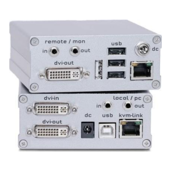
MODELS Xcion Models The Xcion is available in three distinct models as described below. Front View All Models Figure 1. Xcion Extenders Transmitter and Receiver Front View Rear View DVI CATx and Fiber Models Figure 2. Xcion DVI CATx Receiver and Transmitter Rear View Figure 3. -
Page 10: Connector Description Dvi Models
Connector Description DVI Models 1. dvi-in: Use the supplied DVI cable to connect this port to the DVI port on the source computer. 2. dvi-out: Connect a DVI monitor to this port for a local display, if desired. 3. usb: Use the supplied USB cable to connect to a USB port on the source computer. -
Page 11: Hdmi Catx Model
HDMI CATx Model Figure 6. Xcion HDMI Rear View Connector Description HDMI Model 1. PC In: Use the supplied HDMI cable to connect this port to the HDMI port on the source PC. 2. Monitor Out: Connect an HDMI monitor to this port for a local display, if desired. -
Page 12: Installation
INSTALLATION Installation Easy installation allows the Xcion Switch Mode to be set up as a KVM matrix quickly. Connect the Transmitter to the host computer using the supplied video cable (DVI or HDMI) and the USB cable. Connect a display to the local video output port, if desired. -
Page 13: Figure 10. Xcion Hdmi Switch Mode Installation
An individual HDMI Transmitter and Receiver setup is shown the figure below. Figure 10. Xcion HDMI Switch Mode Installation Connect all the computers, monitors, USB and Sound devices in this manner to the Transmitters and Receivers that are intended to be part of the KVM matrix. Then, connect the Transmitters and Receivers to the Ethernet switch. -
Page 14: Start Up
It is important to note that the entire switching network system requires its own dedicated network. For security reasons it cannot be integrated into an existing company network. The network switch must be a 1 Gigabit Switch, with true port to port transfer rates of 1 Gigabit/second. A listing of Gigabit Network Switches that have been tested with the Xcion Switch Mode Extender system can be found in PPENDIX... -
Page 15: Xcion Menu System
Press the U key on the keyboard to initiate the upgrade of the flash firmware on the Transmitter and Receiver. The latest version of the flash firmware can be obtained from Rose Electronics. All update files are accompanied by a detailed description of the update process to assist in performing this operation. -
Page 16: Option Overview
Figure 14. Xcion DVI and HDMI Options Overview Menu The Menu displays the Device ID of the extender. To purchase an option, please contact Rose Electronics or your distributor with the Device ID number, as well as the Serial Number located on the side of the device. If the option has been purchased, the activation code for the desired option will be sent. -
Page 17: Network Settings
Network Settings Press the W key on the keyboard to bring up the Network Settings Menu. The menu includes the preferences and settings for the switching option. It is described in detail in the SWITCHING M UIDE ETTINGS section found on page 17. Extender Settings Press the G key on the keyboard to display the Extender Settings menu. -
Page 18: Local Extender Settings
The Remote Extender Settings are accessed by pressing the R key on the keyboard. Figure 18. Remote Extender Settings Screen Local Extender Settings This section describes the available Local Extender Settings. VGA Parameters (DVI Model Only) Press the V key on the keyboard to modify VGA settings. Figure 19. -
Page 19: Remote Extender Settings
The available settings are given below. Press the appropriate key on the keyboard to access them. ■ Press F1 to move the video up or F4 to move the video down. ■ Press F2 to move the video left or F3 to move the video right. ■... -
Page 20: Figure 21. Rs232 Rj12 Port
RS232 Settings (DVI Model Only) The following signals are transferred; the pin numbers refer to the RJ12 com connector. The remote interfaces are DTE. Figure 21. RS232 RJ12 Port Signal Name Abbrev. Direction Description Data Set Ready Input Reserved (not used) Data Terminal Ready Output Pulled high with 1 kΩ... -
Page 21: Figure 22. Extender Settings / Lock Menu Submenu
Monitor Synchronization Press the key on the keyboard to enable or disable monitor synchronization. When enabled, the refresh rate of the graphics card on the source computer and the remote monitor are adjusted to match one another. This ensures smooth video transmission when the screen content changes rapidly, as when playing a video. Not all monitors can support this function, so this option is disabled by default. -
Page 22: Switching List
Menu Item “H” – Keyboard Shortcuts Press the H key on the keyboard to open the KEYBOARD SHORTCUTS screen. In this menu alternative keyboard shortcuts can be defined. Figure 23. Keyboard Shortcuts Screen By default, only one shortcut can be modified - the one to open the OSD. It should be noted that if new shortcut is assigned for opening the OSD, the 5xScroll Lock will still continue to function. -
Page 23: Switching Menu Guide / Settings
SWITCHING Menu Guide / Settings The Switching Option settings can be accessed by pressing “W” in the main menu of the OSD where the network can be configured. Please note that this menu item is only active when the Switching Option has been unlocked on the Receiver. -
Page 24: Master View (Device Configuration) Menu
Master View (Device Configuration) Menu Press the V key in the Network Settings menu to display the Master View Menu. This menu provides the administrator with the ability to view, add, edit or remove user, console and computer information. Figure 26. Network Settings / Master View Menu Master View / Connections Overview Press the O key on the keyboard to display the Connections Overview screen. -
Page 25: Figure 28. Master View / Connections Detail Screen
To view more details of a connection, use the arrow keys on the keyboard to select one of the connections and press the key. This brings up the Master View Connections Detail Submenu where more information about the connection can be viewed. Figure 28. -
Page 26: Figure 30. Master View / User Detail Screen
Figure 30. Master View / User Detail Screen The following user characteristics may be edited in this screen. User Assign each user a login name with maximum length of 16 characters. Full Name The full name of a user may be entered for clarity. This name is displayed when informing other users who interrupted their connection. -
Page 27: Figure 31. Master View / Console Extender List Screen
Master View / Console Extender List Press the C key on the keyboard to display the Console Extender List screen. Here, all console extenders (Receivers) in the switching network, and their current status can be viewed. Figure 31. Master View / Console Extender List Screen The Console Extenders can be in one of the following statuses: ■... -
Page 28: Figure 33. Master View / Multi-Head Configuration Screen
Master View / Multi-Head Configuration If multiple monitors are used with a PC, then individual local and remote extenders can be grouped together using Multi-Head settings. This allows them to be switched as a single unit. To aid in identification of the extenders, it is recommended that every extender is first named through the PC Extender List and Console Extender List screens described above. -
Page 29: Network Mode
In the Multi-Head Configuration screen, an existing multi-head set can be viewed and edited by selecting it and pressing the key. A dismantled or altered Multi-Head set can be removed from the system by selecting it in the menu and pressing the R key. Network Mode Network modes are used to define how the network system is to operate. - Page 30 Network Modes / Private Connections Press the V key to enable or disable Private Connections in the system. When Private Connection is enabled, users can set up a private connection with a computer, which can’t be interrupted by other users. To establish a private connection, hold down the Shift key when selecting a new connection either through the switching menu or by pressing the hotkey combination shown in .
-
Page 31: Set Timeout
Set Timeout When Passwords are enabled, the Set Timeout facility defines the conditions under which a user will be required to enter their login credentials when switching. This facility is invoked in the Password Timeout screen, accessed by pressing the T key. Figure 36. -
Page 32: Switching Between Computers
Switching Between Computers The menu for the switching option is accessed from a USB keyboard on the Receiver. Press Ctrl+Alt+F12 to display the switching screen, or display the Main Menu and press the L key. An example of a switching screen is shown below. -
Page 33: Video Sharing
Video Sharing With Firmware version 4245 and later, when Video Sharing mode is enabled, users can share their screen or view the screen of another user on the network. Control over the Transmitter depends on whether the Transmitter has an active connection to a Receiver or not. Video Sharing can occur in two ways as described below. -
Page 34: Firmware Update Instructions
Firmware Update Instructions Firmware update on the Xcion Switch Mode Extender can be performed in one of three ways as follows. ■ Direct Update ■ Automatic Update ■ Network Update. These methods are available in the UPDATE screen, which is accessed from the main menu (Figure 13) by pressing the U key on the keyboard. -
Page 35: Direct Update
Direct Update Direct Update was previously the only method of updating the Xcion extenders. It is designed to update a pair of extenders (one Transmitter and one Receiver). The update is initiated on the Receiver. Direct update is accomplished by following the steps outlined below. 1. -
Page 36: Figure 39. Automatic Update Settings Screen
Automatic Update is a feature that is disabled by default. It can be enabled or disabled for the Receiver or Transmitter from the Automatic Update screen. It is highly recommended that a Receiver is used as the Source Extender. Figure 39. Automatic Update Settings Screen Important: If the Source Extender does not have a Saved Firmware, then Automatic Update cannot be performed. -
Page 37: Figure 41. Commencing Of Automatic Update
5. After about 30 seconds the OSD on the monitor will indicate that the Automatic Update process has begun, as shown in the figure below. The LED on the Target Extender will now blink very slowly green. Figure 41. Commencing of Automatic Update 6. -
Page 38: Network Update
Network Update This is the preferred method of updating extenders on a switching network. A new update may be distributed to the extenders on the network with minimal impact on the network. Here, the Source Extender can load a firmware update from a bitmap, then transfer the update to any or all extenders on the network, and tell those extenders to update to the new firmware. -
Page 39: Figure 44. Load New Version From Bitmap Screen
Load New Version from Bitmap This operation will transfer firmware from a bitmap file to the Saved Firmware of the Receiver on which the user is working (marked in green). For this to work, the bitmap must be open and visible on the monitor. ■... -
Page 40: Troubleshooting
Ensure that the interconnect cable (CATx or Fiber) Transmitter and Receiver is connected securely on both ends. A clicking noise should be heard when plugging in the cable. Contact Rose Electronics if the problem still occurs. LED lights up orange No video Ensure that the local (PC) cable is connected securely. -
Page 41: Safety
SAFETY Safety The Xcion extender system, like all electronic equipment, should be used with care. To protect yourself from possible injury and to minimize the risk of damage to the Unit, read and follow these safety instructions. Follow all instructions and warnings marked on this Unit. ... -
Page 42: Maintenance And Repair
This Unit does not contain any internal user-serviceable parts. In the event a Unit needs repair or maintenance, you must first obtain a Return Authorization (RA) number from Rose Electronics or an authorized repair center. This Return Authorization number must appear on the outside of the shipping container. -
Page 43: Table 8. Xcion Extender Specifications
APPENDICES Appendix A – Specifications Physical Specifications (All Models) Dimension (W x D x H) 3.88 in x 4.17 in x 1.6 in / 98 mm x 106 mm x 41 mm Rackmount Up to 4 Transmitters or Receivers in a 19” 1U rack Weight 1.19 lb (540 g) Video... -
Page 44: Appendix B - Part Numbers
Appendix B – Part Numbers Product Part Number Xcion, DVI/USB Extender Kit, CATx XCK-2DTXUD1D Xcion, DVI/USB Extender Kit, Multi-mode Fiber XCK-2DFMUD1D Xcion, DVI/USB Extender Kit, Single-mode Fiber XCK-2DFSUD1D Xcion, HDMI/USB Extender Kit, CATx XCK-2DTXUH1H Audio/Serial Option USB 2.0 High Speed Option (64Mbps) VGA Input Option Switch Mode Option Appendix C –... -
Page 45: Table 9. Catx Cable Pins
Appendix F – Cable Specification CAT5/6/7 Cables The pins are connected 1:1. EIA/TIA-568 B Schema Color Orange / White Orange Green / White Blue Blue / White Green Brown / White Brown Table 9. CATx Cable Pins Notes: ■ The pins are connected to EIA/TIA-568A (rare) or EIA/TIA-568 B (common) pairs. Erroneous assignments cannot be found with a simple cable tester. -
Page 46: Appendix G - Appropriate Firmware Update Methods
Appendix G – Appropriate Firmware Update Methods This Appendix lists the different methods to upgrade firmware from a particular version to a later version. Firmware Update of Xcion DVI Switch Mode Extenders Starting Firmware Version 1100 – 1269 1273 4200+ Direct Update to new version Direct Update to new version Direct Update to new version... - Page 47 ▪ ▪ WWW.ROSE.COM sales@rose.com (800) 333-9343 ▪ ▪ Rose Electronics 10707 Stancliff Road Houston, Texas 77099 Rose USA (281) 933-7673 ▪ Rose Europe +49 (0) 2454 969442 ▪ Rose Asia +65 6324 2322 Rose Australia +61 (0) 421 247083 WWW.ROSE.COM...
Need help?
Do you have a question about the Xcion XCK-2DTXUD1D and is the answer not in the manual?
Questions and answers