Table of Contents
Troubleshooting

Subscribe to Our Youtube Channel
Related Manuals for Nilfisk-Advance SC6000 36C


Summary of Contents for Nilfisk-Advance SC6000 36C
- Page 1 SC6000 Service Manual Nilfisk Model Numbers: Advance Model Numbers: 56116000 SC6000 36C 56116003 SC6000 910C 56116001 SC6000 40D 56116004 SC6000 1050D 56116002 SC6000 34D 56116005 SC6000 860D Language June/2016 Form No. 56043174...
-
Page 2: Table Of Contents
Service Manual – SC6000 Contents Contents 03 - General Information . . . . . . . . . . . . . . . . . . . . . . . . . . . . . . . . . . . 7 General Machine Description Service Manual Purpose and Application Other Reference Manuals and Information Sources... - Page 3 Service Manual – SC6000 Contents Configuration Menu System Menu Impact Log Troubleshooting Guide Main Controller (E2) Error Codes Power Module (E3) Error Codes Specifications Sample Shop Voltage Measurements Main Control Board J1 Connector (Black) Main Control Board J2 Connector (Gray) Power Module J3 connector Power Module Heavy Current Lugs Motor Amp Draw measurements...
- Page 4 Service Manual – SC6000 Contents Setting Onboard Charger Battery Profile Removal and Installation Batteries Paddle Switches Floor Panel Steering Column Cover Specifications Connector Pinouts Main Control Board J1 Connector Main Control Board J2 Connector Power Module J3 Connector Drive Controller J4 Connector TrackClean X163 Connector Level Sensor X79 Connector Steering Column Paddle X98 Connector...
- Page 5 Service Manual – SC6000 Contents Deck Lift Actuator Getting Neutral Weight on the Deck Brush Motor Brush Motor Brushes Specifications Special Tools Actuator Test Kit 34 - Scrub System, Cylindrical . . . . . . . . . . . . . . . . . . . . . . . . . . . . . . 103 Functional Description Deck Lift Actuator Scrub Control...
- Page 6 Service Manual – SC6000 Contents 90 - Options and Accessories . . . . . . . . . . . . . . . . . . . . . . . . . . . . . . . 134 Dual Vacuum EcoFlex Side Sweep...
-
Page 7: 03 - General Information
Service Manual – SC6000 03 - General Information General Machine Description The SC6000 machine is a battery-powered, ride-on, self-propelled commercial floor scrubbing machine with either a disc or cylindrical scrub system, and suitable for use in commercial applications The machine is available with one of three deck types The 34D/860D has a 34"... -
Page 8: Conventions
Service Manual – SC6000 03 - General Information Conventions All references to right, left, front and rear in this manual are as seen from the Operator’s position Modifications Modifications and additions to the cleaning machine which affect capacity and safe operation shall not be performed by the owner or user without prior written approval from Nilfisk Inc. -
Page 9: Safety
Service Manual – SC6000 03 - General Information Safety Symbols It is important for you to read and understand this manual The information it contains relates to protecting your safety and preventing problems The symbols below are used to help you recognize this information DANGER: Indicates a potentially hazardous situation which, if not avoided, will result in death or serious injury. - Page 10 Service Manual – SC6000 03 - General Information Property Damage Messages − Storage and operation temperature must be above 0°C and a humidity between 30% and 95%, non-condensing. − Before use, all doors and hoods should be properly latched. − This machine is not approved for use on public paths or roads. −...
-
Page 11: Lifting Or Transporting The Machine
Service Manual – SC6000 03 - General Information Lifting or Transporting the Machine CAUTION: Never work under a machine without safety stands or blocks to support the machine. − Drain the recovery and solution tanks to prevent sloshing water from unbalancing the machine. -
Page 12: Technical Specifications
Service Manual – SC6000 03 - General Information Technical Specifications Model 36C/910C 34D/860D 40D/1050D Model No. 56116000 / 56116002 / 56116001 / 56116003 56116005 56116004 Voltage, Batteries V Battery Capacity (max) Ah Protection Grade, Operating Class 3 Protection Grade, Charging Class 1 Sound Pressure Level IEC 60335-2-72: 2002 Amend. -
Page 13: Fastener Torque Specifications
Service Manual – SC6000 03 - General Information Fastener Torque Specifications Size Plated Steel Stainless Steel 42 in.-lb. 28 in.-lb. 1/4“ 100 in.-lb. 67 in.-lb. 5/16” 17 ft.-lb. 11 ft.-lb. 3/8” 31 ft.-lb. 20 ft.-lb. Standard Torque 1/2” 75 ft.-lb. 50 ft.-lb. -
Page 14: Lubricating The Machine
Service Manual – SC6000 03 - General Information Lubricating the Machine • Once a month, apply light machine oil to lubricate the components marked by (B) below: • Once per quarter Grease the components marked by (A) below... -
Page 15: Know Your Machine
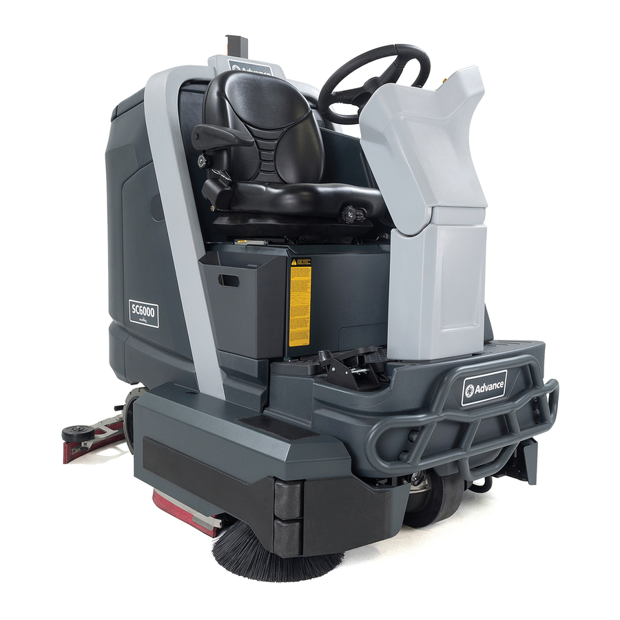
Service Manual – SC6000 03 - General Information Know Your Machine Solution Tank Steering Column Recovery Tank Side Doors Squeegee Chassis Scrub Deck Side Broom... -
Page 16: 04 - Control System
Service Manual – SC6000 04 - Control System Functional Description Within the SC6000 system there are three primary controllers: the Main Machine Controller (E2), the Power Module (E3), and the Wheel Drive controller (E4) The three modules communicate with one another via a CAN Bus (Controller Area Network) This permits each of the modules to perform their separate functions, while still functioning as a complete system (There is also a second, separate CAN Bus between the Main Machine Controller and the optional TrackClean Module ) -
Page 17: Wheel Drive Controller
Service Manual – SC6000 04 - Control System Wheel Drive Controller The wheel drive controller operates and monitors the wheel motor It generates a 3-phase Pulse Width Modulated (PWM) power control to the wheel motor Even though it is actually DC power, it resembles a 3-phase system because the polarity reversals and zero-crossings resemble a 3-phase AC system This pseudo 3-phase power permits the wheel motor to achieve full torque at near zero rpm, and very precise position control... -
Page 18: Power Module
Service Manual – SC6000 04 - Control System Power Module As the name suggests, the power module handles the high-power output functions for the machine It receives its commands from the main machine controller via the CAN Bus network The power module provides basic motor control and protection, but the main machine controller controls the actual operation commands for the motors The power module receives its logic power from the KSI relay, which is controlled by the main machine... -
Page 19: Main Machine Controller
Service Manual – SC6000 04 - Control System Main Machine Controller As the name implies, the Main Machine Controller (MMC) is the primary controller for the system The MMC functions as the primary interface for the operator, and directly or indirectly controls the functions of the machine Because the MMC controls the on/off function of the whole machine, it is always receiving logic power through the 10 amp circuit breaker, but controls the status of the KSI relay to itself and the other controllers... -
Page 20: Main Controller Operational Modes
Service Manual – SC6000 04 - Control System Main Controller Operational Modes The main controller is firmware driven using a micro controller to set operational modes based on machine input and function These modes of operation are described below • Normal Modes –... - Page 21 Service Manual – SC6000 04 - Control System – Vac motors M4 and M5 – Wand mode (seat switch open upon entry) or Squeegee Actuator M6 ◦ No recovery system fault (vac motors and squeegee) ◦ No Estop inhibit ◦ No impact lockout inhibit ◦...
- Page 22 Service Manual – SC6000 04 - Control System • Other Main Controller outputs – Dust Guard Solenoid L2 – See above (same as dust guard pump) – Horn H1 ◦ Always active Follows S3 horn switch input – Back up alarm H2 ◦...
-
Page 23: Control Panel
Service Manual – SC6000 04 - Control System Control Panel The control panel (display) is an integral component with the Main Machine Controller circuit board The control panel contains an LCD display, SmartKey reader for the keyswitch, and a series of membrane switches for operator control SmartKey Reader (A): The key reader provides a serial connection between the SmartKey and the main machine... -
Page 24: Can Bus Communication
Service Manual – SC6000 04 - Control System CAN Bus Communication CAN Bus communication was originally created for the automotive industry to allow distributed modules (Nodes) throughout the vehicle to communicate with each other over a single serial channel without any single Node being the Master of the communication channel This means that each module broadcasts what it has to say, and all other modules on the CAN Bus see the message, but pay attention only to those messages they need to know about... -
Page 25: Component Locations
Service Manual – SC6000 04 - Control System Component Locations SmartKey Reader Main Machine Controller Relay E-Stop Switch 10 Amp Breaker K2 Power Relay Battery Drive Cable Module Power Module Bat - Power Bat + Jumper K3 Drive Relay Bat + Bat - Motor U,V,W... -
Page 26: Main Machine Controller Programming
Service Manual – SC6000 04 - Control System Main Machine Controller Programming The Main Machine Controller is programmable for machine specific functions and configurations through a text menu system. Various parts of the menu system are hidden, depending on the user level access: User, Supervisor, Technician The User-level access is limited to just reading operational parameters The Supervisor-level access is permitted to program keys and access the Options menus The Technician-level (Service Mode) permits access to the whole menu system... -
Page 27: Programming Menu Outline
Service Manual – SC6000 04 - Control System Programming Menu Outline Hours On Time E2 Main Controller Drive Time Scrub Time Battery Voltage Recovery Time Main Relay (KSI Out) E3 Power Module Solution Solenoid Faults Active Faults Headlight M1 PWM Req % (Right Brush) Fault History E-Stop... -
Page 28: Hours Menu
Service Manual – SC6000 04 - Control System Hours Menu The hours menu displays the amount of time the machine has been active in each of the listed categories The On Time represents the total time that the machine has been powered up, regardless whether it was active or sitting neutral The remaining times indicate how long the machine was active and performing the specific functions. -
Page 29: Service Menu
Service Manual – SC6000 04 - Control System Service Menu The Service menu provides access to diagnostic tools for troubleshooting the machine Except for the Panel Test, each of these entries brings up a submenu for the applicable system module or function To aid in navigating this information, Menu Level Menu Name these submenus are hyperlinked below:... -
Page 30: E3 Power Module
Service Manual – SC6000 04 - Control System Horn (Out): This is the output to the horn E2 Main Controller Float Switch (Recovery): This is the float switch in the recovery J1-22 HORN tank that closes when the tank is full J2-8 FLOAT SW J2-9 SIDE SWEEP Side Sweep (sensor): This is the input from the proximity sensor... -
Page 31: E4 Drive Controller
Service Manual – SC6000 04 - Control System E4 Drive Controller The Drive Controller menu provides status information about the drive motor and the drive controller itself A brief summary of each listing is described below E4 Drive Controller Speed (mph/kph): This displays the actual speed of the machine Speed (mph/kph) Throttle %: This displays the throttle position as percent of Throttle %... -
Page 32: Output Test
Service Manual – SC6000 04 - Control System Output Test The Output Test menu provides manual control of various system functions for troubleshooting purposes This permits devices to be operated even when prerequisite conditions are not met, such as permitting the solution solenoid to be active without the scrub system active In addition to output control, each selection also provides status information for the particular device Solution Solenoid... -
Page 33: Right And Left Brush
Service Manual – SC6000 04 - Control System Right and Left Brush Output Test These two screens allow On/Off control of the brush motors The additional 3 lines provide status on the motor The Output Module M1 RIGHT BRUSH provides soft-start control to the motor. The first screen capture to M1 PWM REQ % the right shows the motor status during the soft-start phase, and the M1 PWM Out %... -
Page 34: Panel Test
Service Manual – SC6000 04 - Control System Panel Test The Panel Test screen provides a means to verify the functionality of all of the control panel switches, LEDs, and display pixels The display shows a graphical representation of all of the control panel switches When you depress a switch (A), its representation on the screen highlights (B) to show the press was detected... -
Page 35: Configuration Menu
Service Manual – SC6000 04 - Control System Fwd Speed Max (%): This sets the maximum speed (percent of maximum) the operator can propel the machine forward The minimum is 50%, the maximum is 100%, and the increment is every 10% Lock Speed Limit: This sets whether the operator can use the “set max speed”... -
Page 36: System Menu
Service Manual – SC6000 04 - Control System System Menu System The system menu displays the firmware revision number and the serial number of the control board It also provides access for Firmware 99.99.99.9 updating the firmware, and checking the impact log. Serial Number 15.14.0009 Install Firmware... - Page 37 Service Manual – SC6000 04 - Control System Code Description Comments The controller has detected a short at the optional backup alarm (located 1-103 H2 Short above the squeegee). • The most likely cause is a damaged coil with an internal short. •...
-
Page 38: Power Module (E3) Error Codes
Service Manual – SC6000 04 - Control System Power Module (E3) Error Codes Power module error codes will be displayed on the main display. However, the error number is also flashed on the two-color status LED on the module itself The status LED has 2 colors; red and yellow The red LED will flash out which digit of the code is coming next, and the yellow LED will flash out the value of that digit. - Page 39 Service Manual – SC6000 04 - Control System Code Description Comments 2-041 M1 Overcurrent The power module has detected that the amperage to the associated motor is beyond the limits of the power module. Possible causes for this could be 2-042 M2 Overcurrent short circuit or locked motor rotor.
-
Page 40: Specifications
Service Manual – SC6000 04 - Control System Code Description Comments 2-091 M1 HW Fault The power module’s output is not working properly and all outputs are 2-092 M2 HW Fault disabled and the K2 relay is opened. 2-093 M3 HW Fault 2-094 M4 HW Fault 2-095... -
Page 41: Main Control Board J2 Connector (Gray)
Service Manual – SC6000 04 - Control System Main Control Board J1 Connector (Black) Wire Color Circuit Description Value/Condition H2 Back-up alarm control W165 GRN-BRN 32.87V off 0.014V on W171 GRN-RED M8 Detergent pump control + 12.4V off or - 11.5V A 0.38V B W172... -
Page 42: Power Module J3 Connector
Service Manual – SC6000 04 - Control System Main Control Board J2 Connector (Gray) Wire Color Circuit Description Value/Condition W189 S7 Solution level sensor Lvl 3 4.83V Float down input 0.001 Float up W190 S7 Solution level sensor Lvl 4 4.83V Float down input 0.001 Float up... -
Page 43: Power Module Heavy Current Lugs
Service Manual – SC6000 04 - Control System Power Module Heavy Current Lugs Measured Value/Condition 36.5V (with Vacuum motor on 100%) B+ lug to B- lug 0.031V (with Vacuum motor on 100%) B+ lug to Battery Positive 0.017V (with Vacuum motor on 100%) B- lug to Battery Negative M1 to Battery Negative 36.9V off... -
Page 44: Removal And Installation
Service Manual – SC6000 04 - Control System Removal and Installation Main Control Board The main control board and the operator’s display are integral components to one another and cannot be separated CAUTION: The control board is always receiving power, even when the machine is off. Make sure to disconnect the main battery connector before working on the control board. -
Page 45: Ksi Relay
Service Manual – SC6000 04 - Control System KSI Relay The KSI relay is located on the back of the main control board If the KSI relay fails, nearly all machine functionality will be disabled CAUTION: The control board is always receiving power, even when the machine is off. Make sure to disconnect the main battery connector before working on the control board. -
Page 46: 14 - Wheel System, Non-Traction
Service Manual – SC6000 14 - Wheel System, Non-Traction Functional Description The non-traction wheels are intended to carry the majority of the machine’s weight The wheels are strategically located below the battery compartment and between the recovery and solution tanks The non- traction wheels are mounted directly to the machine’s subframe... -
Page 47: Removal And Installation
Service Manual – SC6000 14 - Wheel System, Non-Traction Removal and Installation Rear Wheel Bearings and Seal The rear wheel bearings are sealed and do not require lubrication Severely worn bearings may be detected by wheel wobble or grinding sounds A less obvious symptom of bearing failure is when the wheel easily freewheels when spun by hand with the machine elevated off the ground A good sealed bearing should... -
Page 48: 20 - Wheel System, Traction
Service Manual – SC6000 20 - Wheel System, Traction Functional Description The drive system of the SC6000 machine consists of a single drive wheel with an integral motor The drive wheel connects to the subframe with a rotational bearing and flange to provide steering rotation. Steering control is made through the steering column that passes through a universal joint to translate the rotation... -
Page 49: Drive Controller
Service Manual – SC6000 20 - Wheel System, Traction Drive Controller The KSI relay provides logic power to the drive controller When the main machine controller is not energizing the KSI relay, the drive controller has no power However, the drive controller has control of its own power relay (K3) This provides separate high-current power output for the motor control The drive controller also monitors the E-stop switch and seat switch, so that either one can disable the drive output Output is disabled if either the seat switch or E-stop is open The drive controller also receives many of its... -
Page 50: Operational Mode Prerequisites
Service Manual – SC6000 20 - Wheel System, Traction Operational Mode Prerequisites Before the main controller can activate any of the operational modes, it must first check that the appropriate prerequisites are met • Drive Controller outputs – Drive wheel motor ◦... - Page 51 Service Manual – SC6000 20 - Wheel System, Traction Code Description Comments 3-032 EM Brake Fault The brake coil is either opened or shorted. Unexpected result from the motor encoder. Output disabled. Check to make 3-036 Encoder Fault sure either motor power or encoder wires are not reversed or disconnected. 3-037 Motor Open One of the phases to the motor is open.
- Page 52 Service Manual – SC6000 20 - Wheel System, Traction Code Description Comments 3-077 Supervisor Fault Internal controller fault. Internal firmware fault 3-078 Supervisor Incompatible 3-087 Motor Characterization Motor setup parameters inconsistent 3-088 Encoder Pulse Fault The encoder parameters do not match the encoder inputs 3-089 Motor Type Motor type parameter set to an illegal value.
-
Page 53: Maintenance And Adjustments
Service Manual – SC6000 20 - Wheel System, Traction Maintenance and Adjustments Drive Pedal Neutral Adjustment Because the drive pedal potentiometer is set up in a wig-wag configuration, it is necessary to adjust the mid- point of the potentiometer to coincide with the relaxed position of the physical pedal The Drive Controller places 5 volts on the potentiometer, and the mid-point neutral position should have 2 5 volts from the potentiometer wiper CAUTION: To reduce the risk of inadvertently activating the... -
Page 54: Removal And Installation
Service Manual – SC6000 20 - Wheel System, Traction Removal and Installation Drive Controller WARNING: Components below the floor cover contain high energy battery power. Disconnect the battery connector before servicing machine. Turn off the machine and disconnect the main battery connector Remove the Floor Panel... -
Page 55: Drive Wheel Assembly
Service Manual – SC6000 20 - Wheel System, Traction Drive Wheel Assembly WARNING: Never work under machine without safety stands or blocking to support the machine. Disconnect the battery connector before servicing machine. Turn off the machine and disconnect the batteries To reduce the weight of the machine, drain both the recovery and solution tanks, but do not jack the machine Remove the... - Page 56 Service Manual – SC6000 20 - Wheel System, Traction Remove the cotter pin (B) from the castle nut (C), and remove the castle nut (30mm socket) Remove the spacer (D) and the inner bearing cone (E) The steering chain needs to be freed from the steering shaft sprocket This can be completed in one of two methods depending on which affords the easier access You can either remove...
- Page 57 Service Manual – SC6000 20 - Wheel System, Traction Replacement Clean and repack the bearing cones with axle grease Place the lower bearing back into the hub, and carefully install a new seal to hold the bearing in place While pressing the seal, take care to press it in straight If it wasn’t previously done, remove one of the masterlinks that holds the steering chain to the steering disk If necessary, tie the chain to the disk so it doesn’t get kinked as you are moving the motor Reinstall the steering sprocket (F) to the steering shaft Make sure the woodruff key is in position...
-
Page 58: Electromechanical Brake
Service Manual – SC6000 20 - Wheel System, Traction Electromechanical Brake Removing the drive motor requires the drive wheel assembly to be removed from the machine so it can be stood on-end, to prevent the gear oil from leaking out of the gear box Replacing the electromechanical brake requires removing the motor because the wire passes through the motor housing flange. -
Page 59: Drive Tire
Service Manual – SC6000 20 - Wheel System, Traction Drive Tire The drive tire consists of the urethane tire and the metal rim that it is attached to The drive tire may be replaced without removing the wheel motor assembly from the machine Pressing the rim off the wheel motor requires the tire pulling kit (56422174) WARNING: This procedure requires working on an elevated machine. - Page 60 Service Manual – SC6000 20 - Wheel System, Traction While each screw is still warm from heating, use a 5mm hex key to loosen the 4 screws (B) A low-power impact driver may be helpful, but use caution to not sheer the screws or cam out the heads Using a 5mm hex key, remove the six screws (C) that secure the drive hub to the rim (The hub is lightly pressed...
- Page 61 Service Manual – SC6000 20 - Wheel System, Traction Replacement Notes Install the drive hub (A) to the new wheel/tire using the six socket head cap screws (C) Remove the tire pulling bolts (D) from the drive housing Loosely install the two alignment pins (G) into two of the threaded holes of the drive disk (F) Slide the drive hub (with the new wheel/...
-
Page 62: Specifications
Service Manual – SC6000 20 - Wheel System, Traction Specifications Parameter Range Brake Coil Resistance • 54 Ω • No Load = 6 A, Typical Wheel Motor Amperage • Total = 5.2 KΩ Throttle Potentiometer Resistance • 189 Ω K3 Coil Resistance Drive Controller J4 Connector Voltage (DC Volts to GND) Conductor... -
Page 63: Motor U, V And W Terminal Pair Voltages
Service Manual – SC6000 20 - Wheel System, Traction Drive Controller J4 Connector Voltage (DC Volts to GND) Conductor Wire Color Circuit W053 TAN-RED Encoder Phase A input 11.4v when open 0.12V when closed 4.3V when wheel is rotating W056 PNK-BLU Encoder Phase B input 11.4v when open... -
Page 64: 22 - Steering System
Service Manual – SC6000 22 - Steering System Functional Description The drive system on the SC6000 machine consists of a single, steerable drive wheel at the front of the machine Steering control is made through the steering U-Joint column that passes through a universal joint to translate the rotation from the Steering Disk angled steering wheel to the vertical... -
Page 65: 24 - Electrical System
Service Manual – SC6000 24 - Electrical System Functional Description The SC6000 machine is powered using six, 6-volt batteries connected in series, for a total Bat+ system nominal voltage of 36 volts To protect Terminal 150 Amp the batteries from over discharge, the system Fuse is protected with a 150 amp fuse (F1) located on the battery positive main terminal All... -
Page 66: Low Voltage Cutout
Service Manual – SC6000 24 - Electrical System Located below the left side of the floor panel are two power relays (K2 & K3) These are connected directly to the K2 Power battery and supply high-energy power to the power module Relay and the drive controller These relays are controlled by the module for which they provide power, but are wired slightly... -
Page 67: Troubleshooting
Service Manual – SC6000 24 - Electrical System Troubleshooting Onboard Charger Interlock If the Main Machine Controller believes that the onboard battery charger is active, it will disable all machine function, including access to the menu system In the event that the charger fails or was removed, you will be locked out of the system menus to change the configuration back to no charger (If removing the charger, make... -
Page 68: Maintenance And Adjustment
Service Manual – SC6000 24 - Electrical System Maintenance and Adjustment Setting Onboard Charger Battery Profile The machine may be equipped with the optional onboard battery charger If the charger is just being installed, or the batteries have been replaced with a different type, it will be necessary to program the charger to properly charge the batteries according to their type Batteries operate on chemical reactions that produce an electrical charge Charging a battery reverses these chemical reactions so they can produce power again Because these chemical reactions are complex, their... -
Page 69: Removal And Installation
Service Manual – SC6000 24 - Electrical System Removal and Installation Batteries CAUTION: Use extreme caution when working with batteries. Sulfuric acid in batteries can cause severe injury if allowed to contact the skin or eyes. • Explosive hydrogen gas is vented from the batteries through openings in the battery caps. Do not smoke while servicing the batteries. -
Page 70: Paddle Switches
Service Manual – SC6000 24 - Electrical System Paddle Switches The paddle switches are located below the steering wheel and are connected together as a single harness assembly Turn off the machine and disconnect the main battery connector Remove the Steering Wheel described on page 64... -
Page 71: Floor Panel
Service Manual – SC6000 24 - Electrical System Floor Panel Steering Column Cover The floor cover provides access to many of the power control systems, such as the main power relays (K2/K3), power module, and drive controller The steering column cover provides access to the main wiring harness, and also some steering linkage components Removal of the two is interrelated, and is presented here as a single procedure This is a prerequisite procedure for completing other procedures that require access to these two panels... -
Page 72: Specifications
Service Manual – SC6000 24 - Electrical System Specifications Connector Pinouts Main Control Board J1 Connector Pin # Name Wire Color, ID J1-1 Bat+ YEL-BRN,W159 J1-2 Bat+ YEL-BRN,W160 J1-3 KSI Coil Out ORN-BRN,W162 J1-4 Solution Solenoid GRY-BLK,W163 J1-5 Bat- BLK, W147 J1-6 Bat- BLK, W146... -
Page 73: Main Control Board J2 Connector
Service Manual – SC6000 24 - Electrical System Main Control Board J2 Connector Pin # Name Wire Color, ID J2-1 Telemetry CAN-H YEL,W232 (twisted) J2-2 Telemetry CAN-L GRN,W233 (twisted) J2-3 J2-4 SmartKey GND BRN,W185 J2-5 SmartKey Signal WHT,W220 J2-6 Bat- BLK,W148 J2-7 J2-8... -
Page 74: Drive Controller J4 Connector
Service Manual – SC6000 24 - Electrical System Drive Controller J4 Connector Pin # Name Wire Color, ID J4-1 KSI In BLU-RED,W119 J4-2 J4-3 J4-4 Brake - J4-5 GRY-ORN,W061 J4-6 K3 Relay Coil VIO-BLU,W042 J4-7 Common (GND) Out WHT-BLK,W052 J4-8 Temp Sensor PNK-WHT,W054 J4-9... -
Page 75: Trackclean X163 Connector
Service Manual – SC6000 24 - Electrical System TrackClean X163 Connector Pin # Name Wire Color, ID TC CAN-H YEL,W232 KSI In BLU-RED,W205 Bat+ YEL-BRN,W161 BLK,W131 TC CAN-L GRN,W233 Level Sensor X79 Connector Pin # Name Wire Color, ID Level 1 BLU,W187 Level 2 WHT,W188... -
Page 76: Pin Connectors
Service Manual – SC6000 24 - Electrical System 2 pin connectors Name Pin, Color, ID 1 = BLU-GRN,W078 Side Sweep Motor 2 = ORN-RED,W083 1 = TAN-BLU,W011 Squeegee Actuator 2 = BLK-GRA,W010 1 = WHT-BLK,W225 Option Pump 2 = BLU-ORN,W170 1 = GRY-BLK,W163 Solution Solenoid 2 = GRY,W106... -
Page 77: Working With Schematics And Diagrams
Service Manual – SC6000 24 - Electrical System Working with Schematics and Diagrams Wiring diagrams show how electrical components are connected together and to a large degree “how things work”. However, they do not specifically show where things are located. The most common diagram is the schematic The schematic represents the connections and interactions between components, using abstract symbols to generically represent the components There are different forms of schematics, which vary depending on their purpose and even type of system Schematics can be used to represent electrical systems,... -
Page 78: Common Schematic Symbols
Service Manual – SC6000 24 - Electrical System Common Schematic Symbols Control Board Inputs and Outputs: Not all control board inputs MAIN CONTROL BOARD or outputs are given special symbolic meaning, but to the left are a couple of commons symbols The right-hand side shows an input with a pull-up resistor. -
Page 79: Wiring Diagram
Service Manual – SC6000 24 - Electrical System Drawing: 56116048 Rev C, (Sheet 1 of 3, Main Controller) Wiring Diagram CONFIDENTIAL THIS DRAWING AND THE DESIGN REPRESENTED HEREON IS T HE PROPERTY OF NILFISK-ADVANCE, INC., PLYMOUTH, MINNESOTA AND IT HAS BEEN ISSUED WITH THE UNDERSTANDING THAT IT WILL NOT BE REPRO- FUSE, 150 A. - Page 80 Service Manual – SC6000 24 - Electrical System Drawing: 56116048 Rev C, (Sheet 2 of 3, Power Module) Wiring Diagram (continued) CONFIDENTIAL THIS DRAWING AND THE DESIGN REPRESENTED HEREON IS T HE PROPERTY OF NILFISK-ADVANCE, INC., PLYMOUTH, MINNESOTA AND IT HAS BEEN ISSUED WITH THE UNDERSTANDING THAT IT WILL NOT BE REPRO- DUCED NOR COPIED NOR USED FOR ANY PURPOSE OTHER THA N FOR WHICH IT WAS ISSUED AND RECIPIENT AGREES TO RETURN IT UPON REQUEST.
- Page 81 Service Manual – SC6000 24 - Electrical System Drawing: 56116048 Rev C, (Sheet 3 of 3, Drive Controller) Wiring Diagram (continued) CONFIDENTIAL THIS DRAWING AND THE DESIGN REPRESENTED HEREON IS T HE PROPERTY OF NILFISK-ADVANCE, INC., PLYMOUTH, MINNESOTA AND IT HAS BEEN ISSUED WITH THE UNDERSTANDING THAT IT WILL NOT BE REPRO- DUCED NOR COPIED NOR USED FOR ANY PURPOSE OTHER THA N FOR WHICH IT WAS ISSUED AND RECIPIENT AGREES TO RETURN IT UPON REQUEST.
-
Page 82: Wiring Harness Diagram
Service Manual – SC6000 24 - Electrical System Drawing: 56116049 Rev A, (Sheet 1 of 2) Wiring Harness Diagram CONFIDENTIAL THIS DRAWING AND THE DESIGN REPRESENTED HERON IS THE PROPERTY OF NILFISK INC., MAIN CONTROLLER BROOKLYN PARK, MINNESOTA AND IT HAS BEEN ISSUED WITH THE UNDERSTANDING THAT IT WILL NOT BE REPRO- DUCED NOR COPIED NOR USED FOR ANY PURPOSE OTHER THAN FOR WHICH IT WAS ISSUED AND RECIPIENT AGREES TO RETURN IT UPON REQUEST. - Page 83 Service Manual – SC6000 24 - Electrical System Drawing: 56116049 Rev A, (Sheet 2 of 2) Wiring Harness Diagram (continued) CONFIDENTIAL THIS DRAWING AND THE DESIGN REPRESENTED HERON IS THE PROPERTY OF NILFISK INC., BROOKLYN PARK, MINNESOTA AND IT HAS BEEN ISSUED WITH THE UNDERSTANDING THAT IT WILL NOT BE REPRO- DUCED NOR COPIED NOR USED FOR ANY PURPOSE OTHER THAN FOR WHICH IT WAS ISSUED AND RECIPIENT AGREES TO RETURN IT UPON REQUEST.
-
Page 84: 30 - Solution System
Service Manual – SC6000 30 - Solution System Functional Description EcoFlex The SC6000 solution tank is incorporated directly System Level into the main body of the machine. A series of 4 float Sensors switches serves as a level indicator for the amount of solution in the tank The outlet of the tank has Fill Cap a manual shutoff valve so that components can be... -
Page 85: Dust Guard Option
Service Manual – SC6000 30 - Solution System Dust Guard Option The Dust Guard option is available only on cylindrical machines with side sweep A water mist is sprayed in front of the side broom, and controlled by a solenoid just above the broom The option pump at the rear of the machine pressurizes the water The wash hose option cannot be added to a machine that has Dust Guard EcoFlex Option Machines that have the EcoFlex option have on-board detergent mixing using a pump-driven detergent... -
Page 86: Operational Mode Prerequisites
Service Manual – SC6000 30 - Solution System Operational Mode Prerequisites Before the main controller can activate any of the operational modes, it must first check that the appropriate prerequisites are met • Solution System Outputs – Solution Solenoid L1 – ◦... -
Page 87: Troubleshooting
Service Manual – SC6000 30 - Solution System Troubleshooting Level Sensors Use the Service Mode display (shown below) to observe the states of the 4 level sensors Symptom: All of the sensors show full even though the tank is empty •... -
Page 88: Detergent Pumps
Service Manual – SC6000 30 - Solution System Detergent Pumps • If the pumps appear to be operating (by touch or sound), but no fluid is flowing, it’s likely the diaphragm is damaged and the pump needs replacement • If neither pump is working, make sure the machine is properly configured for the EcoFlex option in the controller •... -
Page 89: Detergent Pumps
Service Manual – SC6000 30 - Solution System Detergent Pumps The detergent pumps are located below the operator’s seat in front of the EcoFlex bottle Because the pumps are located behind the bottle’s support bracket, you will find it easier to remove the bracket to access the pumps Remove the feed tube (B) from the detergent bottle (A), and remove the bottle from the... -
Page 90: Specifications
Service Manual – SC6000 30 - Solution System Specifications Parameter Range • 108 Ω Solution Solenoid Resistance • 6 L/Min, unrestricted Maximum Solution Flow... -
Page 91: 34 - Scrub System, Disc
Service Manual – SC6000 34 - Scrub System, Disc Functional Description The disc deck is available in a 36-inch and 40- inch size The deck uses two, gear-reduced, drive motors to drive the two brush or pad holder discs The scrub deck is raised and lowered using a leadscrew actuator The deck also includes two removable side squeegees that help keep the scrub water... -
Page 92: Scrub Control
Service Manual – SC6000 34 - Scrub System, Disc Scrub Control Scrub pressure is controlled by monitoring the motor amperage from both brush motors If the combined brush motor current is below its target amperage, the deck is lowered slightly to increase brush pressure If the combined amperage is above the target amperage, the deck is raised slightly Additionally, if either one of the motors is operating above its maximum allowed amperage, the deck is raised The motor amperage is sampled every 250ms, but adjustments are made only at 45 second intervals to filter... -
Page 93: Circuit Overview
Service Manual – SC6000 34 - Scrub System, Disc Circuit Overview The brush motors are powered from the power module The power module controls the K2 relay, which provides battery+ power to the motors The power module then applies PWM control to the negative side of the motor, including soft-start at startup The power module monitors the health and performance of the motors and reports this information back to the main controller The optional side sweep motor is controlled in the same manner... -
Page 94: Maintenance And Adjustment
Service Manual – SC6000 34 - Scrub System, Disc Maintenance and Adjustment Lift Actuator Limit Adjustment The power module commands the actuator to raise or lower, but the actuator itself determines when it should stop moving This is accomplished by two cam lobes and two micro switches (limit switches) The lower cam is not adjustable, so the lower limit is adjusted by rotating the leadscrew nut Then the... - Page 95 Service Manual – SC6000 34 - Scrub System, Disc Adjusting Travel If the leadscrew travel needs to be adjusted, complete the steps below Otherwise, skip down to Setting the Leadnut Position Remove the dust cap from the top of the actuator Cam Lobe covering the adjustment cam 1/2"...
-
Page 96: Removal And Installation
Service Manual – SC6000 34 - Scrub System, Disc Removal and Installation Scrub Deck Doors The scrub deck doors are removable for easier access to any of the components under the machine To prevent the doors from coming off while the machine is in use, the hinges can’t be separated unless the doors are open at least half way To remove the door, open it about 45... -
Page 97: Scrub Deck
Service Manual – SC6000 34 - Scrub System, Disc Scrub Deck Removing the scrub deck is a prerequisite to completing other procedures, such as servicing the brush motors The procedure is the same for all 3 scrub deck types For easier access, you may choose to remove one or both Scrub Deck Doors described on... -
Page 98: Deck Lift Actuator
Service Manual – SC6000 34 - Scrub System, Disc Deck Lift Actuator Getting Neutral Weight on the Deck In order to remove the deck actuator pivot pins, you will need to take the weight off the deck To do this, you either need to lower the deck to the floor, but stopping before the actuator applies normal scrub pressure;... -
Page 99: Brush Motor
Service Manual – SC6000 34 - Scrub System, Disc Remove the lower retaining clip and pin (F) from the actuator Taking care to not rotate the leadnut with respect to the actuator body, lift the actuator out from above You may need to rotate the whole assembly clockwise slightly to clear the motor-side of the actuator from the battery bay panel... -
Page 100: Brush Motor Brushes
Service Manual – SC6000 34 - Scrub System, Disc Brush Motor Brushes There are 4 brushes per motor, and are located toward the top of the motor below the plastic splash cover Depending on your preferences for level of disassembly, there are three methods for gaining access to the brushes These options are outlined below Choose the one that best suits your needs •... - Page 101 Service Manual – SC6000 34 - Scrub System, Disc Note: Take care to not bend the electrical contact when loosening the brush wire retaining screw (E). Use a screwdriver (D) or some other means to hold the contact from twisting as you loosen the screw.
-
Page 102: Specifications
Service Manual – SC6000 34 - Scrub System, Disc Specifications Parameter Range Brush Contactor Coil Resistance 189 Ω 4 amps per motor at 100% Brush Motor Amperage Lift Actuator Amperage Up: 4.1A initial, then 2.6A Down: 0.9-1.2A Special Tools Actuator Test Kit The actuator test kit (Pn 56407502) is used to manually control an actuator removed from the machine, but powered from a 36-volt battery It... -
Page 103: 34 - Scrub System, Cylindrical
Service Manual – SC6000 34 - Scrub System, Cylindrical Functional Description The cylindrical deck is optimal in environments where floor debris is to be expected during the cleaning process. The cylindrical deck consists of two counter rotating cylindrical brushes for scrubbing the floor, as well as channeling debris up and into a hopper The deck also includes two removable side squeegees that help keep the scrub water contained within the path of the scrub deck, and subsequently within the rear squeegee path... -
Page 104: Scrub Control
Service Manual – SC6000 34 - Scrub System, Cylindrical The down-limit cam isn’t adjustable, but by adjusting the position of the up-limit cam, the actuator can control its length of travel for the leadnut along the leadscrew Scrub Control Scrub pressure is controlled by monitoring the motor amperage from both brush motors If the combined brush motor current is below its target amperage, the deck is lowered slightly to increase brush pressure If the combined amperage is above the target amperage, the deck is raised slightly Additionally, if either one of the motors is operating above its maximum allowed amperage, the deck is raised... -
Page 105: Operational Mode Prerequisites
Service Manual – SC6000 34 - Scrub System, Cylindrical Operational Mode Prerequisites Before the main controller can activate any of the operational modes, it must first check that the appropriate prerequisites are met • Scrub System Outputs – Brush Motors M1 and M2 or Deck Actuator M7 (seat switch must be closed to enter scrub mode) ◦... -
Page 106: Maintenance And Adjustment
Service Manual – SC6000 34 - Scrub System, Cylindrical Maintenance and Adjustment Lift Actuator Limit Adjustment The power module commands the actuator to raise or lower, but the actuator itself determines when it should stop moving This is accomplished by two cam lobes and two micro switches (limit switches) The lower cam is not adjustable, so the lower limit is adjusted by rotating the leadscrew nut Then the... - Page 107 Service Manual – SC6000 34 - Scrub System, Cylindrical Adjusting Travel If the leadscrew travel needs to be adjusted, complete the steps below Otherwise, skip down to Setting the Leadnut Position Remove the dust cap from the top of the actuator Cam Lobe covering the adjustment cam 1/2"...
-
Page 108: Removal And Installation
Service Manual – SC6000 34 - Scrub System, Cylindrical Removal and Installation Scrub Deck Doors The scrub deck doors are removable for easier access to any of the components under the machine To prevent the doors from coming off while the machine is in use, the hinges can’t be separated unless the doors are open at least half To remove the door, open it about 45 degrees and lift it off the hinges (A&B) -
Page 109: Scrub Deck
Service Manual – SC6000 34 - Scrub System, Cylindrical Scrub Deck Removing the scrub deck is a prerequisite to completing other procedures, such as servicing the brush motors The procedure is generally the same for all 3 scrub deck types For easier access, you may choose to remove one or both Scrub Deck Doors... -
Page 110: Deck Lift Actuator
Service Manual – SC6000 34 - Scrub System, Cylindrical Deck Lift Actuator Getting Neutral Weight on the Deck In order to remove the deck actuator pivot pins, you will need to take the weight off the deck To do this, you either need to lower the deck to the floor, but stopping before the actuator applies normal scrub pressure;... - Page 111 Service Manual – SC6000 34 - Scrub System, Cylindrical Remove the lower retaining clip and pin (F) from the actuator Taking care to not rotate the leadnut with respect to the actuator body, lift the actuator out from above You may need to rotate the whole assembly clockwise slightly to clear the motor-side of the actuator from the battery bay panel...
-
Page 112: Brush Drive Belt
Service Manual – SC6000 34 - Scrub System, Cylindrical Brush Drive Belt The brush drive belt is a stretchable belt, so there is no tension adjustment The belt can be installed and removed under tension Open the side door and the side squeegee Remove the 9 screws (B) that secure the belt cover to the drive housing, and remove the cover (A) and gasket... -
Page 113: Brush Motor
Service Manual – SC6000 34 - Scrub System, Cylindrical Brush Motor Remove the brush from the drive hub Press the One Touch Scrub button to lower the scrub deck, and then press the E-stop to stop any running motors With the scrub deck still lowered, unplug the battery connector under the operator’s seat Open the side door and the side squeegee Note: If you are completing this procedure to replace the motor brushes, it is not... -
Page 114: Brush Motor Brushes
Service Manual – SC6000 34 - Scrub System, Cylindrical Brush Motor Brushes Remove the Brush Motor described on page 113 It is not necessary to remove the belt nor to separate the motor from the belt housing Stand the motor and belt housing up on a work bench Mark the orientation of the motor end cap (C) and motor housing (D) with a line (A) between... - Page 115 Service Manual – SC6000 34 - Scrub System, Cylindrical Gently retract the brush spring (G), and insert the new brush into the brush holder (H) Note that the brush wire is closest to the end cap body 10 Release the brush spring and allow it to push the brush all the way in toward the bearing pocket (J) to verify that the spring is properly positioned (The brushes will later be retracted as shown in the image below ) 11 Reinstall the terminal screw (F), and then repeat for the other 3 brushes...
-
Page 116: Specifications
Service Manual – SC6000 34 - Scrub System, Cylindrical Specifications Parameter Range Brush Contactor Coil Resistance 189 Ω 4 amps per motor at 100% Brush Motor Amperage Lift Actuator Amperage Up: 4.1A initial, then 2.6A Down: 0.9-1.2A Special Tools Actuator Test Kit The actuator test kit (Pn 56407502) is used to manually control an actuator removed from the machine, but powered from a 36-volt battery It... -
Page 117: 38 - Squeegee System
Service Manual – SC6000 38 - Squeegee System Functional Description The squeegee tool collects wastewater from the floor for the recovery system to lift the water into the recovery tank. The floor squeegee is wider than the path of the scrub deck to ensure collection of all wastewater from the perimeter of the scrubbing area The squeegee also pivots to the side to... -
Page 118: Squeegee
38 - Squeegee System Service Manual – SC6000 Squeegee The squeegee has a front and rear squeegee blade, creating a vacuum area in between where water can be drawn up from the fast moving airflow. The front squeegee blade is intended to permit wastewater to enter the middle of the squeegee’s vacuum area, yet still maintain enough of a seal to not completely lose vacuum The rear squeegee blade is... -
Page 119: Squeegee Height And Tilt Adjustment
38 - Squeegee System Service Manual – SC6000 Squeegee Height and Tilt Adjustment The squeegee height and tilt should be adjusted when the squeegee blades are replaced, or if the squeegee is not fully wiping the floor. Misadjustment symptoms include pooling in front of the squeegee or water streaks at the center or edges of the squeegee path Park the machine on a flat, even surface... -
Page 120: Actuator Limit Adjustment
38 - Squeegee System Service Manual – SC6000 Actuator Limit Adjustment The power module commands the actuator to raise or lower, but the actuator itself determines when it should stop moving This is accomplished by two cam lobes and two micro switches (limit switches) The lower cam is not adjustable, so the lower limit is adjusted by rotating the leadscrew nut Then the upper limit is adjusted by turning the cam lobe until... - Page 121 38 - Squeegee System Service Manual – SC6000 Remove the dust cap from the top of the actuator covering the adjustment cam Using a 1/2" socket, turn the adjustment cam: • Turn the cam only a couple of clicks at a time before rechecking the result •...
-
Page 122: Removal And Installation
38 - Squeegee System Service Manual – SC6000 Removal and Installation Rear (main) Squeegee Blade Reversal or Replacement Remove the suction hose from the squeegee body and move the hose off to the side (A) Loosen the two thumbscrews (B) that secure the squeegee assembly to the machine, and remove the squeegee assembly Press forward on the latch release (B) and... -
Page 123: Front Squeegee Blade Reversal Or Replacement
38 - Squeegee System Service Manual – SC6000 Front Squeegee Blade Reversal or Replacement Remove the suction hose from the squeegee body and move the hose off to the side (A) Loosen the two thumbscrews (B) that secure the squeegee assembly to the machine, and remove the squeegee assembly Loosen the clamping thumbscrew (E) that compresses the retaining strap (F) against... -
Page 124: Squeegee Lift Actuator
38 - Squeegee System Service Manual – SC6000 Squeegee Lift Actuator Before turning off the machine,press the vacuum switch to lower the squeegee to the floor, then press the E-stop button to shut down all motors With the E-stop active and without turning the machine off, disconnect the battery connector under the operator’s seat This will cause the squeegee to remain lowered... -
Page 125: Specifications
38 - Squeegee System Service Manual – SC6000 Specifications Parameter Range M6 Squeegee Actuator Motor Up: 4.1A initial, then 2.6A Down: 0.9-1.2A Special Tools Actuator Test Kit The actuator test kit (Pn 56407502) is used to manually control an actuator removed from the machine, but powered from a 36-volt battery It contains alligator clips to connect to the battery, a reversing power switch, and a cable connector If... -
Page 126: 40 - Recovery System
Service Manual – SC6000 40 - Recovery System Functional Description The recovery system extracts wastewater from the floor collected by the squeegee, and deposits it into Vac 1 the on-board recovery tank Inlet Vacuum Motor and Recovery Tank The SC6000 machine has one standard vacuum motor, plus an optional second vacuum motor for higher vacuum draw The vacuum motor generates airflow through the recovery tank and suction... -
Page 127: Vacuum Motor Control Circuit Overview
Service Manual – SC6000 40 - Recovery System Vacuum Motor Control Circuit Overview Power to the vacuum motor is controlled by the power module, which is commanded by the main controller When the machine is enabled for operation, the power module activates the K2 power relay, that provides positive battery power to the vacuum motor, and other devices To activate the vacuum motor, the power module uses PWM control to complete the battery circuit through the motor to ground The power module monitors the performance and health of the vacuum motor, and reports this information... -
Page 128: Troubleshooting
Service Manual – SC6000 40 - Recovery System Troubleshooting Whenever there is a vacuum problem, it’s best to check over the entire system Use the checklist below as a guide to thoroughly check the vacuum system • Inspect the vacuum motor inlet screen and clean any built-up debris from the screen •... -
Page 129: Vacuum Suction Test
Service Manual – SC6000 40 - Recovery System Vacuum Suction Test Use this procedure to verify that the vacuum system is performing within factory specifications. This procedure can also be used to isolate the cause of a vacuum problem between a clog or leak It is a two-part procedure that verifies both static pressure and flow rate. -
Page 130: Removal And Installation
Service Manual – SC6000 40 - Recovery System Removal and Installation Vacuum Motor Using a 5mm hex key, remove the 2 screws (A) from the top of the crossbar Slide the crossbar up to remove it from the machine If the machine is equipped with the optional beacon or telematics module, make sure to disconnect the electrical connectors... - Page 131 Service Manual – SC6000 40 - Recovery System Disconnect the vacuum electrical connector (H) Lift the vacuum assembly (J) out of the recovery tank Take care to not lose the three isolation mounts (K) nor the outlet foam seal (L) Inspect the main vacuum gasket (M) for damage and compressibility, and replace if necessary Leaks in this gasket will reduce recovery system...
-
Page 132: Vacuum Motor Brushes
Service Manual – SC6000 40 - Recovery System Vacuum Motor Brushes Remove the Vacuum Motor described on page 130 Remove the two screws (A) that secure the motor cover to the motor, and remove the cover Remove the two screws (C) that secure the contact strap (D), and remove the strap Take care to not bend the wire any more than necessary... -
Page 133: Specifications
Service Manual – SC6000 40 - Recovery System Specifications Parameter Range 18.1A at 100% Motor Amperage Special Tools Vacuum Pressure Gauge 1-inch open hole adapter part number 56205281 Fabricated from PVC... -
Page 134: 90 - Options And Accessories
Service Manual – SC6000 90 - Options and Accessories The SC6000 machine may be equipped with optional accessories depending on the needs of the owner Some of these accessories don’t directly impact servicing the machine, but some may So it is good to know what accessories you may encounter and how they impact the machine Dual Vacuum Requires Main Controller configuration: Yes... -
Page 135: Dust Guard
Service Manual – SC6000 90 - Options and Accessories Dust Guard Requires Main Controller configuration: Yes Available only when also equipped with the Side Sweep option This adds a misting nozzle in front of the side broom, a solenoid valve on the frame above Solenoid the side broom, and a fluid pump at the rear of the machine. -
Page 136: Wash Hose
Service Manual – SC6000 90 - Options and Accessories Wash Hose Requires Main Controller configuration: Yes This adds a coiled water hose to the right of the operator’s seat for off- machine washing. It also adds a fluid pump to the rear of the machine. Only one option pump can be installed at a time, so this option is not compatible with the Dust Guard option Deluxe Seat... -
Page 137: Solution Autofill
Service Manual – SC6000 90 - Options and Accessories Solution Autofill Requires Main Controller configuration: No Adds a fill valve to the fill cap of the solution tank. It is not covered by the service manual. Squeegee Guard Requires Main Controller configuration: No Adds a protective bumper behind the squeegee The bumper can be raised as needed for working and clearance The squeegee guard is not covered by the service manual Headlights... -
Page 138: Trackclean
Service Manual – SC6000 90 - Options and Accessories TrackClean Requires Main Controller configuration: Yes Adds a telemetry module (1A) under the crossbar This communicates with the main machine controller using a dedicated CAN Bus that only the TrackClean and Main Controller are connected to The CAN Bus communication replaces the discrete wiring connections used with past TrackClean modules The TrackClean...
Need help?
Do you have a question about the SC6000 36C and is the answer not in the manual?
Questions and answers