Table of Contents
Advertisement
Quick Links
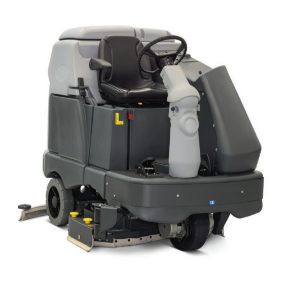
SC6500™
Service Manual
Advance Model Numbers:
56414010
56414011
56414012
56414013
56414014
56414015
Nilfisk Model Numbers:
56414022
56414023
56414024
SC6500 40C
SC6500 40C ECOFLEX
SC6500 40D
SC6500 40D ECOFLEX
SC6500 45C
SC6500 45C ECOFLEX
SC6500 1100D
SC6500 1100C
SC6500 1300D
56414016
SC6500 45D
56414017
SC6500 45D ECOFLEX
56414018
SC6500 48C
56414019
SC6500 48C ECOFLEX
56414020
SC6500 48D
56414021
SC6500 48D ECOFLEX
56414025
SC6500 1300C
56414026
SC6500 1100D ECOFLEX
English
01/15 Form No. 56043168
Advertisement
Table of Contents
Troubleshooting


Need help?
Do you have a question about the SC6500 40C and is the answer not in the manual?
Questions and answers
no water during operation. purge works. no codes. drain and clean tank and filter. hoses clean
Possible causes for no water during operation despite the purge working and no error codes could include:
1. Clogged or Blocked Water Lines – Debris or buildup may be obstructing water flow.
2. Faulty or Disconnected Solenoid Valve – The water solenoid may not be opening properly.
3. Low or Empty Solution Tank – Ensure the solution tank is filled.
4. Kinked or Damaged Hoses – Hoses delivering water may be pinched or damaged.
5. Incorrect Water Flow Settings – Check that the water flow control is properly adjusted.
Inspect these components to identify and resolve the issue.
This answer is automatically generated