
Related Manuals for Nilfisk-Advance SC650 Series


Summary of Contents for Nilfisk-Advance SC650 Series
- Page 1 SC650 Series Service Manual SC650 50000628/50000629/50000630/50000631/ 50000632/50000633/50000634/50000635/ 50000636 English 09/2023 (Rev.01) Form No. 55943414...
-
Page 2: Table Of Contents
Service Manual-SC650 Contents i Table of Contents Table of Contents ................................ i 03 General Information ..............................4 Machine General Description ..........................4 Service Manual Purpose and Field of Application ....................4 Other Reference Manuals ............................4 Conventions ................................5 Service and Spare Parts ............................5 Serial Number Label ...............................5 Safety ..................................6 Visible Symbols on the Machine..........................6 Symbols ..................................6... - Page 3 Service Manual-SC650 Contents ii Troubleshooting ..............................59 Removal and Installation ............................. 60 Specifications ............................... 63 24 Electrical System ..............................64 Functional Description ............................64 Wiring Diagram (Lead-acid) ..........................65 Wiring Diagram (Li-ion) ............................66 Component Locations (Lead-acid) ........................67 Component Locations (Li-ion) ..........................69 Maintenance and Adjustments ..........................
- Page 4 Service Manual-SC650 Contents iii Specifications ..............................113 40 Recovery System............................... 114 Functional Description ............................114 Wiring Diagram ..............................114 Component Locations ............................115 Maintenance and Adjustment ........................... 117 Troubleshooting ..............................119 Removal and Installation ........................... 120 Specifications ..............................121...
-
Page 5: General Information
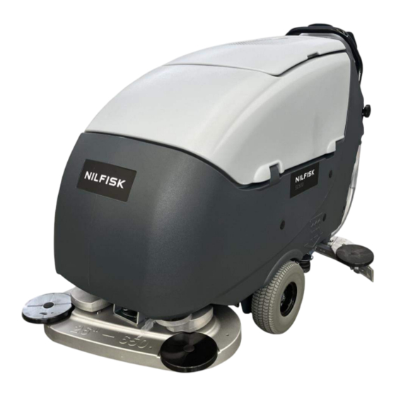
Service Manual- SC650 03 General Information 03 General Information Machine General Description The SC650 is a “walk-behind” industrial machine designed to wash and dry floors in one pass. The machine is powered by on-board batteries, models can be equipped with EcoFlex system. The machine can be equipped with disc brushes system or cylindrical brushes system, a controlled solution flow dosing system and a rear squeegee with rubber blades which vacuums and dries the floor. -
Page 6: Conventions
Service Manual- SC650 03 General Information Conventions Front, rear, left or right are intended with reference to the operator’s position, in driving position. Service and Spare Parts Service and repairs must be performed only by authorized personnel or Advance/Nilfisk Service Centers. The authorized personnel must be trained directly by the manufacturer and use original spare parts and accessories. -
Page 7: Safety
Service Manual- SC650 03 General Information Safety The following symbols indicate potentially dangerous situations. Always read this information carefully and take all necessary precautions to safeguard people and property. Visible Symbols on the Machine WARNING! Carefully read all the instructions before performing any operation on the machine. WARNING! Do not wash the machine with direct or pressurized water jets. -
Page 8: General Safety Instructions
Service Manual- SC650 03 General Information General Safety Instructions Specific warnings and cautions to inform about potential damages to people and machine are shown below. DANGER! Before performing any maintenance, repair, cleaning or replacement procedure disconnect the battery connector. This machine must be used by properly trained operators only. -
Page 9: Machine Lifting
Service Manual- SC650 03 General Information WARNING! When using floor cleaning detergents, follow the instructions on the labels of the detergent bottles. To handle floor cleaning detergents, wear suitable gloves and protections. Do not use the machine as a means of transport. Do not allow the brushes to operate while the machine is stationary to avoid damaging the floor. -
Page 10: Technical Data
Service Manual- SC650 03 General Information Technical Data General technical data SC650 66D SC650 71D SC650 85D SC650 71C Model (2 brushes/pad- (2 brushes/pad- (2 brushes/pad- (2 cylindrical holders) holders) holders) brushes) Power DC 24 V Rated power 1,400 W 1,800 W IP protection class IPX4... - Page 11 Service Manual- SC650 03 General Information Technical data for machines with brush/pad-holder deck SC650 66D SC650 71D SC650 85D Model (2 brushes/pad- (2 brushes/pad- (2 brushes/pad- holders) holders) holders) Cleaning width 660 mm 710 mm 837 mm Brush /Pad diameter 330 mm 355 mm 430 mm...
-
Page 12: Maintenance Schedule
Service Manual- SC650 03 General Information Maintenance Schedule The lifespan of the machine and its maximum operating safety are ensured by correct and regular maintenance. Warning! Maintenance procedures must be performed after the machine is turned off and the battery charger cable is disconnected. In addition, carefully read the instructions in the Safety chapter before performing any maintenance procedure. -
Page 13: Machine Structure
Service Manual- SC650 03 General Information Machine Structure Recovery System Solution System Squeegee System Scrub System Control System Electrical System... - Page 14 Service Manual- SC650 03 General Information Chassis System Drive System...
-
Page 15: Service And Diagnostic Equipment
Service Manual- SC650 03 General Information Service and Diagnostic Equipment Besides a complete set of standard tools, the following instruments are necessary to perform quick check and repairs on machines: Laptop computer charged with the current version of EzParts, Adobe Reader and (if possible) Internet connection. -
Page 16: Dimensions
Service Manual- SC650 03 General Information Dimensions SC650 66D DIMENSIONS SC650 71D DIMENSIONS... - Page 17 Service Manual- SC650 03 General Information SC650 85D DIMENSIONS SC650 71C DIMENSIONS...
-
Page 18: Control System
Service Manual- SC650 04 Control System 04 Control System Functional Description Product No.: 50000628, 50000629, 50000630, 50000631, 50000633,50000634,50000635, 50000636 Label membrane (EB3 Product No.: 50000632 Label membrane (EB3 The machine utilizes a Label membrane (EB3) which represents the user interface to turn on various machine functions and a Main machine controller (EB1) and a UI controller (EB2) to control outputs. - Page 19 Service Manual- SC650 04 Control System The Main machine controller (EB1) manages and drives the following components directly: Drive motor (M3) Vacuum motor (M2) Actuator motor (M6) Brush motors (M1) Solution flow solenoid valve (EV1) Water Pump (M4) Detergent pump (M5) The UI controller (EB2) manages and drives the following components directly: Li-ion battery (LI-BAT) Multicon1...
-
Page 20: Block Diagram
Service Manual- SC650 04 Control System Block Diagram... -
Page 21: Component Locations
Service Manual- SC650 04 Control System Component Locations • Main machine controller (EB1) • UI controller (EB2) • Label membrane (EB3) • Multicon1 • USB socket (USB) Main machine controller (EB1) Label membrane (EB3) UI controller (EB2) - Page 22 Service Manual- SC650 04 Control System Multicon1 USB socket (USB)
-
Page 23: Maintenance And Adjustments
Service Manual- SC650 04 Control System Maintenance and Adjustments Alarm Codes Main Machine Controller (EB1) and UI Controller (EB2) Alarm Codes The Main machine controller and the UI Controller indicate a series of alarms in case of malfunction of one or more systems, and in case of abnormal conditions detected in the input signals. - Page 24 Service Manual- SC650 04 Control System General alarms Alarm code ------------------------ Meaning Condition Effect Service Suggestions Description If it is the NTC error of -------------------- drive system, drive motor NTC ERROR current is limited to 40A. If it is the NTC error of brush system, brush motor current is limited to 35A.
- Page 25 Service Manual- SC650 04 Control System General alarms Alarm code -------------------------- Effect Service Suggestions Meaning Condition Description 1. Check that there are no short ----------------------- circuits in the traction wiring. TRACTION short circuit on 2. If alarm still exists, replace the Function SHORT CIRCUIT traction motor...
- Page 26 Service Manual- SC650 04 Control System General alarms Alarm code Meaning Condition Effect Service Suggestions ------------------------ Description Open circuit on open circuit Solenoid valve Check that there are no open circuits in -------------------- Solenoid valve blocked the Solenoid valve wiring. VALVE.
- Page 27 Service Manual- SC650 04 Control System General alarms Alarm code Meaning Condition Effect Service Suggestions -------------------------- Description Undervoltage The battery voltage Vacuum 1. Check the battery voltage under no- load conditions and under load. ----------------------- on vacuum system blocked remains below certain VACUUM motor value (19.4V for WET...
- Page 28 Service Manual- SC650 04 Control System Battery and Charger Alarm Codes Lead Acid Battery Charger Alarm Codes On-board Lead Acid Battery Charger Alarms Alarm code Meaning Condition Effect Service Suggestions ------------------------ Description Disconnect the AC, turn off the machine Connection Before charging, no Battery charger --------------------...
- Page 29 Service Manual- SC650 04 Control System Li-ion Battery Error Codes Li-ion Battery Error Codes Effect Alarm code condition Service Suggestions ------------------------- Machine action Machine action Description during use during charging Error message Use the machine only on the allowed Too much slope and don’t push it manually.
- Page 30 Service Manual- SC650 04 Control System Li-ion Battery Error Codes Effect Alarm code condition Service Suggestions -------------------------- Machine action Machine action Description during use during charging Error message flashes, Turn off the machine, check the machine disabled. In the ----------------------- overcurrent condition, the accessible wires/connections.
- Page 31 Service Manual- SC650 04 Control System Note: If any other error messages appear on the display of the machine, please try to perform a “machine reset” or a “battery reset”. If the error still exists, call the Nilfisk service. Machines with 1 module: In some battery-related error conditions, the output of the module is disabled, and the machine will switch off, error messages will not appear on the display.
- Page 32 Service Manual- SC650 04 Control System Display setting Black box: Recording of Alarms, Parameters, Partial Operating Time Counter The alarms activated during normal machine operation are stored and can be read in the corresponding log (Alarm Log Screen). SUPERVISOR SETTING The supervisor allows to check some additional information on some machine operating parameters and to adjust some settings according to specific requirements.
- Page 33 Service Manual- SC650 04 Control System TABLE OF MODIFIABLE PARAMETERS Values Code Description Minimum Factory Setting Maximum CHM1 Detergent concentration level 1 0.25 % 0.25 % (1:400) 3 % (1:33) (1:400) CHM2 Detergent concentration level 2 0.25 % 0.80 % (1:125) 3 % (1:33) (1:400) CHAS...
- Page 34 Service Manual- SC650 04 Control System Display, Machine Settings Screen (Continues) Only when on reaching the last parameter “Reset”, and then pressing the EcoFlex button together with the detergent percentage adjustment button will the following hidden parameters be displayed. HIDDEN PARAMETERS Description Min.
- Page 35 Service Manual- SC650 04 Control System Brush type “0” stands for 66disc brush, “1” stands for 71disc brush, “2” stands for 85disc brush and “3” stands for 71cylindrical brush. WARNING: setting this value based on the machine actual configuration, otherwise the extra pressure of the brush will not work correctly PDET Detergent pump mode...
- Page 36 Service Manual- SC650 04 Control System Display, Alarms Log Screen The alarms log screen (Figure 3) function allows you to check any alarms stored on the machine. To return to the main screen (D, Figure 1), press the One-Touch button to select the option “EXIT”, then press the vacuum button Figure 3...
-
Page 37: Removal And Installation
Service Manual- SC650 04 Control System Removal and Installation Main Machine Controller (EB1) Removal/Replacement Refer to step 1-6 in “UI Controller (EB2) and Label membrane (EB3) Removal/Replacement.” After disconnecting the connectors from the UI controller, remove the control panel. Disconnect the following connections from Main machine controller sequentially: ◦... - Page 38 Service Manual- SC650 04 Control System UI Controller (EB2) and Label membrane (EB3) Removal/Replacement UI Controller (EB2) sequentially (Figure 15): ◦ Drive the machine on a level floor. (Q) and (R) USB and UI controller power supply Turn off the machine. connection (H6 and H7) ◦...
- Page 39 Service Manual- SC650 04 Control System Label membrane (EB3) Perform steps 1 to 6 for removal of the UI Controller Disconnect the following connections sequentially: ◦ (a) Flat connection (P4) ◦ (b) Flat connection (P5) 10 Carefully raise the Label membrane (Z), detaching it from the control panel (P) Assembly 11 Assemble the components in the reverse order of disassembly and note the following:...
-
Page 40: Specifications
Service Manual- SC650 04 Control System Specifications Main Machine Controller (EB1) Connectors DC Connections Pin# Description In/Out V ref. I max. Connected to Traction Motor + 0-24V Traction Motor - 0-24V Battery - 100A BAT- Battery + 100A BAT+ Brush Motor+ and Vacuum Motor + M1.1,2 and M2 Brush Motor - M1.1,2... - Page 41 Service Manual- SC650 04 Control System P4: 5557 type, 16-ways Pin# Description In/Out V ref. I max. Connected to Actuator position 0 microswitch <1A M6.m0 Actuator position 1 microswitch <1A M6.m1 Actuator position 2 microswitch <1A M6.m2 RV2_Low <1A RV2.3 RV2_Signal 0-5V <1A...
- Page 42 Service Manual- SC650 04 Control System UI Controller (EB2) Connectors H1: 5557 type, 4-ways Pin# Description In/Out V ref. I max. Connected to CAN_L in/out 2.5V <1A EB1. P3.CAN_L <1A EB1. P3.GND CAN_H in/out 2.5V <1A EB1. P3.CAN_H Key_In <1A EB1.
- Page 43 Service Manual- SC650 04 Control System H4: 5557 type, 8-ways Pin# Description In/Out V ref. I max. Connected to +5V power supply for detergent level sensor <1A DS.2 Detergent level sensor signal 0-5V <1A DS.1 <1A DS.3 H5: 5557 type, 4-ways Pin# Description In/Out...
- Page 44 Service Manual- SC650 04 Control System P4: (2.54 pitch) 11 ways Pin# Description In/Out V ref. I max. Connected to Power supply – common(GND1) in/out <1A Digit 1 button S1 <1A Digit 2 button S2 <1A Digit 3 button S3 <1A Digit 4 button S4 <1A...
-
Page 45: Shop Measurements
Service Manual- SC650 04 Control System Shop Measurements The following tables contain some “real world” shop voltage measurements to help you recognize what “normal” looks like. All voltage values were measured with the black (Negative) voltmeter lead connected to the main battery negative unless otherwise specified. - Page 46 Service Manual- SC650 04 Control System Drive Motor Color Circuit Description Measured Neutral Fwd - Reverse - FWD Max REV Max Initial Initial Drive motor + 0.001v 1.2v 0.001v 25.4v 0.001v Gray Drive motor - 0.001v 0.002v 1.5v 0.001v 15.59v TM+ to 0.001v 1.2v...
- Page 47 Service Manual- SC650 04 Control System Color Circuit Description Measured Comments 8.01v(min flow rate) White Detergent pump power supply + Positive 24v(max flow rate) 0.42v(Stationary) Deck actuator power supply +/- 1.3v (going up) 25.1v (going down) 0.001v v(max flow/min flow rate) Blue Detergent pump power supply - Constant...
- Page 48 Service Manual- SC650 04 Control System Color Circuit Description Measured Comments Blue CAN_L 2.38v (on) 0 v (off) Black 0v (on/off) Green CAN_H 2.57v (on) 0v (off) with lead acid battery Key_In 25.23v (on) 0.001v (off) Color Circuit Description Measured Comments White ACTUATOR POS.0...
- Page 49 Service Manual- SC650 04 Control System Purple RV2 power supply - 0v(neutral/Fwd-initial/Reverse-initial/FWD Max/ REV Max) White RV2 signal 0.508v(FWD Max) 2.6v(Fwd-initial) 2.94v(neutral) 3.2v(Reverse-initial) 5.47v(REV Max) Green RV1 signal 14.88v(Minimum speed) 25.22v(Maximum speed) RV1 power supply - 14.88v(Minimum speed) 16.24v(Maximum speed) Blue RV1 power supply + 25.23v(Minimum speed / Maximum...
- Page 50 Service Manual- SC650 04 Control System Shop Measurements - UI Controller (EB2) Color Circuit Description Measured Comments Blue CAN_L 2.38v (on) 0 v (off) Black 0v (on/off) Green CAN_H 2.57v (on) 0v (off) Key_In 25.23v (on) 0.001v (off) Color Circuit Description Measured Comments Blue...
- Page 51 Service Manual- SC650 04 Control System Color Circuit Description Measured Comments Violet CAN_L for Multicon1 2.49v (on) 0.001v (off) Black DGND 0.006v (on) 0.001v (off) Blue ON/OFF for Multicon1 0.169v (on) 0.03v (off) Green CAN_H for Multicon1 2.68v (on) 0.001v (off) Power supply for Multicon1 25.24v (on) 0.001v (off)
- Page 52 Service Manual- SC650 04 Control System Color Circuit Description Measured Comments Brown BAT+ for Li-ion battery charger 25.5v(charge/ not charge) Lead-acid charge signal 0.04v(charge) 24.9v(not charge) Yellow Li-ion charge signal 0.004v(charge) 25.5v(not charge) Yellow-Black Lead-acid battery charger 11.23v(charge) communication 4.30v(not charge) Color Circuit Description Measured...
- Page 53 Service Manual- SC650 04 Control System Color Circuit Description Measured Comments power supply + for UI controller 25.5v Color Circuit Description Measured Comments Vcc for LEDs 3.31v LED1 Green EcoFlex™system switch led 3.31v(LED off) indicator 1.37v(LED on) LED2 Green Brush/pad-holder release 3.31v(LED off) switch warning light 1.37v(LED on)
- Page 54 Service Manual- SC650 04 Control System Color Circuit Description Measured Comments Power supply + 3.3v Digit 1 button S1 0.01v(not pressed) 3.28v(only when press) Digit 2 button S2 0.01v(not pressed) 3.28v(only when press) Digit 3 button S3 0.01v(not pressed) 3.28v(only when press) Digit 4 button S4 0.01v(not pressed) 3.28v(only when press)
-
Page 55: Chassis System
Service Manual- SC650 10 Chassis System 10 Chassis System Chassis (main parts) The chassis function is primarily performed by the solution tank, the support housings for the wheels and working mechanisms are integrated in the drive motor and the rear frame. ... -
Page 56: Drive System
Service Manual- SC650 20 Drive System 20 Drive system Functional Description Machine movement is provided by the drive motor (M3). The drive motor (M3) also functions as the main support of the machine, and is composed of an electric motor, the reduction unit with differential and the drive wheels. -
Page 57: Component Locations
Service Manual- SC650 20 Drive System Component Locations Forward/reverse gear paddle Maximum speed adjuster (RV1) Front driving wheels Castor Drive motor Drive motor fuse (F3) Main machine controller (EB1) Forward/reverse Maximum speed gear paddle adjuster (RV1) Front driving wheels Drive motor... - Page 58 Service Manual- SC650 20 Drive System Drive motor fuse (F3) Main machine controller (EB1)
-
Page 59: Maintenance And Adjustment
Service Manual- SC650 20 Drive System Maintenance and Adjustment Drive Motor Carbon Brush Check/Replacement Drive the machine to the appointed disposal area and empty the recovery tank with the hose. Place the machine on a hoisting system (if available). Otherwise, drive the machine on a level floor. Switch off the machine. -
Page 60: Troubleshooting
Service Manual- SC650 20 Drive System Troubleshooting Trouble Possible Causes Remedy Battery voltage too low Charge the battery Drive motor fuse (F3) broken Replace The maximum speed potentiometer (RV1) is Replace broken The speed potentiometer (RV2) is broken Replace Maximum speed adjuster incorrectly regulated The machine Replace or broken... -
Page 61: Removal And Installation
Service Manual- SC650 20 Drive System Removal and Installation Speed Potentiometer (RV2) Removal Drive the machine on a level floor, disconnect the battery connector. Follow the step 4~5 of UI Controller Removal in 04 Control System to take out the paddle box. Disconnect the connection (A) and unscrew the nut (B), then completely remove the paddle box. - Page 62 Service Manual- SC650 20 Drive System Speed Potentiometer (RV1) Removal Perform steps 1 to 4 in “Speed Potentiometer (RV2) Removal” section. Unscrew the screw inside the hole of knob (K) and take the knob (K) out. Unscrew the nut (L), and unscrew the screw (M) on the back side of the paddle box front cover. Cut cable tie (H), and disconnect the connection (N) on the paddle box rear cover, then remove the potentiometer (RV1) (O).
- Page 63 Service Manual- SC650 20 Drive System Drive Motor Removal If the recovery tank and/or solution tank contains recovery water: • Drive the machine to the appointed disposal area. • Switch off the machine. • Empty the recovery tank with the hose. •...
-
Page 64: Specifications
Service Manual- SC650 20 Drive System Specifications Description / Model SC650 66D SC650 71D SC650 85D SC650 71C Driving wheel diameter 267 mm Driving wheel specific pressure on the floor (*) 0.45 0.45 0.45 0.48 N/mm2 Castor diameter 100 mm Castor specific pressure on the floor (*) N/mm2 1.03 1.03... -
Page 65: Electrical System
Service Manual- SC650 24 Electrical System 24 Electrical System Functional Description 1. Machine with lead acid battery: The lead acid batteries (1 x 24V or 2 x 12V or 4 x 6V in series) are connected in series by the cables. The battery charger (LA-CH) is connected to the machine by two connectors (C2) (power connection to the batteries) and C3 (3-way signal connection). -
Page 66: Wiring Diagram (Lead-Acid)
Service Manual- SC650 24 Electrical System Wiring Diagram (Lead-acid) Figure 1... -
Page 67: Wiring Diagram (Li-Ion)
Service Manual- SC650 24 Electrical System Wiring Diagram (Li-ion) Figure 2... -
Page 68: Component Locations (Lead-Acid)
Service Manual- SC650 24 Electrical System Component Locations (Lead-acid) • Main machine controller (EB1) • UI controller (EB2) • Lead-acid battery charger (LA-CH) • Battery connections • Lead-acid battery (LA-BAT) • Battery connector (C1) Main machine controller (EB1) Figure 3 UI controller (EB2) Figure 4... - Page 69 Service Manual- SC650 24 Electrical System Battery connector Battery connections Lead-acid battery (LA-BAT) Figure 5 Lead-acid battery charger (LA-CH) Figure 6...
-
Page 70: Component Locations (Li-Ion)
Service Manual- SC650 24 Electrical System Component Locations (Li-ion) • Main machine controller (EB1) • UI controller (EB2) • Li-ion battery charger (LI-CH) • Battery connections • Li-ion battery (LI-BAT) • Battery connector (C1) Main machine controller (EB1) Figure 7 UI controller (EB2) Figure 8... - Page 71 Service Manual- SC650 24 Electrical System Li-ion battery (LI-BAT) Battery connector (C1) Li-ion battery charger (LI-CH) Battery connections Figure 9...
-
Page 72: Maintenance And Adjustments
Service Manual- SC650 24 Electrical System Maintenance and Adjustments Setting the Installed Battery Type Set the machine and the on-board battery charger (where fitted) on the basis of the type of battery to be in- stalled by modifying the BAT parameter as indicated. 1. - Page 73 Service Manual- SC650 24 Electrical System Code BAT Value Installed battery type Wet cell batteries GEL-AGM Generic GEL or AGM batteries GEL EXIDE® type EXIDE ® /SONNENSHINE brand GEL batteries Wet cell batteries GEL-AGM Generic GEL or AGM batteries GEL EXIDE® type EXIDE ®...
- Page 74 Service Manual- SC650 24 Electrical System Battery Installation Turn off the machine. Disconnect the battery connector. 3. Lift the recovery tank cover and check that it is empty; if not, empty it using the drain hose. 4. Grasp the handle and carefully lift the recovery tank. 5.
- Page 75 Service Manual- SC650 24 Electrical System Battery Charging Note: Fully charge the batteries at the end of each shift. If during operation there is only one flashing segment displayed in the battery symbol, stop using the machine and fully recharge the batteries.
- Page 76 Service Manual- SC650 24 Electrical System Checking/Replacing Fuses Refer to step 1-6 in “UI Controller (EB2) and Label membrane (EB3) Removal/Replacement” After disconnecting the connectors from the UI controller, remove the control panel. Check/replace the following fuses (Figure 14): (A) Brush deck fuse F1: (50 A) (B) Vacuum system fuse F2: (30 A) (C) Drive system fuse F3: (60 A) Figure 14...
-
Page 77: Troubleshooting
Service Manual- SC650 24 Electrical System Troubleshooting See the other chapters for previously provided instructions for other electrical system components. Trouble Possible Causes Remedy Charge the batteries or Batteries flat or connections faulty clean the connections The machine is not The batteries are broken Check the battery no-load working... -
Page 78: General Wiring Diagram
Service Manual- SC650 24 Electrical System General Wiring Diagram... - Page 79 Service Manual- SC650 24 Electrical System...
- Page 80 Service Manual- SC650 24 Electrical System...
- Page 81 Service Manual- SC650 24 Electrical System...
-
Page 82: Solution System
Service Manual- SC650 30 Solution System 81 30 Solution System Functional Description The solution system supplies water and detergent to the brush when cleaning the floor. The solution tank is also the main machine body. There is a manual valve on the right side of the tank to close the water supply whenever maintenance must be performed on the machine. -
Page 83: Wiring Diagram
Service Manual- SC650 30 Solution System 82 Wiring Diagram... -
Page 84: Component Locations
Service Manual- SC650 30 Solution System 83 Component Locations Filler shut-off plug Battery compartment liquid drain hole Solution tank Solenoid valve Solution level hose EcoFlex detergent tank Solution filter Detergent pump Solution tap ... - Page 85 Service Manual- SC650 30 Solution System 84 Battery compartment liquid drain hole Solenoid valve EcoFlex detergent tank Detergent pump Detergent level sensor...
-
Page 86: Maintenance And Adjustment
Service Manual- SC650 30 Solution System 85 Maintenance and Adjustment Solution Filter Cleaning Drive the machine on a level floor. Turn off the machine by pressing and holding the switch for nearly a second. Close the solution tap (A) under the machine, behind the left castor. The tap (A) is closed when it is in the position (B) and it is open when it is in the position (C). - Page 87 Service Manual- SC650 30 Solution System 86 Detergent Tank Cleaning (For machine with EcoFlex™ system) Clean the detergent tank according to the following procedure: For standard version detergent tank Drive the machine to the appointed disposal area. Switch off the machine and disconnect the battery connector. Lift the recovery tank.
- Page 88 Service Manual- SC650 30 Solution System 87 EcoFlex™ System Draining (For machine with EcoFlex™ system) Clean the detergent tank as shown in the previous section. To remove residual detergent from the detergent hoses and pump, proceed as follows. Press the switch to start the machine.
-
Page 89: Troubleshooting
Service Manual- SC650 30 Solution System 88 Troubleshooting Trouble Possible Causes Remedy If the machine is first used, it needs some time Wait for 2-3 minutes and check if to wait for the water fill with the tube the solution reaches the brush The solution filter is clogged/dirty Clean the filter Solution supply valve locked in (semi) closed... - Page 90 Service Manual- SC650 30 Solution System 89 Trouble Possible Causes Remedy The EcoFlex system will not Label membrane (EB3) faulty Replace activate Let the detergent pump work for Detergent does not pass the detergent level several minutes and check if the The detergent tank symbol sensor phenomenon still exists.
-
Page 91: Removal And Installation
Service Manual- SC650 30 Solution System 90 Removal and Installation Water Pump Removal Drive the machine to the appointed disposal area. Switch off the machine and disconnect the battery connector. Lift the recovery tank. Cut the cable tie (F), disconnect the connector (A). Loosen the clamps (B) and disconnect the hoses (C) from the water pump (D). - Page 92 Service Manual- SC650 30 Solution System 91 Solenoid Valve (EV1) Removal Drive the machine on a level floor or on a hoisting system to facilitate the disassembly procedures. . After the logo “NILFISK” disappears on the screen, Input the Press the power switch on the machine password by push the “1234”...
- Page 93 Service Manual- SC650 30 Solution System 92 Detergent Pump Removal Drive the machine on a level floor or on a hoisting system to facilitate the disassembly procedure. Switch off the machine and disconnect the battery connector. Lift the recovery tank. Unscrew the two screws (A) and turn over the plate (B)..
-
Page 94: Specifications
Service Manual- SC650 30 Solution System 93 Specifications SC650 SC650 SC650 SC650 Description Solution tank capacity 80 L 1,37/ 2,75/ 5,5 1,62/ 3,25/ 6,5 1,37/ 2,75/ 5,5 Solution flow (max) per 1,27/ 2,55/ 5,1 setting cl/m 3,8l/min cl/m 3,8l/min cl/m 3,8l/min cl/m 3,8l/min EcoFlex system 0.25% ÷... -
Page 95: Scrub System
Service Manual- SC650 34 Scrub System 94 34 Scrub System Functional Description The disc brush system can be started by the operator. The two disc brushes must rotate opposite each other. At the operator’s position, looking from the top of the machine, the right side must be rotated counterclockwise and the left side clockwise. -
Page 96: Wiring Diagram
Service Manual- SC650 34 Scrub System 95 Wiring Diagram... -
Page 97: Component Locations
Service Manual- SC650 34 Scrub System 96 Component Locations Brush motors (M1) Brush deck support Brush deck Brush deck lifting/ lowering actuator Brush Actuator system wiring connection Main machine controller (EB1) Drive hub ... - Page 98 Service Manual- SC650 34 Scrub System 97 Main machine controller (EB1) Actuator system wiring connection Brush motors fuse (F1)
-
Page 99: Maintenance And Adjustments
Service Manual- SC650 34 Scrub System 98 Maintenance and Adjustments Brush Motor Amperage Check Warning! This procedure must be performed by qualified personnel only. Drive the machine on a level floor. Remove the brush. Disconnect the drive system connector (A) on the Main machine (B) to disable machine movement. . - Page 100 Service Manual- SC650 34 Scrub System 99 Check/Replacement/Adjustment of Driving Belts Between Motors and Cylindrical Brushes (For SC650 71C) Check Drive the machine on a level floor. . After the logo “NILFISK” disappears on the screen, input Press the power switch on the machine the password by push the “1234”...
-
Page 101: Troubleshooting
Service Manual- SC650 34 Scrub System 100 Troubleshooting Trouble Possible Causes Remedy The wiring harness between Main machine controller (EB1) and brush motor is Repair damaged The brush motor connector is disconnected Connect All brushes do not turn The brush motor fuse is open Replace The Main machine controller (EB1) is Replace... -
Page 102: Removal And Installation
Service Manual- SC650 34 Scrub System 101 Removal and Installation Brush for SC650 66D/ 71D/ 85D Installation According to the kind of cleaning to be performed, the machine can be equipped either with the brush (A) or the pad-holder (B) with pad (C) together with the appropriate deck. . - Page 103 Service Manual- SC650 34 Scrub System 102 Brush for SC650 71C Installation 1. According to the kind of cleaning to be performed, the machine can be equipped with the brush. , After the logo “NILFISK” disappears on the screen, Input the 2.
- Page 104 Service Manual- SC650 34 Scrub System 103 Brush Deck Removal Drive the machine on a level floor or on a hoisting system to facilitate the disassembly procedures. Remove the brushes/pad-holders according to the procedure shown in the relevant paragraph. Do not remove the cylindrical brushes.
- Page 105 Service Manual- SC650 34 Scrub System 104 Brush Motor for SC650 66D/ 71D/ 85D Removal Remove the brush/pad-holder deck (see the procedure in the relevant paragraph). At the workbench, remove the screw (A) from the reduction unit which has to be disassembled. Remove the hub assembly (B) with a puller.
- Page 106 Service Manual- SC650 34 Scrub System 105 Brush Motor for SC650 71C Removal Remove the cylindrical brush deck (see the procedure in the relevant paragraph). At the workbench, remove the screw (A) from the motor which has to be disassembled. Remove the case (B).
- Page 107 Service Manual- SC650 34 Scrub System 106 Brush Motor Carbon Brushes for SC650 66D/ 71D Removal Remove the brush/pad-holder deck (see the procedure in the relevant paragraph). Rotate cover (A) to open it. Use the tool to take out carbon brush seat (B). Check the carbon brushes (C) for wear.
- Page 108 Service Manual- SC650 34 Scrub System 107 Brush Motor Carbon Brushes for SC650 85D / 71C Removal Remove the brush motor (see the procedure in the relevant paragraph). At the workbench, remove dust and debris from the motor, especially in the area of the protection clamp (A). Open the rubber buckle (E).
- Page 109 Service Manual- SC650 34 Scrub System 108 Brush Deck Lifting/Lowering Actuator Removal . After the logo “NILFISK” disappears on the screen, input Press the power switch on the machine the password by push the “1234” button to reach the menu. Lower the brush/pad-holder deck by pressing the switch Drive the machine to the appointed disposal area and empty the recovery tank with the hose.
-
Page 110: Specifications
Service Manual- SC650 34 Scrub System 109 Specifications Description / Model SC650 66D SC650 71D SC650 85D SC650 71C Cleaning width 660 mm 710 mm 837 mm 703 mm Brush/pad diameter 330 mm 355 mm 430 mm Brush pressure with extra-pressure 21kg 22kg 31kg... -
Page 111: Squeegee System
Service Manual- SC650 38 Squeegee System 110 38 Squeegee System Functional Description The squeegee system cleans the liquid off the floor, which is then collected by the recovery system. The squeegee is mounted on the squeegee bracket and the weight of the squeegee kit presses it down on the floor. The squeegee can be lifted and lowered by the operator manually using lever. -
Page 112: Component Locations
Service Manual- SC650 38 Squeegee System 111 Component Locations Squeegee lift/lowering lever Mounting handwheels Squeegee bumper wheel Squeegee adjusting handwheel Squeegee holder Squeegee blades... -
Page 113: Maintenance And Adjustment
Service Manual- SC650 38 Squeegee System 112 Maintenance and Adjustment Squeegee cleaning 1. Drive the machine to a level floor. 2. Ensure that the machine is off. 3. Lower the squeegee with the lever. 4. Loosen the handwheels and remove the squeegee. 5. -
Page 114: Troubleshooting
Service Manual- SC650 38 Squeegee System 113 Troubleshooting Trouble Possible causes Remedy The recovery water The squeegee is dirty or the squeegee blades are vacuuming is insufficient Clean or repair/replace worn or damaged or there is no vacuuming There is debris under the squeegee blades Remove The squeegee leaves The squeegee blades are worn, chipped or torn... - Page 115 Service Manual- SC650 40 Recovery System 114 40 Recovery System Functional Description The recovery system removes the dirty water from the floor and pipes it to a recovery tank. When the machine is running, the dirty water on the floor is collected by the squeegee blades and collected through the slots in the same, piped through the vacuum hose and into the tank by the airflow created by vacuum motor (M2).
- Page 116 Service Manual- SC650 40 Recovery System 115 Component Locations Recovery tank cover Cover gasket Container with debris collection grid Recovery tank Vacuum grid with automatic shut-off float Squeegee vacuum hose Recovery water drain hose Vacuum motor (M2) ...
- Page 117 Service Manual- SC650 40 Recovery System 116 Squeegee vacuum hose Vacuum motor (M2) Recovery water drain hose Vacuum motor connecting terminals Vacuum motor fuse (F2)
- Page 118 Service Manual- SC650 40 Recovery System 117 Maintenance and Adjustment Recovery Tank Cleaning Drive the machine to the appointed disposal area. Turn off the machine by pressing and holding the switch for nearly a second. Open the cover (A). Drain the water from the tanks with the hoses. Wash with clean water the cover (A), the tanks (B and C) and the vacuum grid with automatic shut-off float (D).
- Page 119 Service Manual- SC650 40 Recovery System 118 Vacuum Motor Current Draw Test Warning! This procedure must be performed by qualified personnel only. Apply the amp clamp (A to one of the vacuum motor wires (B). Press power switch to turn on the machine. Check if the current draw of vacuum motor is between 11A and 18A at 24V.
- Page 120 Service Manual- SC650 40 Recovery System 119 Troubleshooting Trouble Possible causes Remedy Wiring between Main machine controller (EB1) Repair and vacuum motor (M2) damaged Label membrane (EB3) faulty Replace The vacuum motor will Vacuum motor fuse is open Replace not turn on Vacuum motor faulty Check the amperage A failed driver in the Main machine controller (EB1) Replace the Main machine...
- Page 121 Service Manual- SC650 40 Recovery System 120 Removal and Installation Vacuum Motor (M2) Removal If the recovery tank contains recovery water: • Drive the machine to the appointed recovery water disposal area. • Turn off the machine by pressing and holding the switch for nearly a second.
- Page 122 Service Manual- SC650 40 Recovery System 121 Specifications Description Unit Value Recovery tank capacity L/Gal. 80 / 21.1 Vacuum motor technical data V DC Vacuum capacity (normal mode) 12.2 Vacuum capacity (ECO mode) ≈17@24V Vacuum motor current (normal mode) ≈15@20V Vacuum motor current (silent mode)
Need help?
Do you have a question about the SC650 Series and is the answer not in the manual?
Questions and answers