Nilfisk-Advance Advance SC400 Service Manual
Hide thumbs
Also See for Advance SC400:
- Operating manual (2 pages) ,
- Operating manuallines (2 pages) ,
- Instructions for use manual (84 pages)

Subscribe to Our Youtube Channel
Related Manuals for Nilfisk-Advance Advance SC400


Summary of Contents for Nilfisk-Advance Advance SC400
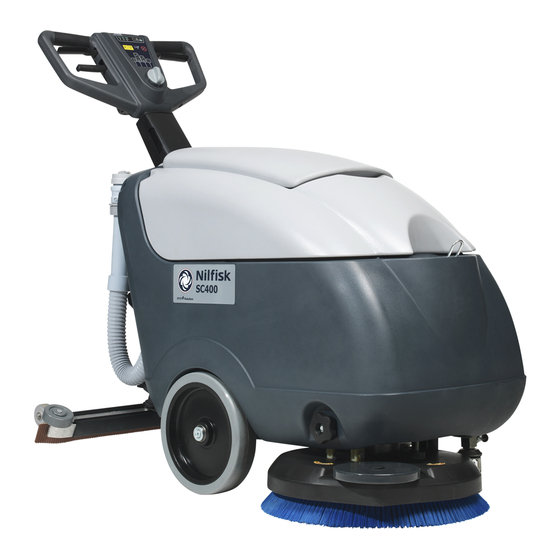
- Page 1 SC400 Service Manual Advance SC400 9087310020 Nilfisk SC400 9087311020 Nilfisk SC400 9087318020 English 2012-11 Form No. 9099624000...
-
Page 2: Table Of Contents
Service Manual – SC400 Table of Contents Table of Contents Table of Contents General Information Machine General Description Service Manual Purpose and Field of Application Other Reference Manuals Conventions Service and Spare Parts Serial Number Label Safety Symbols General Instructions Machine Lifting Machine Transportation Machine Nomenclature (know your machine) -
Page 3: Table Of Contents
Service Manual – SC400 Table of Contents Scrub System, Disc Functional Description Wiring Diagram Component Locations Maintenance and Adjustments Troubleshooting Removal and Installation Specifications Solution System Functional Description Wiring Diagram Component Locations Maintenance and Adjustments Troubleshooting Specifications Squeegee System Functional Description Component Locations Maintenance and Adjustments Troubleshooting... -
Page 4: General Information
Other Reference Manuals User Manual Spare Parts List Model Product Code Nilfisk SC400 9087311020 9099612000 9099613000 Nilfisk SC400 9087318020 Advance SC400 9087310020 9099626000 9099627000 These manuals are available at: − Local Nilfisk-Advance Retailer − Nilfisk-Advance website: www.nilfisk.com www advance-us com... -
Page 5: Conventions
Charg.110-240Vac 50-60 Hz Battery 24 Vdc Type E Scrubber Dryer Conform to: UL STD 583 Certified to: CSA STD C22.2 N.68-92 3084826 “Made in Hungary” Nilfisk-Advance, Inc. Plymouth, MN, USA A Nilfisk-Advance Brand www.advance-us.com Model ....................... Product Nr......................Serial No...................... -
Page 6: Safety
Service Manual – SC400 General Information Safety The following symbols indicate potentially dangerous situations Always read this information carefully and take all necessary precautions to safeguard people and property Symbols Danger! It indicates a dangerous situation with risk of death for the operator. Warning! It indicates a potential risk of injury for people or damage to objects. - Page 7 Service Manual – SC400 General Information Caution! Make sure to follow the safety precautions to avoid situations that may lead to serious injuries, damages to materials or equipments. – Carefully read all the instructions before performing any maintenance/repair procedure. – Before using the battery charger, ensure that frequency and voltage values, indicated on the machine serial number plate, match the mains voltage.
- Page 8 Service Manual – SC400 General Information – Use only brushes supplied with the machine or those specified in the User Manual. Using other brushes could reduce safety – If parts must be replaced, require ORIGINAL spare parts from an Authorised Dealer or Retailer. –...
-
Page 9: Machine Lifting
Service Manual – SC400 General Information Machine Lifting Warning! Do not work under the lifted machine, if it is not securely fixed. Machine Transportation Warning! Before transporting the machine, make sure that: All covers are closed. The recovery tank and the detergent tank are empty. The batteries are disconnected. The machine is securely fastened to the means of transport. -
Page 10: Machine Nomenclature (Know Your Machine)
Service Manual – SC400 General Information Machine Nomenclature (know your machine) Solution tank Recovery tank Solution flow opening/closing valve Solution solenoid valve Recovery tank cover Can holder Handlebar with control panel Recovery water drain plug Recovery water drain hose bracket Recovery water drain hose Electrical component box Battery charger... - Page 11 Service Manual – SC400 General Information Machine Nomenclature (Continues) Recovery tank cover (open) Recovery tank cover gasket Vacuum grid with automatic shut-off float Recovery tank compartment Battery connection Detergent removable filler hose diagram Solution tank filler neck T O F F R O N IN E M A C H...
-
Page 12: Handlebar With Control Panel
Service Manual – SC400 General Information Handlebar with Control Panel Program selection knob / rotary switch Program: brush - solution flow activation Program: brush - vacuum system - solution flow activation Program: vacuum Machine switching off “0” system activation Handlebar inclination Handlebar adjusting lever Brush lever(*) -
Page 13: Service And Diagnostic Equipment
• A copy of the User Manual and Spare Parts List of the machine to be serviced (provided with the machine or available at www.advance-us.com or other Nilfisk-Advance websites). The following equipment is also available at Nilfisk-Advance Centers: • Vacuum water lift gauge, P/N 56205281... -
Page 14: Technical Data
Service Manual – SC400 General Information Technical Data Nilfisk Advance Nilfisk General SC400 43 B SC400 17 B SC400 43 B FULL PKG Solution tank capacity 6.0 US gal (23 liters) Recovery tank capacity 5.5 US gal (21 liters) Machine length 48.4 in (1,230 mm) Machine width with squeegee 28.3 in (720 mm) -
Page 15: Dimensions
Service Manual – SC400 General Information Dimensions 1230 mm (48.4 in) 720 mm (28.3 in) P200074... -
Page 16: Maintenance
Service Manual – SC400 General Information Maintenance The lifespan of the machine and its maximum operating safety are ensured by correct and regular mainte- nance Warning! Read carefully the instructions in the Safety chapter before performing any maintenance procedure. The following table provides the scheduled maintenance The intervals shown may vary according to particu- lar working conditions, which are to be defined by the person in charge of the maintenance. -
Page 17: Control System
Service Manual – SC400 Control System Control System Functional Description The function control is performed with the program The LED electronic board (EBLED) has a set of 3 selection knob/rotary switch (SW1), the machine two-color LEDs The set of 3 LEDs is used to indicate start-up enabling push button (SW2) (which can be either battery charge level or water flow level depend- used simultaneously with the brush levers) and the... -
Page 18: Wiring Diagram
Service Manual – SC400 Control System Wiring Diagram DETERGENT FLOW PUSH-BUTTON (SW3) BRUSH ENABLING FUNCTION ELECTRONIC ROTARY SWITCH (SW1) PUSH-BUTTON (SW2) BOARD (EB1) BRUSH RELEASE FUSE (F4) SIGNAL CIRCUIT FUSE (F3) + 24V JA.1 - Common cathode LED power supply J3.1 - Control power supply J3.2 - Brush function return J3.3 - Vacuum system function return... -
Page 19: Component Locations
Service Manual – SC400 Control System Component Locations • Handlebar with control panel • Machine start-up enabling push button (SW2) • Program selection knob / rotary switch (SW1) • Solution flow push-button (SW3) • LED indicators for: • Function electronic board (EB1) –... -
Page 20: Removal And Installation
Service Manual – SC400 Control System Removal and Installation Function Electronic Board (EB1) Disassembly/Assembly Disassembly Drive the machine on a level floor. Make sure Disconnect the connectors (D) of the function that the machine cannot move independently electronic board (E) Turn the machine program selection knob to “0”... - Page 21 Service Manual – SC400 Control System LED Electronic Board (EBLED) Disassembly/Assembly Disassembly Drive the machine on a level floor. Make sure that the machine cannot move independently. Turn the machine program selection knob to “0” Disconnect the battery connector (red) On the lower side of the handlebar with the control panel, unscrew the screws (A).
- Page 22 Service Manual – SC400 Control System LED Electronic Board (EBLED) Disassembly/Assembly (Continues) If necessary, remove the selector assembly (N) of the machine program selection knob (I), as shown below: • Disconnect the connectors (J) • On the outer side, turn the knob (I) on the position (K) (vacuum system activation). •...
- Page 23 Service Manual – SC400 Control System Machine Start-up Enabling Push-Button Disassembly/Assembly (SW2) Disassembly Drive the machine on a level floor. Make sure Disconnect the connectors (F) of the brush that the machine cannot move independently enabling push-button (G) Turn the machine program selection knob to “0” Remove the screws (H) and remove the switch Disconnect the battery connector (red) If necessary, remove from the housing the...
-
Page 24: Specifications
Service Manual – SC400 Control System Specifications Function Electronic Board (EB1) Specifications FUSES Description Code Type Size Low consumption circuit fuse LITTELFUSE ATOFUSE Brush release circuit fuse OMEGA CT520320 DIP-SWITCHES Description Code DIP1 WET/GEL selector DIP2 Battery charger enabling... - Page 25 Service Manual – SC400 Control System Function Electronic Board (EB1) Connectors J1: MOLEX MINIFIT type, 6-ways vertical Electronic board Description V ref. I max. Connected to in/out Electronic board power supply + Solenoid valve power supply + Solenoid valve power supply - Not used Not used Not used...
- Page 26 Service Manual – SC400 Control System Function Electronic Board (EB1) Connectors (Continues) J2: MOLEX MINIFIT type, 8-ways vertical Description V ref. I max. Electronic board Connected to in/out Brush fuse voltage drop reading + <1A Brush fuse voltage drop reading - <1A Brush electromagnetic switch power supply Vacuum system relay power supply -...
- Page 27 Service Manual – SC400 Control System Function Electronic Board (EB1) Connectors (Continues) J3: MOLEX MINIFIT type, 12-ways vertical Description V ref. I max. Electronic board Connected to in/out Control power supply <1A SW1 - 2 - 3 Brush function return <1A Vacuum system function return <1A...
- Page 28 Service Manual – SC400 Control System Function Electronic Board (EB1) Connectors (Continues) J4: MOLEX MINIFIT type, 2-ways vertical Description V ref. I max. Electronic board Connected to in/out Battery charger enabling power supply CH.1 Battery charger enabling return CH.2 LED ELECTRONIC BOARD CONNECTOR (EBLED B side) JA: MOLEX MINIFIT type, 6-ways vertical Description V ref.
-
Page 29: Controls And Functions
Service Manual – SC400 Control System Controls and Functions a Low consumption circuit fuse (F3): directly downstream of J1.1, it protects all the inner and outer circuits supplied by the electronic board b Battery charger enabling circuit power supply (J4 1): directly downstream of F3 c BATTERY CHARGER enabling (J4.2): if the dip-switch DIP2 is turned to 0 (CH position), the electronic board functions are activated only when the on-board battery charger is NOT connected to the electrical mains;... - Page 30 Service Manual – SC400 Control System Controls and Functions (Continues) g BATTERY PROTECTION function: battery charge status is shown by the 3 LEDs depending on the type of battery (WET/GEL, see step j) according to the following diagram: Transition threshold (V, tolerance ±0.1) Green (fix) <=>...
- Page 31 Service Manual – SC400 Control System Controls and Functions (Continues) BRUSH MOTOR PROTECTION function: through the differential input (J2.1 - J2.2), the voltage drop is read on the BRUSH MOTOR fuse: if the voltage drop exceeds the alarm threshold for more than 30 sec., the J2.3 (BRUSH ELECTROMAGNETIC SWITCH) and J1.2,3 (SOLENOID VALVE) outputs are switched off until their reset by switching off the electronic board When the threshold is exceeded (without delays), the GREEN, YELLOW and RED LEDs flash...
-
Page 32: Electrical System
Service Manual – SC400 Electrical System Electrical System Functional Description Basically the electrical system consists of a function The battery charger (CH) is connected to the batteries electronic board (EB1) which determines the brush (BAT) directly on the – and + terminals and it sup- motor, vacuum system motor and solenoid valve acti- plies the enabling signal to activate the machine func- vation by means of the relevant controls (rotary switch... -
Page 33: Component Locations
Service Manual – SC400 Electrical System Component Locations • Battery charger (CH) • Battery fuse (F0) (only for 9087311020 – • Batteries (BAT) 9087318020 models) • Battery connection connector (C1) • Brush motor fuse (F1) • Battery wiring harness • Vacuum system motor fuse (F2) •... -
Page 34: Maintenance And Adjustments
Service Manual – SC400 Electrical System Maintenance and Adjustments Battery Installation And Battery Type Setting (WET or GEL/AGM) Set the electronic board of the machine and the battery charger according to the type of batteries to be in- stalled (WET or GEL/AGM) as shown below. Machine Setting Disconnect the battery connector (red) Remove the screws (A), then carefully remove the electrical component box cover (B). - Page 35 Service Manual – SC400 Electrical System Battery Installation And Battery Type Setting (WET or GEL/AGM) (Continues) Battery charger setting To set the battery charger, refer to the relevant Manual supplied with the machine. Battery Installation Disconnect the vacuum hose (E) from the squeegee (F) Disconnect the recovery water drain hose (G) from the bracket (H) Open the cover (I) Grasp the recovery tank (J) in the area (K) and slightly raise it...
- Page 36 Service Manual – SC400 Electrical System Battery Charging Note: Charge the batteries when the yellow or red LED turns on, or at the end of each working cycle. Keeping the batteries charged make their life last longer. Caution! When the batteries are discharged, charge them as soon as possible, as that condition makes their life shorter.
- Page 37 Service Manual – SC400 Electrical System Fuse Check and Replacement Fuses in the electric component box Drive the machine on a level floor. Make sure that the machine cannot move independently. Disconnect the battery connector (red) Remove the screws (A), then remove the electrical component box cover (B). Check the following fuses for integrity: •...
-
Page 38: Troubleshooting
Service Manual – SC400 Electrical System Troubleshooting Possible Causes Trouble Remedy The machine is not working The battery connector (C1) is not connected or broken Connect or replace it The batteries (BAT) are discharged or its connections are Charge the batteries or clean/repair the not efficient connections The batteries (BAT) are broken... -
Page 39: Machine Wiring Diagram
Manuale di Assistenza – SC400 Electrical System Machine Wiring Diagram VACUUM SYSTEM BRUSH MOTOR (M2) MOTOR (M1) BATTERY CONNECTOR (C1+) FUNCTION ELECTRONIC BOARD (EB1) 24V BATTERY (BAT) SIGNAL CIRCUIT FUSE (F3) BRUSH RELEASE FUSE (F4) DETERGENT SOLENOID VALVE (EV1) BRUSH MOTOR FUSE (F1) BRUSH ELECTROMAGNETIC LED ELECTRONIC... -
Page 40: Specifications
Service Manual – SC400 Electrical System Specifications Values General Total absorbed power 29 A (0.75 kW) Battery compartment size 13.7x17.7x10.2 in (350x350x260 mm) Battery voltage 24 V Standard batteries (2) 12 V - 50 Ah C5 (AGM) Spiracell Battery charger 100-240 VAC Work autonomy (standard batteries) 1.5 hour... -
Page 41: Recovery System
Service Manual – SC400 Recovery System Recovery System Functional Description The water recovery system removes the dirty water When the automatic float closes and shuts down the from the floor and pipes it to a recovery tank. When vacuum system, the vacuum system motor noise will the machine is running, the dirty water on the floor is increase and the floor will not be dried. -
Page 42: Component Locations
Service Manual – SC400 Recovery System Component Locations • Recovery tank • Vacuum system motor (M2) • Vacuum grid with automatic shut-off float • Electrical component box • Recovery tank cover • Vacuum system motor fuse (F2) • Cover gasket •... -
Page 43: Maintenance And Adjustments
Service Manual – SC400 Recovery System Maintenance and Adjustments Tank and Vacuum Grid Cleaning Drive the machine to the appointed disposal area Turn the machine program selection knob to “0” Open the recovery tank cover (A), then clean and wash the cover, the tank (B) and the vacuum grid (C) with clean water If necessary, release the fasteners (D) and open the grid (C), remove the float (E), clean all the components and then reinstall them... -
Page 44: Troubleshooting
Service Manual – SC400 Recovery System Troubleshooting Possible Causes Trouble Remedy The vacuum system motor (M2) does not The vacuum system motor carbon brushes are worn Replace turn on The rotary switch (SW1) is broken Replace The vacuum system motor is faulty Check the amperage. -
Page 45: Removal And Installation
Service Manual – SC400 Recovery System Removal and Installation Vacuum System Motor Amperage Check Remove the Amp clamp (C) Warning! This procedure must be performed by qualified If the amperage is higher, perform the following personnel only. procedures to detect and correct the abnormal input: Check that the squeegee and the vacuum hose •... - Page 46 Service Manual – SC400 Recovery System Vacuum System Motor Carbon Brush Check/Replacement Check the carbon brushes (F) for wear The Disassembly/Check carbon brushes are worn when: Remove the vacuum system motor (see the • The contact with the motor armature is insuf- procedure in the Vacuum System Motor ficient Disassembly/Assembly paragraph).
- Page 47 Service Manual – SC400 Recovery System Vacuum System Motor Disassembly/Assembly Disassembly Remove the recovery tank Loosen the band (A) and disconnect the hose (B) from the vacuum system motor below Remove the guard (C) Disconnect the connector (D) of the vacuum system motor (E) Remove the screws (F), then lift them from the housing and remove the vacuum system motor (E).
-
Page 48: Specifications
Service Manual – SC400 Recovery System Specifications Values General Recovery tank capacity 5.5 US gal (21 liters) Vacuum system motor power 0.4 hp (300 W) Vacuum water lift (blocked) 47.2 inH O (1,200 mmH... -
Page 49: Scrub System, Disc
Service Manual – SC400 Scrub System, Disc Scrub System, Disc Functional Description The disc brush system can be started by the operator overload The overload is shown by the three battery The disc brush rotates counter-clockwise warning LEDs flashing simultaneously. The brush system, when turning, cleans/washes the The overload is detected by monitoring the current floor surface and assists machine forward movement. -
Page 50: Component Locations
Service Manual – SC400 Scrub System, Disc Component Locations • Disc brush deck • Brush release fuse (F4) • Brush motor (M1) • Machine forward speed adjusting handwheel • Drive hub • Machine straight forward movement adjusting • Electromagnetic switch (K1) handwheel •... -
Page 51: Maintenance And Adjustments
Service Manual – SC400 Scrub System, Disc Maintenance and Adjustments Brush Cleaning Warning! It is advisable to wear protective gloves when cleaning the brush because there may be sharp debris. Remove the brush (as shown in the User Manual) Insert the positioning pin (A) and disengage the machine parking device (B) Clean the brush with water and detergent Check the brush bristles for integrity and wear;... - Page 52 Service Manual – SC400 Scrub System, Disc Machine Forward Movement Adjustment Note: The machine speed and forward movement vary according to the type of floor to be cleaned and the choice of using the brush or the pad. If necessary, perform the following procedure. Adjust the machine speed with the handwheel (A) according to the following procedure: •...
-
Page 53: Troubleshooting
Service Manual – SC400 Scrub System, Disc Troubleshooting Open Circuit • The fuse (F1) determines an open in the supply circuit of the brush deck motor This system allows to prevent the circuits from being damaged under overload conditions • The open in the fuse can be caused by the following: •... -
Page 54: Removal And Installation
Service Manual – SC400 Scrub System, Disc Removal and Installation Brush Motor Amperage Check amperage: Warning! This procedure must be • Check that the brush hub is free from foreign performed by qualified materials (ropes, dirt, ...) preventing it from personnel only. turning •... - Page 55 Service Manual – SC400 Scrub System, Disc Brush Motor Carbon Brush Check/Replacement Check the carbon brushes (H) for wear The Disassembly/Check carbon brushes are worn when: Remove the recovery tank (as shown in User • The contact with the motor armature is insuf- Manual) ficient •...
- Page 56 Service Manual – SC400 Scrub System, Disc Brush Deck Disassembly/Assembly Note: The figure shows the 520 Watt-motor; the 450 Watt-motor is similar. Disassembly Remove the recovery tank and the solution tank (as shown in User Manual) Remove the brush (as shown in the User Manual) If possible, place the machine on a hoisting system. Make sure that the machine cannot move independently Turn the machine program selection knob to “0”...
- Page 57 Service Manual – SC400 Scrub System, Disc Brush Deck Disassembly/Assembly (Continues) 13 Remove the brush deck (J) by turning it as shown in the figure, then lay it on a flat surface. 14 Cut the clamp (K) 15 Remove the four protecting caps (L) of the four electrical connections (M) of the brush motor (N) 16 Mark the position of each of the four electrical connections (M) to make subsequent assembly easier Remove the nuts and disconnect the four electrical connections (M) from the motor 17 Retrieve the brush deck (J)
- Page 58 Service Manual – SC400 Scrub System, Disc Brush Motor Disassembly/Assembly Disassembly Remove the brush deck (see the procedure in the Brush Deck Disassembly/Assembly paragraph). On the lower side of the deck, remove the centre screw (A). Remove the flange (B). Remove the spacer (C) and the key (D) from the hub (E) Remove the screws (F) and remove the brush case (G) Retrieve the brush motor (H)
- Page 59 Service Manual – SC400 Scrub System, Disc Brush Deck Adjuster Disassembly/Assembly Disassembly Remove the brush deck (see the procedure in the Brush Deck Disassembly/Assembly paragraph). On the front right side of the machine, remove the screw (A) and the handwheel (B). Remove the nut (C) and, form inside the wall, remove the deck adjuster (D).
-
Page 60: Specifications
Service Manual – SC400 Scrub System, Disc Specifications Values General Brush/pad diameter 17 in (430 - 432 mm) Brush pressure with full tank and lowered squeegee 77 lb (35 kg) Brush motor power 0.6 hp (450 W) Brush motor speed 155 rpm Brush motor amps 3 - 4 A, No load... -
Page 61: Solution System
Service Manual – SC400 Solution System Solution System Functional Description The solution system supplies the detergent to the is turned to 1 or 2, the brush activation push-button brush when cleaning the floor. The solution tank is (SW2) is pressed and the push-button (SW3) setting is also the main machine body There is a manual valve different from 0 (3 LEDs off) on the left side of the tank to close the water supply... -
Page 62: Component Locations
Service Manual – SC400 Solution System Component Locations • Solution tank • Solenoid valve (EV1) • Solution opening/closing valve • Solution drain and level check hose • Solution filter Solution tank Solution drain and level check hose Solenoid valve (EV1) Solution filter Solution opening/closing valve P200067... -
Page 63: Maintenance And Adjustments
Service Manual – SC400 Solution System Maintenance and Adjustments Solution Filter Cleaning Drive the machine on a level floor. Turn the machine program selection knob to “0” Operating under the machine, in front of the left rear wheel, close the solution valve (A). The valve (A) is closed when it is in the position (B) and it is open when it is in the position (C) Remove the transparent cover (D) and the gasket (E), then remove the filter strainer (F). -
Page 64: Troubleshooting
Service Manual – SC400 Solution System Troubleshooting Possible Causes Trouble Remedy Small amount of solution or no solution The tank filter (optional) is clogged/dirty Clean reaches the brush The solution filter is clogged/dirty Clean The solenoid valve (EV1) is faulty or the electrical Replace the solenoid valve or repair connection is open the electrical connection... -
Page 65: Squeegee System
Service Manual – SC400 Squeegee System Squeegee System Functional Description The squeegee system cleans the liquid off the floor, Each blade has 2 functional edges that can be used which is then collected by the recovery system before it needs replacing The squeegee is equipped with wheels;... -
Page 66: Component Locations
Service Manual – SC400 Squeegee System Component Locations • Squeegee • Squeegee mounting handwheels • Squeegee blades • Squeegee lifting/lowering pedal • Squeegee holder • Gas spring • Blade mounting springs Squeegee mounting handwheels Squeegee lifting/lowering pedal Blade mounting springs Squeegee holder Squeegee Squeegee blades... -
Page 67: Maintenance And Adjustments
Service Manual – SC400 Squeegee System Maintenance and Adjustments Squeegee Cleaning Loosen the handwheels (C) and remove the Warning! It is advisable to wear squeegee (B) protective gloves when cleaning the squeegee Wash and clean the squeegee (B). In particular, because there may be sharp clean the compartments (D) and the vacuum debris. - Page 68 Service Manual – SC400 Squeegee System Squeegee Blade Check and Replacement Disassemble and clean the squeegee (see the procedure in the relevant paragraph) Check that the edge (A) of the front blade and the edge (B) of the rear blade lay down on the same level, along their length;...
-
Page 69: Troubleshooting
Service Manual – SC400 Squeegee System Troubleshooting Possible Causes Trouble Remedy The recovery water vacuuming is The squeegee or the vacuum hose is clogged or Clean/repair/replace insufficient or there is no vacuuming damaged There is debris under the blade Remove The squeegee blade edges are torn or worn Replace The gas spring is not efficient... -
Page 70: Removal And Installation
Service Manual – SC400 Squeegee System Removal and Installation Gas Spring Disassembly/Assembly Disassembly If possible, place the machine on a hoisting system (or on a floor with a suitable step), in order to fully stretch the gas spring (A) of the squeegee support system (B), beyond the support base of the machine (as shown in the figure). -
Page 71: Specifications
Service Manual – SC400 Squeegee System Specifications Values General Machine width with squeegee 28.3 in (720 mm) Gas spring pressure 40,5 Lb (180 Nm) -
Page 72: Wheel System, Non-Traction
Service Manual – SC400 Wheel System, Non-Traction Wheel System, Non-Traction Component Locations • Central wheels on fixed axle • Rear support wheel, when the squeegee is lifted • Parking wheel • Parking wheel positioning pin Parking wheel positioning pin Parking wheel Rear support wheel, when the squeegee is lifted Central wheels on fixed axle... -
Page 73: Specifications
Service Manual – SC400 Wheel System, Non-Traction Specifications Values General Minimum turning radius 29.5 in (750 mm) Diameter of wheels on fixed axle 9.8 in (250 mm) Wheel pressure on the floor 290 psi (2 N/mm...
Need help?
Do you have a question about the Advance SC400 and is the answer not in the manual?
Questions and answers
Hello , mashine just stopped , smells like something burning wiles are blocked , how can i move it to the other place?
If the Nilfisk-Advance SC400 machine has stopped and smells like something is burning, follow these steps before moving it:
1. Turn off the machine and disconnect the batteries.
2. Do not move or work under the machine unless it is securely fixed.
3. Check for possible overload or blockage in the brush or vacuum system.
4. Inspect if any electrical components are damaged (burning smell may indicate motor or fuse issues).
5. If safe, empty the recovery and detergent tanks, ensure all covers are closed, and the machine is securely fastened before transport.
Move the machine only after ensuring it is safe and disconnected from power.
This answer is automatically generated
Floor scrubber intermittent water pickup mostly not advance standing sc1500