
Related Manuals for Balluff BNI IOL-302-S02-Z012-C11


Summary of Contents for Balluff BNI IOL-302-S02-Z012-C11
- Page 1 BNI IOL-302-S02-Z012-C11 IO-Link 1.1 Sensor/Actuator Hub with Extension Port User's Guide...
-
Page 2: Table Of Contents
Safe state of the outputs on pin 2 43hex\ Voltage monitoring 44hex Output monitoring 45hex Setting the serial number 54hex Configuration of the extension port 55hex Configuration: BNI IOL-302-S02-Z012-C11 extended with the same device Configuration of the extension port IO-Link Data... - Page 3 Safe state of the outputs on pin 2 43hex Voltage monitoring 44hex Output monitoring 45hex Setting the serial number 54hex Configuration of the extension port 55hex Configuration: BNI IOL-302-S02-Z012-C11 extended with 22/24 valve terminal Configuration of the extension port IO-Link Data Process Data/Input Data Process Data/ Output Data...
-
Page 4: Notes To The User
Balluff Network Interface / IO-Link Notes to the user About this This manual describes the Balluff IO-Link I/O module, also called a sensor/actuator hub. manual The IO-Link protocol is used to link to the higher-level master module. Functionally this compact, cost-effective module is similar to a passive splitter box; it records digital sensor signals and transmits them over the IO-Link interface. -
Page 5: Safety
Before maintenance, disconnect the device from the power supply. Note In the interests of product improvement, Balluff GmbH reserves the right to change the technical data of the product and the content of this manual at any time without notice. -
Page 6: First Steps
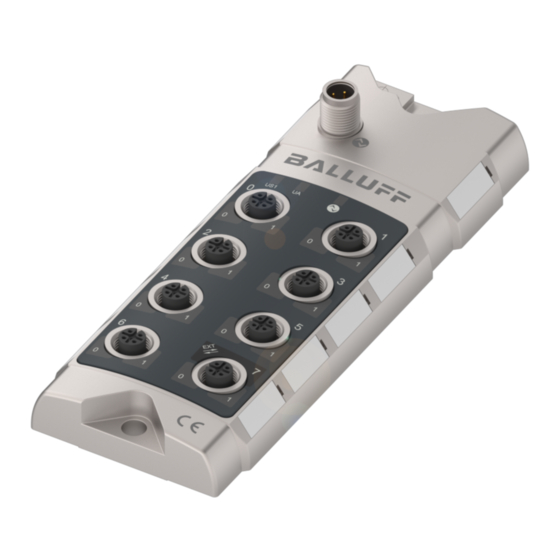
Balluff Network Interface / IO-Link First steps Connection overview Fig. 3.1: Connections 1 Mounting hole Port 6 2 Label 10 Port 4 3 Communication status 11 Port 2 4 Port 1 12 Port 0 5 Port 3 13 IO-Link interface... -
Page 7: Power Supply
Balluff Network Interface / IO-Link First steps Power supply Three different types of connection are used for supplying the module (US1), the sensors (US2) and the actuators (UA). The following connections are available depending on the device type: BNI IOL-302-S02-Z012-C11... -
Page 8: Mechanical Connection
Balluff Network Interface / IO-Link First steps Mechanical The BNI IOL modules are attached using 2 M6 screws and 2 washers. connection Electrical The BNI IOL-... modules do not require their own supply voltage. Supply voltage is provided connection via the IO-Link interface and the higher-level IO-Link master module. You can however use an additional AUX terminal for supplying the sensors and actuators connected to the module. -
Page 9: Digital Sensors / Actuators
Balluff Network Interface / IO-Link First steps Digital sensors / Digital input/output port (M12, A-coded, female) actuators Requirements +24 V, 200 mA PNP-Input 2 / PNP-Output 2 0 V, GND PNP-Input 1 / PNP-Output 1 Note For the digital inputs, the input guideline specified in EN 61131-2, Type 3 applies. -
Page 10: Device Version
Balluff Network Interface / IO-Link First steps Device version Device versions Functionality 16 digital inputs/outputs with single-channel monitoring, IO- BNI IOL-302-S02-Z012-C11 Link V1.1 with extension port Extension port These modules use port 7 in various ways. By default, it is used as a digital I/O slot, where both pin 2 and pin 4 can be used as a digital input or output. -
Page 11: Configuration Overview
Balluff Network Interface / IO-Link Configuration overview Introduction The module can be configured using the extension port in one of five modes, resulting in 20 different configuration possibilities. The following provides detailed technical data preceded by a summary of the essential functions and properties. -
Page 12: Configuration Of The Extension Port
Balluff Network Interface / IO-Link Configuration overview Configuration The following devices may be connected to the extension port: of the extension port Configuration Application Device only (extension port not active) Device with identical device Device with BNI IOL-751-V08-K007 Device with BNI IOL-751-V10-K007 Device with BNI IOL-751-V13-K007 The device connected to the extension port is referred to in the user's guide as the "second... -
Page 13: Data Handling With Extension Port
Balluff Network Interface / IO-Link Configuration overview Data handling If the extension port is enabled, the contents and length of the process data (or ISDU) are with extension calculated as a unification of the process data (or ISDU) provided by both parties. -
Page 14: Configuration: Device Alone, Extension Port Inactive
Balluff Network Interface / IO-Link Configuration: Device alone, extension port inactive Device version This section describes the following device versions. The extension port is not activated. BNI IOL-302-S02-Z012-C11 Configuration The factory default is extension port inactive. of the Value of IDSU-Index... -
Page 15: Process Data/Input Data
Balluff Network Interface / IO-Link Configuration: Device alone, extension port inactive Process The following table shows which types of data are available: Data/Input Data The first two bytes always indicate the input status for all device versions. The following bytes contain the diagnostic information. The order of these bytes is determined, but availability is optional. -
Page 16: Process Data/Output Data
Balluff Network Interface / IO-Link Configuration: Device alone, extension port inactive Process Data/ Outgoing process data are the output status for the device version. Output Data Byte ⚫ ⚫ = available Parameter data/ ISDU Data Access identification Parameter Default Value... -
Page 17: Parameter Data - Device Configuration - Overview
Balluff Network Interface / IO-Link Configuration: Device alone, extension port inactive Parameter data – device configuration – overview ISDU Data Standard Parameter Access rights width Value Index Subindex ⚫ Inversion of the inputs 2 bytes Reading/writing 1-16 ⚫ Safe state on Pin 4... -
Page 18: Safe State Of The Outputs 42Hex, 43Hex
Balluff Network Interface / IO-Link Configuration: Device alone, extension port inactive Safe The safe state parameter makes it possible to configure the outputs in case of a fault. If no IO- state of the Link communication is possible or the "valid flag" of the output process data has not been set outputs by the master, then each output adopts the configured status. -
Page 19: Voltage Monitoring 44Hex
Balluff Network Interface / IO-Link Configuration: Device alone, extension port inactive Voltage Byte monitoring Sub- index Output Byte monitoring Sub- index Setting the The serial number has a factory set value consisting of 16 ASCII characters, e.g. 0E-G550389- serial number 1D-26. -
Page 20: Configuration: Bni Iol-302-S02-Z012-C11 Extended With The Same Device
Balluff Network Interface / IO-Link Configuration: BNI IOL-302-S02-Z012-C11 extended with the same device BNI IOL-302-S02-Z012-C11 with - BNI IOL-302-S02-Z012-C11 Configuration Value of IDSU-Index Configuration of the extension port Device alone (extension port not active) Device with identical device Device with BNI IOL-751-V08-K007... -
Page 21: Process Data/Input Data
Balluff Network Interface / IO-Link Configuration: BNI IOL-302-S02-Z012-C11 extended with the same device Process Byte Data/Input Data Byte Byte www.balluff.com... - Page 22 Balluff Network Interface / IO-Link Configuration: BNI IOL-302-S02-Z012-C11 extended with the same device Byte Extension port Byte Extension port Byte Extension port www.balluff.com...
-
Page 23: Process Data/ Output Data
Balluff Network Interface / IO-Link Configuration: BNI IOL-302-S02-Z012-C11 extended with the same device Process Data/ Byte Output Data Byte Extension port www.balluff.com... -
Page 24: Parameter Data/ Identification Data And Device Parameters
Balluff Network Interface / IO-Link Configuration: BNI IOL-302-S02-Z012-C11 extended with the same device Parameter data/ ISDU Data Access identification Parameter Default Value Sub- width rights Index Index data and index device Vendor ID 2 bytes 0378 parameters Device ID 3 bytes... -
Page 25: Inversion Of The Inputs 40Hex
Balluff Network Interface / IO-Link Configuration: BNI IOL-302-S02-Z012-C11 extended with the same device Inversion of the Byte inputs Sub- index Byte Sub- index Extension port Inversion of port (x): 0 – Normal 1 - Inverted www.balluff.com... -
Page 26: Safe State Of The Outputs On Pin 4 42Hex
Balluff Network Interface / IO-Link Configuration: BNI IOL-302-S02-Z012-C11 extended with the same device Safe The safe state parameter makes it possible to configure the outputs in case of a fault. If no IO-Link state of the communication is possible or the "valid flag" of the output process data has not been set by the outputs on master, then each output adopts the configured status. -
Page 27: Safe State Of The Outputs On Pin 2 43Hex
Balluff Network Interface / IO-Link Configuration: BNI IOL-302-S02-Z012-C11 extended with the same device Safe Byte state of the outputs on Sub- pin 2 index Byte Sub- index Extension port www.balluff.com... -
Page 28: Voltage Monitoring 44Hex
Balluff Network Interface / IO-Link Configuration: BNI IOL-302-S02-Z012-C11 extended with the same device Voltage Byte monitoring Sub- index Byte Sub- index Extension port Output Byte monitoring Sub- index Byte Sub- index Extension port www.balluff.com... -
Page 29: Setting The Serial Number 54Hex
Balluff Network Interface / IO-Link Configuration: BNI IOL-302-S02-Z012-C11 extended with the same device Setting the The serial number has a factory set value consisting of 16 ASCII characters, e.g. serial number 0E-G550389-1D-26. The serial number of the unit cannot be changed. For reasons of compatibility this parameter can be used to assign a custom serial number. -
Page 30: Configuration: Bni Iol-302-S02-Z012-C11 Extended With 22/24 Valve Terminal
Balluff Network Interface / IO-Link Configuration: BNI IOL-302-S02-Z012-C11 extended with 22/24 valve terminal Preface: Devices having the following configuration are covered. All these device versions have diagnostics information in the incoming process data. The only difference is in the max. digital output voltage (200 mA vs. -
Page 31: Process Data/Input Data
Balluff Network Interface / IO-Link Configuration: BNI IOL-302-S02-Z012-C11 extended with 22/24 valve terminal Process Byte Data/Input Data Byte Byte www.balluff.com... -
Page 32: Process Data/ Output Data
Balluff Network Interface / IO-Link Configuration: BNI IOL-302-S02-Z012-C11 extended with 22/24 valve terminal Process Data/ Byte Output Data Byte Valve terminal on the extension port * No function with BNI IOL-751-V13-K007 Byte Valve terminal on the extension port * No function with BNI IOL-751-V13-K007... -
Page 33: Parameter Data/ Identification Data And Device Parameters
Balluff Network Interface / IO-Link Configuration: BNI IOL-302-S02-Z012-C11 extended with 22/24 valve terminal Parameter data/ ISDU Parameter Data Access identification Default Value Sub- width rights Index Index data and index device Vendor ID 2 bytes 0378 parameters 05 0E 72... -
Page 34: Parameter Data/Device Configuration
Balluff Network Interface / IO-Link Configuration: BNI IOL-302-S02-Z012-C11 extended with 22/24 valve terminal Parameter data/ ISDU Data Standard Device Parameter Access rights width Value configuration Index Subindex Inversion of the inputs 2 bytes Reading/writing 1-16 Safe state on Pin 4... -
Page 35: Safe State Of The Outputs 42Hex
Balluff Network Interface / IO-Link Configuration: BNI IOL-302-S02-Z012-C11 extended with 22/24 valve terminal Safe state of The safe state parameter makes it possible to configure the outputs in case of a fault. If no IO- the outputs Link communication is possible or the "valid flag" of the output process data has not been set by the master, then each output adopts the configured status. - Page 36 Balluff Network Interface / IO-Link Configuration: BNI IOL-302-S02-Z012-C11 extended with 22/24 valve terminal Byte Sub- Index Valve terminal on the extension port Byte Sub- Index Valve terminal on the extension port * No function with BNI IOL-751-V13-K007 Byte Sub- Index Valve terminal on the extension port www.balluff.com...
-
Page 37: Safe State Of The Outputs On Pin 2 43Hex
Balluff Network Interface / IO-Link Configuration: BNI IOL-302-S02-Z012-C11 extended with 22/24 valve terminal Safe Byte state of the outputs on Sub- pin 2 index Voltage Byte monitoring Sub- index Byte Sub- index Valve terminal on the extension port www.balluff.com... -
Page 38: Output Monitoring 45Hex
Balluff Network Interface / IO-Link Configuration: BNI IOL-302-S02-Z012-C11 extended with 22/24 valve terminal Output Byte monitoring Sub- index Byte Sub- index Valve terminal on the extension port * No function with BNI IOL-751-V13-K007 Byte Sub- index Valve terminal on the extension port * No function with BNI IOL-751-V13-K007 www.balluff.com... -
Page 39: Setting The Serial Number 54Hex
Balluff Network Interface / IO-Link Configuration: BNI IOL-302-S02-Z012-C11 extended with 22/24 valve terminal Setting the The serial number has a factory set value consisting of 16 ASCII characters, e.g. 0E-G550389- serial number 1D-26. The serial number of the unit cannot be changed. For reasons of compatibility this parameter can be used to assign a custom serial number. -
Page 40: Error Codes And Events
Balluff Network Interface / IO-Link Error codes and events Error codes/ Error code Description errors 0x8011 Index not available 0x8012 Subindex not available 0x8023 Access rejected 0x8033 Parameter value too long 0x8034 Parameter value too short 0x8035 Function not available... -
Page 41: Io-Link Functions
Balluff Network Interface / IO-Link IO-Link functions IO-Link This device can be operated with an IO-Link master according to IO-Link version 1.0, and Version 1.0/ version 1.1. Version-specific functions such as data storage (version 1.1) are only supported in combination with a suitable IO-Link master. -
Page 42: Technical Data
≤ 50 mA Current consumption without load Load current (Pin 1) max. 200 mA Load current per output (Pin 2, Pin 4) max. 200 mA for BNI IOL-302-S02-Z012-C11 Load current extension port (Pin 2) max. 2 A Inputs PNP, type 3 Operating –5 °C …... -
Page 43: Function Indicators
Balluff Network Interface / IO-Link Function indicators Function indicators LED 0 LED 1 LED indicator LED Name Indicator Function module status Green No communication Green, flashing IO-Link communication OK Green Module power OK Undervoltage < 18 V Module is without voltage... -
Page 44: Appendix
Balluff Network Interface / IO-Link Appendix Type code BNI IOL-302-S02-Z012-C11 Balluff Network Interface IO-Link interface Functions 302 = 16 PNP inputs/outputs Variants S02 = with IO-Link 1.1 extension port and single-channel monitoring Mechanical configuration Z012 = Zinc die-cast housing Bus connection and power supply: 1x M12x1 external thread,... -
Page 45: Notes
Balluff Network Interface / IO-Link Notes www.balluff.com... - Page 46 Balluff GmbH Schurwaldstrasse 9 73765 Neuhausen a.d.F. Germany Phone +49 7158 173-0 Fax +49 7158 5010 www.balluff.com balluff@balluff.de...
Need help?
Do you have a question about the BNI IOL-302-S02-Z012-C11 and is the answer not in the manual?
Questions and answers