Table of Contents
Advertisement
Quick Links
USER MANUAL
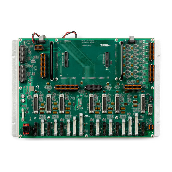
sbRIO-9687
General Purpose Inverter Controller Universal Interface Board
This document describes the features of the sbRIO-9687 and contains information about
connecting, configuring, and operating the device.
Contents
Overview................................................................................................................................... 2
Features..................................................................................................................................... 3
Connectors................................................................................................................................ 4
Switch and Resistor Configuration........................................................................................... 5
Power Considerations............................................................................................................... 6
System Power and Grounding Recommendations............................................................7
Power Input............................................................................................................................... 8
GPIC Signals.............................................................................................................................8
Inverter Signals......................................................................................................................... 9
Inverter CAN Bus Configuration.................................................................................... 12
Inverter Analog Output Configuration............................................................................13
Inverter Driving Signals..................................................................................................14
Analog Input........................................................................................................................... 14
Simultaneous Sampled Analog Input..............................................................................15
Scanned Analog Input..................................................................................................... 24
Analog Output.........................................................................................................................27
Analog Output Configuration......................................................................................... 27
Over-Range Comparators........................................................................................................28
Over-Range Comparator Input Configuration................................................................ 28
Setting the Over-Range Threshold..................................................................................29
Sourcing Digital Input.............................................................................................................30
Sourcing Digital Input Connector................................................................................... 31
Sourcing Digital Input Configuration............................................................................. 32
Sinking Digital Output............................................................................................................ 33
Sinking DO Connector....................................................................................................34
Sinking Digital Output Configuration.............................................................................34
Inverter Digital Signals........................................................................................................... 35
Halt Signals..................................................................................................................... 36
GPIO Signals...................................................................................................................37
LVTTL Lines...........................................................................................................................38
Advertisement
Table of Contents

Related Manuals for National Instruments sbRIO-9687


Summary of Contents for National Instruments sbRIO-9687
-
Page 1: Table Of Contents
USER MANUAL sbRIO-9687 General Purpose Inverter Controller Universal Interface Board This document describes the features of the sbRIO-9687 and contains information about connecting, configuring, and operating the device. Contents Overview........................... 2 Features............................. 3 Connectors..........................4 Switch and Resistor Configuration................... 5 Power Considerations....................... -
Page 2: Overview
Overview Overview of the sbRIO-9687 interface board. The sbRIO-9687 interface board is an addition to the sbRIO-9683 or sbRIO-9684 General Purpose Inverter Controller stacked with the sbRIO-9607 CompactRIO Single-Board Controller. The sbRIO-9687 implements functionality required to control a variety of power conversion cabinets based on Semikron insulated-gate bipolar transistor (IGBT) modules. -
Page 3: Features
Features The sbRIO-9687 interface board provides a wide variety of input/output connectors, breakout connectors for onboard signals, expansion connectors for add-in boards, debugging LEDs, and options for configuration. Inverter connectors • 7 Semikron SKiiP 4 connectors • 7 Semikron SKiiP 3 connectors •... -
Page 4: Connectors
Pads for current-sensing resistors on analog inputs • Easy access for changing low pass filter components Connectors The following table lists the sbRIO-9687 connectors and recommended mating connectors. Refer to the manufacturer for information about using and matching these connectors. Table 1. sbRIO-9687 Connector Types sbRIO-9687... -
Page 5: Switch And Resistor Configuration
The sbRIO-9687 must be configured before it can be used. The board configuration can be set by toggling the onboard DIP switches. Alternatively, the spare resistors in parallel with the switches can be populated with 0 Ω. -
Page 6: Power Considerations
Figure 3. Contact Configuration SW48 Use a sharp tool to toggle the contacts. Power Considerations It is recommended that you perform all resistor changes and switch configurations before the sbRIO-9687 is placed in its final location. 6 | ni.com | sbRIO-9687 User Manual... -
Page 7: System Power And Grounding Recommendations
Info Code sbriocooling Before powering on the sbRIO-9687, make sure there are no wires or metal parts that could touch the surface of the sbRIO-9687. To power the sbRIO-9687, use a +24 V supply capable of delivering the current required by the application. -
Page 8: Power Input
Refer to the sbRIO-9687 Specifications for maximum current consumption. The sbRIO-9687 power input is protected against reverse polarity, and it uses a 10 A fuse to provide protection for overcurrent. Littlefuse Series 314 is recommended, but any compatible fuse can be used. -
Page 9: Inverter Signals
Inverter Signals One of the main functions of the sbRIO-9687 is to provide an interface between the sbRIO-9683 or sbRIO-9684 GPIC controller and up to seven single-phase Semikron inverters. The following tables show the connections between inverter signals and the GPIC. Only one connector from each column of the following tables can be used at a time. - Page 10 AI_3 or AI_4 or AI_5 Temperature AI_0 AI_1 AI_2 AI_3 AI_4 AI_5 Sensor HALT DO_0, DO_1, DO_2, DO_3, DO_4, DO_5, DI_P0.0 DI_P0.1 DI_P0.2 DI_P0.3 DI_P0.4 DI_P0.5 GPIO DI_P0.7 DI_P0.8 DI_P0.9 DI_P0.10 DI_P0.11 DI_P0.12 10 | ni.com | sbRIO-9687 User Manual...
- Page 11 2 of SKiiP 3 GD and Semikube GB are shared. The two full bridge connectors for SKiiP 3 GD and Semikube GD are also in parallel. One full bridge connector reuses signals from three half-bridge connectors. sbRIO-9687 User Manual | © National Instruments | 11...
-
Page 12: Inverter Can Bus Configuration
24 sections for details about signal routing. Note By default, the inverter analog outputs are not connected to the GPIC analog inputs. The onboard switches should be configured before using the sbRIO-9687 interface board. Inverter CAN Bus Configuration The SKiiP 4 inverters have a CAN port for easy diagnosis of the system. -
Page 13: Inverter Analog Output Configuration
12. The return for all analog signals is on pin 13. The interface board can be configured so that the signals are routed to the correct GPIC analog inputs. You can configure the signals by populating resistors on the sbRIO-9687. The options are listed below. Table 9. SKiiP 3 Connector Output Type Selection... -
Page 14: Inverter Driving Signals
The analog input signals can be configured on the sbRIO-9687 in a variety of ways; as a result, it is possible to use the sbRIO-9687 to control most of the power conversion circuits without any additional wiring or circuitry. -
Page 15: Simultaneous Sampled Analog Input
DC link voltage from inverters can be connected to simultaneous sampled AI. The sbRIO-9687 has 16 external analog inputs that can be connected to the GPIC simultaneous sampling analog inputs. Other features of the analog input circuitry include: •... - Page 16 DC Link Voltage Configurable position Simultaneous Analog Input Connectors The sbRIO-9687 interface board includes 16 external simultaneous sampling analog inputs at two connectors, J5 and J11. The following tables provide pin assignment information for the J5 and J11 simultaneous AI breakout connectors.
- Page 17 GPIC. The differential input signal and absolute voltage of each input should be within the input range of each channel. Refer to the sbRIO-9687 Specifications for details. The simultaneous sampling analog inputs are differential, so the input measures the voltage between the positive and negative terminals.
- Page 18 Connecting Current Output Sensors to Simultaneous Analog Input A large selection of current output sensors can be connected to the sbRIO-9687. For current measurements, a current-sensing resistor converts input current into voltage. The burden voltage of the resistor follows the same signal path as the voltage inputs.
- Page 19 Table 14. Simultaneous Sampled AI Current-Sensing Resistors Simultaneous AI 2 W Current-Sensing Resistor 0.25 W Current-Sensing Resistor ssAI0± R141 R140 ssAI1± R121 R120 ssAI2± ssAI3± ssAI4± ssAI5± ssAI6± ssAI7± ssAI8± R304 R303 ssAI9± R266 R265 sbRIO-9687 User Manual | © National Instruments | 19...
- Page 20 R160 Common Mode Filters The sbRIO-9687 uses a high frequency common mode filter for each analog input from external connectors and from Semikron modules. The common mode filter attenuates the inverters' high frequency switching noise, which can interfere with the input signal.
- Page 21 9 for more information. Low Pass Filters The sbRIO-9687 provides a low pass filter for each analog input. The filter has two stages that are populated by default with 10 kΩ resistors and 3.3 nF capacitors. Refer to the sbRIO-9687 Specifications for details about the filter characteristics.
- Page 22 AI connector is within the common mode and differential range listed in the sbRIO-9687 Specifications for each selected gain. The gain should be set to use as much of the GPIC input range as possible. When current signals are converted to voltage with onboard current-sensing resistors, it is preferable to set the gain to the maximum value so that power dissipation from resistors is minimized.
- Page 23 AI5± AI6± AI7± AI8± AI9± AI10± AI11± AI12± AI13± AI14± AI15± Note For analog inputs that are connected to inverter current or voltage outputs, the gain should be set to x1. sbRIO-9687 User Manual | © National Instruments | 23...
-
Page 24: Scanned Analog Input
UDC Input Filter Configurable position Scanned Analog Input Connectors The sbRIO-9687 interface board has seven external scanned analog inputs that are available at breakout connector J14. The following table provides pinout information for the breakout connector. Table 19. J14 Pin Assignments... - Page 25 GND The sbRIO-9687 uses scanned analog input 7 for thermistor measurement; it is not available on the breakout connector. Connecting Voltage Sources to Scanned Analog Input The scanned analog inputs are single ended. One of the input pins is always ground. It is recommended to connect the signal source to the ground pin assigned to each analog input.
- Page 26 Each scanned analog input can be configured to accept unipolar or bipolar input voltages. Refer to the sbRIO-9687 Specifications for details about the input range and accuracy for each setting. Refer to the following table for information about configuring unipolar and bipolar input voltages.
-
Page 27: Analog Output
Connector Onboard Functionality Configurable position Analog output can be used on the sbRIO-9687 to set over-range thresholds. See Over-Range Comparators on page 28 for details about onboard functionality. The analog output lines have the same specifications as the AO lines of the GPIC. For more information, refer to NI 9683 User Manual and Specifications and NI 9684 User Manual and Specifications. -
Page 28: Over-Range Comparators
Over-Range Comparators The sbRIO-9687 interface board has eight over-range comparators that can be connected to analog input signals. The over-range comparators are triggered if the absolute value of the input is over the set voltage. For example, if the threshold is set at 7 V, then the over range is triggered if the input is over 7 V or under -7 V. -
Page 29: Setting The Over-Range Threshold
Analog input signals are connected to the over-range comparators before the gain stage, so the threshold should be set in accordance with the signal level at the sbRIO-9687 input, which is the breakout connector or inverter connector. The over-range circuit has a gain of 0.5 that should be considered when setting the threshold. -
Page 30: Sourcing Digital Input
Sourcing Digital Input The GPIC has 28 sourcing digital inputs grouped in two ports. Each of the sourcing digital inputs is connected to a breakout connector on the sbRIO-9687 interface board. The DI lines 30 | ni.com | sbRIO-9687 User Manual... -
Page 31: Sourcing Digital Input Connector
0 Ω resistors. The following figure shows a block diagram for the sourcing digital input circuitry. Figure 15. Sourcing Digital Input Block Diagram Onboard Functionality DI Port 0... -
Page 32: Sourcing Digital Input Configuration
Sourcing Digital Input Configuration Port 0 of the sourcing digital input is powered at +24 V through the sbRIO-9687 interface board. This power is available at the DI connector on pins 9 and 27. The +24 V can be used to power external circuits or port 1. -
Page 33: Sinking Digital Output
Sinking Digital Output The GPIC has 24 sinking digital outputs. Each sinking DO is connected to the breakout connector. The sbRIO-9687 interface board uses some of the DO lines, which can be disconnected from sbRIO-9687 circuitry by depopulating 0 Ω resistors. -
Page 34: Sinking Do Connector
DO_23 — — Sinking Digital Output Configuration The first seven digital output lines are used on the sbRIO-9687 interface board for inverter signals. See Inverter Digital Signals on page 35 for more details. If sinking digital outputs need to be used externally, they can be disconnected from onboard functionality by depopulating the corresponding resistors. -
Page 35: Inverter Digital Signals
HALT0 HALT1 HALT2 HALT3 HALT4 HALT5 HALT6 Overtemp out GPIO0 GPIO1 GPIO2 GPIO3 GPIO4 GPIO5 GPIO6 Semikube IF_CMN_nHALT R/W HALT0 HALT1 HALT2 HALT3 HALT4 HALT5 HALT6 IF_CMN_GPIO R/W GPIO0 GPIO1 GPIO2 GPIO3 GPIO4 GPIO5 GPIO6 sbRIO-9687 User Manual | © National Instruments | 35... -
Page 36: Halt Signals
GPIO5 Halt Signals The sbRIO-9687 HALT signals are bidirectional. Both ends of the signal line use a pull-up resistor and a transistor for pull-down functionality. Both the controller and the inverter can set or read the status of the signal line. The following diagram shows the HALT signal schematic. -
Page 37: Gpio Signals
DO_6 GPIO Signals The sbRIO-9687 GPIO signals are unidirectional. The signals can only be read by the GPIC. On the inverter side, the signal has a pull-up to 24 V for SKiiP 4, Semikube GB, Semikube GD, Semikube SL GD inverters, and it is open collector for SKiiP 3 GB and SKiiP 3 GD inverters. -
Page 38: Lvttl Lines
3.3 V logical levels. All LVTTL lines are used for onboard functions on the sbRIO-9687. All LVTTL signals are available at the two expansion board connectors. The LVTTL signals are connected directly to the expansion board connectors and have 0 Ω... - Page 39 Low/High DIO23 Hall_1.0 Input R105 DIO24 Hall_1.1 Input R115 DIO25 Hall_1.2 Input R124 DIO26 SCL (I C RH sensor) Input/Output — R125 DIO27 SDA (I C RH sensor) Input/Output — R130 sbRIO-9687 User Manual | © National Instruments | 39...
-
Page 40: Expansion Board
25 pF. The LVTTL DIO channels on the sbRIO-9687 are routed with a 50 Ω impedance trace. It is recommended to route all external circuitry with a similar impedance to ensure the best signal quality. - Page 41 Table 36. LVTTL Expansion Connector Pinout (J8) Signal Signal DIO16 DIO17 DIO18 DIO19 DIO20 DIO21 DIO22 DIO23 DIO24 DIO25 DIO26 DIO27 DIO28 DIO29 DIO30 DIO31 +3.3 V +3.3 V +5 V +5 V sbRIO-9687 User Manual | © National Instruments | 41...
-
Page 42: Expansion Board Power
FPGA power. The current on the +3.3 V rail should not exceed 330 mA. For details, refer to the NI sbRIO-9607 Specifications. The +5 V pin is connected to the sbRIO-9687 internal rail and can supply up to 1 A for both connectors. - Page 43 Feedback_0.5_A Feedback_0.5_B Hall_0.0 Hall_0.1 Hall_0.2 +5 V +5 V Table 38. J10 Feedback Connector Pinout Signal Signal Feedback_1.0_A Feedback_1.0_B Feedback_1.1_A Feedback_1.1_B Feedback_1.2_A Feedback_1.2_B Feedback_1.3_A Feedback_1.3_B Feedback_1.4_A Feedback_1.4_B Feedback_1.5_A Feedback_1.5_B Hall_1.0 Hall_1.1 sbRIO-9687 User Manual | © National Instruments | 43...
-
Page 44: Rs485 Input Signals
+5 V Output The feedback connectors have an +5 V output that can be used for powering encoders. The +5 V output is connected to the sbRIO-9687 internal rail and can supply up to 0.5 A for each connector. Note A short circuit on the +5 V rail could shut down the sbRIO-9687 and may require cycling the +24 V input. -
Page 45: Thermistor
Always On Thermistor The sbRIO-9687 has support for two 10 kΩ thermistors for temperature measurement. The sensors are connected to a 2.5 V reference through a 10 kΩ precision resistor. The thermistor voltage is amplified by a factor of 2 on a gain stage, and then directed to the GPIC scanned analog inputs. -
Page 46: Thermistor Reading
Relative Humidity Sensor For safety, a high voltage system should not be operated when condensation conditions are present. The sbRIO-9687 interface board has a built-in environmental sensor that measures temperature and relative humidity (RH) on the board. Use the following formula to determine the RH on a different point of the cabinet: 17.502 ×... -
Page 47: Relay Connector
DIO27 Relay Connector The sbRIO-9687 provides connections for four relay control outputs. Each output has a relay control DO+ and a current return pin, relay control DO-. The sbRIO-9683 and sbRIO-9684 have current sinking outputs, which means that the relay control DO+ is driven to relay control DO- when the channel is ON. -
Page 48: Display Connector
Display Connector The sbRIO-9687 interface board includes support to drive an Amulet Technologies display that connects to sbRIO using an RS232 interface. The sbRIO-9687 provides power for the display on a separate connector. The following tables provide pinout information for the RS232 and power connectors. - Page 49 General purpose digital output (open collector) Temp_GND Return for temperature output UDC_GND Return for DC link voltage HB_BOT Driving signal for low side IGBT Ground HB_I_GND Return for Phase current output CAN_L CAN low sbRIO-9687 User Manual | © National Instruments | 49...
- Page 50 Return for DC link voltage HB_TOP Driving signal for high side IGBT HB_BOT Driving signal for low side IGBT Rsvd Reserved Ground HB_I Phase current (analog output) HB_I_GND Return for phase current output 50 | ni.com | sbRIO-9687 User Manual...
- Page 51 Signal Name Description +24 V Power for inverter Ground +24 V Power for inverter Ground +24 V Power for inverter Ground CMN_rsvd Digital output signal from inverter (reserved) Ground HALT Halt signal sbRIO-9687 User Manual | © National Instruments | 51...
- Page 52 Driving signal for high side IGBT (Half-Bridge 2) HB2_BOT Driving signal for low side IGBT (Half-Bridge 2) Rsvd Reserved Ground HB2_I Phase current output (Half-Bridge 2) HB2_I_GND Return for phase current (Half-Bridge 2) CAN_H CAN high CAN_L CAN low 52 | ni.com | sbRIO-9687 User Manual...
- Page 53 Ground Temp Temperature (analog signal) HB0_I_GND Return for phase current (Half-Bridge 0) HB0_I Phase current output (Half-Bridge 0) HB1_I_GND Return for phase current (Half-Bridge 1) HB1_I Phase current output (Half-Bridge 1) sbRIO-9687 User Manual | © National Instruments | 53...
-
Page 54: Worldwide Support And Services
NI trademarks. Other product and company names mentioned herein are trademarks or trade names of their respective companies. For patents covering NI products/technology, refer to the appropriate location: Help»Patents in your software, the file on your media, or the National Instruments Patent Notice at . You can find patents.txt ni.com/patents...
Need help?
Do you have a question about the sbRIO-9687 and is the answer not in the manual?
Questions and answers