Advertisement
Quick Links
资料版本:V1.0 归档日期:2014-09-06
IVC1L Series PLC Quick Start
User Manual
This quick start manual is to offer you a quick guide to the design,
installation, connection and maintenance of IVC1L series PLC,
convenient for on-site reference. Briefly introduced in this booklet are the
hardware specs, features, and usage of IVC1L series PLC, plus the
optional parts and FAQ for your reference. For ordering the above user
manuals, contact your Invt distributor or sales office.
1 Introduction
1.1 Model Designation
The model designation is shown in the following figure.
IVC 1L - 16 14 M A
R 1
To Customers:
Thank you for choosing our products. To improve the product and provide
better service for you, could you please fill in the form after the product has
been operated for 1 month, and mail or fax it to our Customer Service Center?
We will send you an exquisite souvenir upon receiving the complete Product
Quality Feedback Form. Furthermore, if you can give us some advices on
improving the product and service quality, you will be awarded a special gift.
Thank you very much!
Invt Control Technology Co., Ltd.
Product Quality Feedback Form
Customer name
Address
Model
Machine SN
Appearance or
structure
Performance
Package
Material
Quality problem
during usage
Suggestion about
improvement
Address: Gaofa Industrial Park, Longjing, Nanshan District, 518055, Shenzhen,
PRC. Tel: +86 755
Sp ecia l functio n. 1 : Ano log
Ou tput m ode . R : re lay o utp ut; T:
tran si sto r ou tpu t; N : n o outp ut
Pow er i npu t mo de (A: 2 2 0a c in pu t; D :
2 4Vdc i npu t); N : n o externa l pow er
i npu t.
Mod ule type .
M: Ba si c mod ule . E: Extensio n modu le
Outpu t p oi nts. In th is exampl e, 1 4.
Inp ut p oi nts. I n this e xampl e, 1 6.
Version n umbe r.
Serie s nu mber. 1 : m ini ; 2 : sma ll;
3 : mid ; 4 : l arg e.
INVT Co ntrol ler mo dul e
Tele
Zip code
Date of use
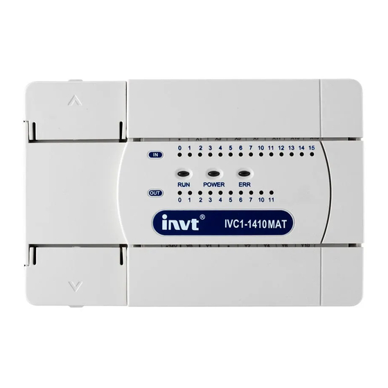
1.2 Outline
The outline of the basic module is shown in the following figure by taking
the example of IVC1L-1614MAR.
P ow er su pplyte m inals
M od e se le ction switch
P ort0
S y s tem s ta tus L E D s
Port1
Port2
PORT0 and PORT1、 PORT2 are communication terminals. PORT0 uses
RS232 mode with Mini DIN8 socket. PORT1 and PORT2 Have Double
RS485. The busbar socket is for connecting the extension module. The
mode selection switch has three positions: ON, TM and OFF.
1.3 Terminal Introduction
The layouts of terminals of different I/O points are shown below:
1.14-point、16-point、24-point
Input terminal:
Output terminal:
2.30-point
Input terminal:
Output terminal:
3.40-point
Input terminal:
Output terminal:
4.60-point
Input terminal:
Output terminal:
5.30-point with anolog
Input terminal:
S/S
X0
X2
X4
X6 X10 X12 X14
X1
X3
X5
X7
X11 X13 X15
Output terminal:
+24
Y0
Y1
Y2
Y3
Y4
COM
COM0
COM1COM2
Inp ut tem in als
In pu t S tatu sLE D s
Extension port
O utput s tatus indicators
O utput teminals
X16
AVI2-
X17
AV2+ AI2+
AV1+ AI1+
Y6
Y10
Y12
Y14
AVO+ AIO+
Y5
Y7
COM3
Y11
Y13
Y15
AVI1-
AO-
1
Advertisement

Subscribe to Our Youtube Channel
Related Manuals for INVT IVC1L Series


Summary of Contents for INVT IVC1L Series
- Page 1 Extension port S y s tem s ta tus L E D s hardware specs, features, and usage of IVC1L series PLC, plus the O utput s tatus indicators optional parts and FAQ for your reference. For ordering the above user manuals, contact your Invt distributor or sales office.
- Page 2 The following table shows the relay output and transistor output. Item Relay output Transistor output IVC1L series PLC basic module has three serial asynchronous Output communication ports: PORT0 and PORT1、PORT2. Supported baud When output state is ON, the circuit is closed; OFF, open...
- Page 3 5.3 Cable Connection And Specification As a terminal dedicated to user programming, PORT0 can be Connecting power cable and grounding cable converted to programming protocol through the mode selection switch. The relationship between PLC operation status and the protocol used The connection of AC power and auxiliary power is demonstrated in the by PORT0 is shown in the following table.
- Page 4 ON position, the RUN indicator should be on. If the ERR indicator is on, the user program or the system is faulty. Loop up in the IV2/IVC1L series PLC Programming Manual and remove the fault. 4. Power on the PLC external system to start system debugging.
Need help?
Do you have a question about the IVC1L Series and is the answer not in the manual?
Questions and answers