Table of Contents
Advertisement
Advertisement
Table of Contents

Subscribe to Our Youtube Channel
Related Manuals for INVT SV-DB100 Series


Summary of Contents for INVT SV-DB100 Series
- Page 2 Thanks for using AC servo drive of the permanent magnet synchronous motor (hereinafter called “servo drive”) from Shenzhen INVT Electric Co., Ltd. Please carefully read and master the user’s manual before proper use. Improper use may cause abnormal running or shorten its service life or even directly damage the drive.
- Page 3 Operational manual for INVT SV-DB100 AC Servo drives Safety precautions Safety precautions The precautions related to safe operation are classified into “Warnings” and “Notes”. Point out potential danger which, if not avoided, may cause physical injury or death. Point out potential danger which, if not avoided, may result in mild or moderate physical injury and damage to the equipment.
- Page 4 Operational manual for INVT SV-DB100 AC Servo drives Safety precautions Wiring: Only qualified electricians are allowed to carry out the wiring. Otherwise there is danger of electrical shock or fire. The grounding terminals of the drive and motor must be grounded with proper techniques.
- Page 5 Operational manual for INVT SV-DB100 AC Servo drives Safety precautions Maintenance and inspection: Before doing any inspection and maintenance, be sure to disconnect the power supply, wait for 15 minutes and then confirm with a multimeter. Otherwise electric shock may occur.
-
Page 6: Table Of Contents
Operational manual for INVT SV-DB100 AC Servo drives Content Content Preface............................I Safety precautions........................II Content ............................1 1 General ............................1 1.1 General technical specifications ..................1 1.2 Nameplate of the servo drive..................4 1.3 Illustration of the nameplate ..................4 1.4 Power specification ......................5 1.5 Illustrations of every parts of the servo drive ..............6 1.6 External dimensions and installations sizes of the servo drive ........6... - Page 7 Operational manual for INVT SV-DB100 AC Servo drives Content 4.5.1 Overview......................23 4.5.2 CN1 pin arrangement and signal explanation ..........24 4.5.3 Standard wiring of the position control mode ..........34 4.5.4 Standard wiring of the speed control mode............35 4.5.5 Standard wiring of the torque control mode ...........36 4.5.6 Detailed instruction of the input and output of CN1 ........37...
- Page 8 Operational manual for INVT SV-DB100 AC Servo drives Content 6.3.3 Special motor control..................96 6.4 I/O management parameters (FP3 group parameters) ..........96 6.4.1Digital input .......................96 6.4.2 Analog input / output adjustment ..............97 6.4.3 Switch input / output settings ................100 6.5 Extension and application (FP4 group parameters) ..........103 6.5.1 Communication setting..................103...
- Page 9 Operational manual for INVT SV-DB100 AC Servo drives Content Appendix C Plug signal of servo motor................149 C.1 Plug of the motor .......................149 C.1.1 Below and including 750: ................149 C.1.2 Above 750W....................149 C.2 Plug of encoder wire....................149 C.2.1 Below and including 750W ................149 C.2.2 Above 750W....................150...
-
Page 10: Content
Operational manual for INVT SV-DB100 AC Servo drives General 1 General 1.1 General technical specifications The standard specifications of the AC permanent magnet synchronous servo drive are listed in the table below: Table 1-1 Standard specifications of servo drive Specifications... - Page 11 Operational manual for INVT SV-DB100 AC Servo drives General Specifications Servo drive 200W~400W 0.75kW~2.0kW 3.0kW~5.5kW Built-in braking resistor, as well as the external Regenerative braking unit braking resistor can be connected AC reactor None Input 13 ways of optical coupling isolation input...
- Page 12 Operational manual for INVT SV-DB100 AC Servo drives General Specifications Servo drive 200W~400W 0.75kW~2.0kW 3.0kW~5.5kW Max torque: 300% of rated torque Frequency 1000Hz response The Max speed is 5000r/min, the Min speed is Speed control 0.1r/min, and the speed regulation range is...
-
Page 13: Nameplate Of The Servo Drive
Operational manual for INVT SV-DB100 AC Servo drives General Specifications Servo drive 200W~400W 0.75kW~2.0kW 3.0kW~5.5kW environmental corrosive, flammable gasses, oil mist, dust conditions Allowable Should be derated if the altitude is higher than operating 1000m altitude ≤5.88m/s , 10~60Hz (not allowed to run at the... -
Page 14: Power Specification
Operational manual for INVT SV-DB100 AC Servo drives General Field Meaning 05: 48VDC 08: 80VDC D1: 110VDC 1: 110VAC 2: 230VAC 4: 400VAC 6: 660VAC Encoder type: 1: 2500-wire 2: 2500-wire 3: 17-bit 4: 17-bit standard increment mode one-loop multiple-loop... -
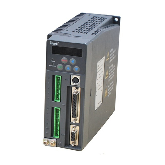
Page 15: Illustrations Of Every Parts Of The Servo Drive
Operational manual for INVT SV-DB100 AC Servo drives General 1.5 Illustrations of every parts of the servo drive Fig. 1-3 Illustrations of every parts of 200W~5.5kW servo drives 1.6 External dimensions and installations sizes of the servo drive Fig. 1-4 External dimensions of 100W~5.5kW servo drive... - Page 16 Operational manual for INVT SV-DB100 AC Servo drives General Table 1-3 External dimensions and installations sizes External dimensions Installation sizes Installation Models hole (mm) (mm) (mm) (mm) (mm) (mm) (mm) SV-DB100-0R2-2 SV-DB100-0R4-2 SV-DB100-0R7-2 SV-DB100-1R0-2 SV-DB100-1R5-2 SV-DB100-2R0-2 SV-DB100-1R0-4 SV-DB100-1R5-4 SV-DB100-2R0-4 SV-DB100-3R0-4...
-
Page 17: Unpacking Inspection
Operational manual for INVT SV-DB100 AC Servo drives Unpacking inspection 2 Unpacking inspection ● Don’t install or use any servo drive that is damaged or has fault parts, otherwise physical injury may occur. Check the following items after unpacking the servo drive and servo motor. -
Page 18: Installation
Operational manual for INVT SV-DB100 AC Servo drives Installation 3 Installation ● Only qualified electricians are allowed to operate on the drive device/system. Ignoring the instructions in “warning” may cause serious physical injury or death or property loss. Only qualified electricians are permitted to design, install, commission and operate on the device/system. -
Page 19: Other Environment Requirements
Operational manual for INVT SV-DB100 AC Servo drives Installation following figure for details: Figure 3.1 Relationship between output current and altitude 3.1.4 Other environment requirements The servo drive can not bear fierce impact or shock. So the oscillation range should be less than 5.88m/s... -
Page 20: Installation Direction And Spacing
Operational manual for INVT SV-DB100 AC Servo drives Installation Fig. 3-3 Schematic diagram of the shelf mounting form of the servo drive 3.2.2 Installation direction and spacing Please install the servo drive vertically and keep sufficient space around it for ventilation. If ℃... -
Page 21: Avoid Intrusion Of Foreign Objects
Operational manual for INVT SV-DB100 AC Servo drives Installation Fig. 3-5 Installation of several servo drives 3.2.3 Avoid intrusion of foreign objects When assembling the control cabinet, do not allow metal chips to intrude into the servo drive. Do not allow oil, water, metal chips and other foreign objects drop into the servo drive through the gaps between the control cabinet or the fan. -
Page 22: Signal And Wiring
Operational manual for INVT SV-DB100 AC Servo drives Signal and wiring 4 Signal and wiring Only qualified electricians are allowed to operate on the drive for the insurance of a safe running of the servo drive. Never carry out any insulation or voltage withstand tests on the cables connecting with the servo drive. -
Page 23: System Configuration
Operational manual for INVT SV-DB100 AC Servo drives Signal and wiring 4.1 System configuration 4.1.1 Connection diagram of the servo drive and external equipment Fig. 4-1 Connection diagram of the servo drive and external equipment Check to ensure the input power supply indicated on the nameplate is the same as the grid before connecting the power supply of the drive. -
Page 24: Emi Filter Selection
Operational manual for INVT SV-DB100 AC Servo drives Signal and wiring Table 4-1 Cable diameter selection Model Cable diameter of the main circuit SV-DB100-0R1-2 0.75~2.0mm SV-DB100-0R2-2 AWG14 to AWG18 SV-DB100-0R4-2 SV-DB100-0R7-2 SV-DB100-1R0-2 SV-DB100-1R5-2 2.0mm SV-DB100-2R0-2 AWG14 SV-DB100-1R0-4 SV-DB100-1R5-4 SV-DB100-2R0-4 SV-DB100-3R0-4 3.5mm... -
Page 25: Braking Resistor Selection
Operational manual for INVT SV-DB100 AC Servo drives Signal and wiring Drives EMI filters SV-DB100-5R5-4 Note: The EMI filter modules in the table means the filter product modules of INVT. 4.1.4 Braking resistor selection Table 4-3 Braking resistor selection Recommended allowed... -
Page 26: Wiring Of The Main Circuit (Plug X1 And X2)
Operational manual for INVT SV-DB100 AC Servo drives Signal and wiring 4.2 Wiring of the main circuit (Plug X1 and X2) 4.2.1 Overview Fig. 4-2 Wiring diagram of the main circuit -17-... -
Page 27: Wiring Diagram Of Single Phase 230V Power Input
Operational manual for INVT SV-DB100 AC Servo drives Signal and wiring 4.2.2 Wiring diagram of single phase 230V power input · The user is required to make this emergency stop protection circuit. · Fit surge absorbing devices on both ends of the electromagnetic contactor winding. -
Page 28: Wiring Diagram Of Three-Phase 230V Power Input
Operational manual for INVT SV-DB100 AC Servo drives Signal and wiring 4.2.3 Wiring diagram of three-phase 230V power input Fig. 4-4 Wiring diagram of three-phase 230V power input -19-... -
Page 29: Wiring Diagram Of Three-Phase 400V Power Input
Operational manual for INVT SV-DB100 AC Servo drives Signal and wiring 4.2.4 Wiring diagram of three-phase 400V power input · The user is required to make this emergency stop protection circuit. Breaker · Fit surge absorbing devices on both ends of electromagnetic contactor winding. -
Page 30: Wiring Of The Encoder (Plug Cn2)
Operational manual for INVT SV-DB100 AC Servo drives Signal and wiring 4.3 Wiring of the encoder (plug CN2) 4.3.1 Overview Fig. 4-6 Wiring of the encoder signal 4.3.2 CN2 pin arrangement and signal definition of the servo drive Fig. 4-7 CN2 pin arrangement Table 4-2 CN2 signal definition table CN2 pin No. -
Page 31: Connection With The Pc Or Host (Cn3 Plug)
Operational manual for INVT SV-DB100 AC Servo drives Signal and wiring CN2 pin No. Definition Cable color Red and white Purple Orange Black and white Brown and white Blue Blue and white Orange and white Purple and white Green Green and white 4.4 Connection with the PC or HOST (CN3 plug) -
Page 32: I/O Signal Wiring (Cn1 Connector)
Operational manual for INVT SV-DB100 AC Servo drives Signal and wiring 4.5 I/O signal wiring (CN1 connector) 4.5.1 Overview Fig. 4-9 Input/output signal connection -23-... -
Page 33: Cn1 Pin Arrangement And Signal Explanation
Operational manual for INVT SV-DB100 AC Servo drives Signal and wiring 4.5.2 CN1 pin arrangement and signal explanation 4.5.2.1 CN1 terminal definition Servo enabling Speed Switching selection 2 Command of the /electrical pulse input control gear selection 1(selected) mode Speed... - Page 34 Operational manual for INVT SV-DB100 AC Servo drives Signal and wiring Z phase Local Alarm clear collector output Position Z phase B phase arrival output output Power supply of Z phase B phase COM- output output the control signal -...
- Page 35 Operational manual for INVT SV-DB100 AC Servo drives Signal and wiring Symbol Pin No. Name Function power supply by themselves. The ground of the internal power supply (except the 24V power supply) of the servo drive, it is also the...
- Page 36 Operational manual for INVT SV-DB100 AC Servo drives Signal and wiring Symbol Name Function Mode emergency stop function: after disconnecting this terminal with COM-, the servo drive cuts off the output, the servo motor coast to stop and Emergency stop warning will occur. After...
- Page 37 Operational manual for INVT SV-DB100 AC Servo drives Signal and wiring Symbol Name Function Mode gain. Parameter FP2.21 is used to select the type of gain switching. See the explanation of FP2.21 and FP2.22 for details. In position control mode, this terminal can be used to disable input of position pulse signal, i.e.
- Page 38 Operational manual for INVT SV-DB100 AC Servo drives Signal and wiring Symbol Name Function Mode In the speed mode, short connecting this terminal with COM- can reverse the direction of the internal speed command and analog Speed speed command. reversing/...
- Page 39 Operational manual for INVT SV-DB100 AC Servo drives Signal and wiring Symbol Name Function Mode Speed Internal speed command (speed option mode)/speed limit (torque mode) or electronic 1/electronic gear (position mode) selected gear option combination of these two terminal signals as...
- Page 40 Operational manual for INVT SV-DB100 AC Servo drives Signal and wiring Symbol Name Function Mode please wait for at least 100ms before entering any command pulse; When SON is disconnected with COM-, the position deviation counter is cleared off. Try best to avoid to starting/stopping the servo drive with this terminal continually.
- Page 41 Operational manual for INVT SV-DB100 AC Servo drives Signal and wiring Symbol Pin No. Name Function Position command External analog input terminals. The input impedance pulse is 10kΩ. The input voltage range is -10V~+10V. A input 1 voltage exceeding ±11V may damage the drive.
- Page 42 Operational manual for INVT SV-DB100 AC Servo drives Signal and wiring Symbol Pin No. Name Function Output the frequency divided encoder signal, Phase A output comply with the standard of TIA/EIA-422-B; The output phase A pulse and phase B pulse is Phase B still orthogonal.
-
Page 43: Standard Wiring Of The Position Control Mode
Operational manual for INVT SV-DB100 AC Servo drives Signal and wiring 4.5.3 Standard wiring of the position control mode Fig. 4-11 Standard wiring of the position control mode -34-... -
Page 44: Standard Wiring Of The Speed Control Mode
Operational manual for INVT SV-DB100 AC Servo drives Signal and wiring 4.5.4 Standard wiring of the speed control mode Fig. 4-12 Standard wiring of the speed control mode -35-... -
Page 45: Standard Wiring Of The Torque Control Mode
Operational manual for INVT SV-DB100 AC Servo drives Signal and wiring 4.5.5 Standard wiring of the torque control mode Fig. 4-13 Standard wiring of the torque control mode -36-... -
Page 46: Detailed Instruction Of The Input And Output Of Cn1
Operational manual for INVT SV-DB100 AC Servo drives Signal and wiring 4.5.6 Detailed instruction of the input and output of CN1 4.5.6.1 Wiring of ON-OFF input circuit Connection diagram when the power supply is self-provided by user: Fig. 4-14 Wiring diagram of ON-OFF input circuit (power supply is self-provided by user) Connection diagram when the local power supply is used: Fig. - Page 47 Operational manual for INVT SV-DB100 AC Servo drives Signal and wiring Fig. 4-16 Wiring diagram of differential pulse input circuit ◆ The maximum frequency of input pulse is 500kHz and the input signal voltage is ±5v; ◆ With the best anti-noise capability, this signal transmit method is recommended as the preferred.
- Page 48 Operational manual for INVT SV-DB100 AC Servo drives Signal and wiring Siemens) is PNP module. The above figure is external 24V power supply connection. If the internal power supply is needed, connect the pin of the positive terminal of 24V...
- Page 49 Operational manual for INVT SV-DB100 AC Servo drives Signal and wiring For all the 3 methods, shielded twisted-pair must be used and the length must be less than 3m. 4.5.6.3 Wiring of the analog input circuit Fig. 4-21 Wiring diagram of the analog input circuit ...
- Page 50 Operational manual for INVT SV-DB100 AC Servo drives Signal and wiring Fig. 4-23 Wiring diagram of ON-OFF output circuit (local power supply) There are 7 digital output circuits in total and all of them adopt the open-collector output as shown in the figure. They can be used to drive the relay coil or optical coupled load.
- Page 51 Operational manual for INVT SV-DB100 AC Servo drives Signal and wiring Fig. 4-25 Wiring diagram of the frequency division output circuit of the open-collector encoder feedback signal Phase A and B of the encoder only provides differential output signal, phase Z provides differential output and open-collector output signals.
-
Page 52: Wiring Of The Electromagnetic Brake
Operational manual for INVT SV-DB100 AC Servo drives Signal and wiring 4.6 Wiring of the electromagnetic brake In the case the servo motor is used in a vertical shaft, the electromagnetic brake can be used to prevent or keep the falling speed of heavy objects when the servo drive is powered off. The... -
Page 53: Running And Operation
Operational manual for INVT SV-DB100 AC Servo drives Running and operation 5 Running and operation 5.1 Running 5.1.1 First powering on Check followings before powering on: 1) Wiring The power supply of the servo drive (R, S, T, r and t) should be connect with proper techniques;... -
Page 54: Self-Test Before Running Of The Servo
Operational manual for INVT SV-DB100 AC Servo drives Running and operation power supply, "AL-PoF” will display on the front panel as the main circuit power-off alarm. it means the bus voltage of the main circuit is 0 or too low. -
Page 55: Trial Jogging
Operational manual for INVT SV-DB100 AC Servo drives Running and operation 5.1.3 Trial jogging Trial jogging can check whether the servo drive and the servo motor are intact and conduct preliminary debugging of the system including the servo drive, servo motor and peripheral equipments. -
Page 56: Running At The Speed Control Mode
Operational manual for INVT SV-DB100 AC Servo drives Running and operation Steps: Complete the connection between the drive and the servo motor. Set FP0.03 to “0”, the position control mode. Ensure the pulse output of the upper controller and adjust FP0.23. Keep the pulse type is the same as that of the upper controller. -
Page 57: Running At The Torque Control Mode
Operational manual for INVT SV-DB100 AC Servo drives Running and operation FP0.42 Speed command input gain FP3.20 Bias voltage of analog input 1 Set according to the requirement Figure 5-2 Simple connection of the speed control mode Steps: Complete the connection between the drive and the servo motor. -
Page 58: Parameter Setting Before Running The Servo
Operational manual for INVT SV-DB100 AC Servo drives Running and operation FP0.60 Torque command selection FP0.62 Torque command input gain FP3.23 Bias voltage of analog input 2 Set according to the requirement FP0.46 Speed limit 1 Figure 5-3 Simple connection of the pulse control mode Steps: Complete the connection between the drive and the servo motor. -
Page 59: Servo Enabling
Operational manual for INVT SV-DB100 AC Servo drives Running and operation 2) Command input Set or enter relevant commands to control the position, speed or torque of the servo motor’s shaft according to the setting of parameter FP0.03. In the position mode: pulse command (3 kinds of input mode), internal torque limit command or external analog torque limit command;... - Page 60 Operational manual for INVT SV-DB100 AC Servo drives Running and operation normally. Coasting to Stop means the drive cuts off output immediately, the motor coasts to rest under the action of inertia, and does not keep in locked state after that. DEC to Stop means the drive outputs reverse torque to make the motor to decelerate to zero speed and, after that, the motor is in a locked state.
-
Page 61: Sequence Diagram
Operational manual for INVT SV-DB100 AC Servo drives Running and operation 5.1.10 Sequence diagram 5.1.10.1 Sequence diagram of power-on and servo ON Fig. 5-4 Sequence diagram of Power-on and servo ON -52-... - Page 62 Operational manual for INVT SV-DB100 AC Servo drives Running and operation 5.1.10.2 Sequence diagram of power loss during running Fig. 5-5 Sequence diagram of power loss during running -53-...
- Page 63 Operational manual for INVT SV-DB100 AC Servo drives Running and operation 5.1.10.3 Servo OFF sequence in a locked state Fig. 5-6 Servo OFF sequence diagram in a locked state -54-...
- Page 64 Operational manual for INVT SV-DB100 AC Servo drives Running and operation 5.1.10.4 Servo OFF sequence in running state Fig. 5-7 Servo OFF sequence diagram in running state -55-...
- Page 65 Operational manual for INVT SV-DB100 AC Servo drives Running and operation 5.1.10.5 Sequence of fault alarm Fig. 5-8 Sequence diagram of fault alarm -56-...
-
Page 66: Display And Operation
Operational manual for INVT SV-DB100 AC Servo drives Running and operation 5.2 Display and operation 5.2.1 Display Fig 5-8 Schematic diagram of the keypad Table 5-1 State of the 3-color indicator Color Function Green Normal running state Fault alarm state... -
Page 67: State Monitoring Mode
Operational manual for INVT SV-DB100 AC Servo drives Running and operation Fig.5-9 Flow chart of front panel operation 5.2.2 State monitoring mode 5.2.2.1 Operation flowchart -58-... - Page 68 Operational manual for INVT SV-DB100 AC Servo drives Running and operation Fig.5-10 Flow chart of state monitoring operation 5.2.2.2 The meaning of state sign The meanings are shown as below: Table 5-3 Function meaning Sign Name Unit Accuracy r/min r00.spd...
-
Page 69: Parameter Setting
Operational manual for INVT SV-DB100 AC Servo drives Running and operation Sign Name Unit Accuracy r25.uE2 FPGA software version r26.uuu Encoder feedback value r27.iA 0.01 Instantaneous value of U phase output current r28.ib 0.01 Instantaneous value of V phase output current Instantaneous value of U phase output current when 0.01... - Page 70 Operational manual for INVT SV-DB100 AC Servo drives Running and operation Fig.5-11 Flow chart of parameter setting operation 5.2.3.2 Parameters list P – position mode; S – speed mode; T – torque mode. The function codes prefixed with sign “*” indicate the setting of these parameters can only take effect after the system resets, restarts, or control circuit is powered off and repowered.
- Page 71 Operational manual for INVT SV-DB100 AC Servo drives Running and operation Function Name Unit Range Default Mode code FP0 Basic control FP0.00 Matching motor selection 200~599 FP0.03* Mode selection FP0.04 Internal servo enabling FP0.05 Jog speed r/min 0.0~1000.0 200.0 Numerator of the frequency FP0.06*...
- Page 72 Operational manual for INVT SV-DB100 AC Servo drives Running and operation Function Name Unit Range Default Mode code electronic gear Denominator of the 4 FP0.32 1~65535 electronic gear FP0.33 Position command filter time 0.0~1000.0 Speed command/speed limit FP0.40 selection (r/min)/ FP0.42...
- Page 73 Operational manual for INVT SV-DB100 AC Servo drives Running and operation Function Name Unit Range Default Mode code mechanical resonance FP1.21 0.0~3000.0 frequency mechanical resonance FP1.22 0.0~3000.0 frequency FP1.23 trap wave center frequency 50.0~3000.0 3000.0 FP1.24 trap wave width 1.0~1000.0 50.0...
- Page 74 Operational manual for INVT SV-DB100 AC Servo drives Running and operation Function Name Unit Range Default Mode code FP3.30 AO 1 selection FP3.31 Voltage gain of analog output 1 0~1000 FP3.32 AO 2 selection FP3.33 Voltage gain of analog output 2 0~1000 FP3.34...
-
Page 75: Auxiliary Functions
Operational manual for INVT SV-DB100 AC Servo drives Running and operation Function Name Unit Range Default Mode code FP9 Factory parameters FP9.00 Factory password 5.2.4 Auxiliary functions There are two auxiliary functions: 1. Jogging trial function 2. Function of parameters restoration These functions can be selected by pressing 5.2.4.1 Operation flowchart for jogging trial... -
Page 76: Alarm Display
Operational manual for INVT SV-DB100 AC Servo drives Running and operation Fig.5-10 Flow chart of default parameter function restoration operation 5.2.5 Alarm display When the servo drive runs abnormally, it will perform fault alarm or warning protection. At this time the panel will display the fault alarm or warning identifier. -
Page 77: Alarm Clearance
Operational manual for INVT SV-DB100 AC Servo drives Running and operation Sign Name Drive overtemperature fault Software overcurrent fault Over-pulse fault Communication fault Write/read overtime fault Brake overload fault IPM module fault The power input phase loss fault er-inE Inertia identification fault... -
Page 78: Detailed Parameter Description
Detailed parameter description Operational manual for INVT SV-DB100 AC Servo drives 6 Detailed parameter description Sign description: P – position mode; S – speed mode; T – torque mode. The setting of the parameters marked with * can only take effect when the control circuit is powered-off and repower-on. - Page 79 Detailed parameter description Operational manual for INVT SV-DB100 AC Servo drives internal torque command or external analog torque command. Position/speed mode: The position mode and speed mode can be switched with the control mode switching terminal (MCH pin “1”). Note: For safety, after changing the MCH...
- Page 80 Detailed parameter description Operational manual for INVT SV-DB100 AC Servo drives Position/torque mode: The position mode and torque mode can be switched with the control mode switching terminal (MCH pin “1”). Note: For safety, after changing the MCH terminal input...
- Page 81 Detailed parameter description Operational manual for INVT SV-DB100 AC Servo drives disconnected with COM-) 1(the terminal is Enabling running connected with COM-) (ON) 0(the terminal is Enabling running disconnected with COM-) (ON) 1(the terminal is Enabling running connected with COM-)
- Page 82 Detailed parameter description Operational manual for INVT SV-DB100 AC Servo drives FP0.07 Note: In the position control mode, if the encoder output signal of the preceding stage servo motor is used as the position pulse command input of the succeeding stage servo drive, i.e.
- Page 83 Detailed parameter description Operational manual for INVT SV-DB100 AC Servo drives Resistance of the Setting Available Default Unit FP0.14 external braking range mode resistor 1~100 Ω Setting Available Power of the external Default Unit FP0.13 range mode braking resistor 0~1500...
- Page 84 Detailed parameter description Operational manual for INVT SV-DB100 AC Servo drives Retention pulse pulse Analog speed command 0.01 voltage Analog torque command 0.01 voltage Setting Parameter meaning Accuracy Unit value Main circuit power bus voltage Control circuit power bus voltage Effective value of current 0.01...
-
Page 85: Position Control
Detailed parameter description Operational manual for INVT SV-DB100 AC Servo drives Instantaneous value of U phase output current when a 0.01 fault occurs Instantaneous value of phase V output current when a fault 0.01 occurs Bus voltage when a fault occurs Drive serial No. - Page 86 Detailed parameter description Operational manual for INVT SV-DB100 AC Servo drives Pulse + pulse sign sign FWD/REV pulse pulse train sign Orthogonal pulse encoder sign pulse Remark: The pulse direction of the parameter can be reversed by FP0.24. Please refer to FP0.24 for detailed information.
- Page 87 Detailed parameter description Operational manual for INVT SV-DB100 AC Servo drives Denominator of Setting Available Default Unit FP0.30 the 2 electronic range mode gear 1~65535 Denominator of Setting Available Default Unit FP0.31 the 3 electronic range mode gear 1~65535 Denominator of...
-
Page 88: Speed And Torque Control
Detailed parameter description Operational manual for INVT SV-DB100 AC Servo drives l :Feed rate corresponding to per pulse (mm/pulse); :Feed rate corresponding to per revolution of the motor (mm/rev). I.e. in this example, =50, Set FP0.25 to 50 and FP0.26 to 3. - Page 89 Detailed parameter description Operational manual for INVT SV-DB100 AC Servo drives Detailed instruction: Setting Control Function value Input Instruction mode name method FP0.40 Select the internal multi-stage speed by the speed selection terminal of CN1(Pin 34 and 17 of SC1 and SC2 )
- Page 90 Detailed parameter description Operational manual for INVT SV-DB100 AC Servo drives limit 1 FP0.47 Speed limit 2 FP0.48 Speed limit 3 FP0.49 Speed limit 4 Please refer to the detailed instruction of FP0.46, FP0.47, FP0.48 and FP0.49. Note: The speed limit depends on the...
- Page 91 Detailed parameter description Operational manual for INVT SV-DB100 AC Servo drives Input voltage x FP0.42 Speed r/min 5000 FP0. 42=500(r/min)/v 2500 FP0. 42 =250 (r/min)/v -10.0V 10.0V Input voltage of analog 1 -2500 -5000 Note: 1. Analog input VA is the input signal from analog speed/speed limit terminal.
- Page 92 Detailed parameter description Operational manual for INVT SV-DB100 AC Servo drives Internal Available Setting range Default Unit FP0.47 speed/speed limit mode -6000.0~6000.0 100.0 r/min Detailed instruction: The servo drive provides 4 stages of internal speed command/internal speed limit: Control Setting value...
- Page 93 Detailed parameter description Operational manual for INVT SV-DB100 AC Servo drives Internal Available Setting range Default Unit FP0.49 speed/speed limit mode -6000.0~6000.0 100.0 r/min Detailed instruction: The function of the parameters is the same as that of FP0.46 and FP0.47.
- Page 94 Detailed parameter description Operational manual for INVT SV-DB100 AC Servo drives range mode 0~1000 Setting Available Default Unit FP0.57 S curve DEC time range mode 0~1000 Detailed instruction: In a case of internal reference speed command, this parameter is used to set the duration of the circular arc segment during S curve decelerating and thus to achieve the goal of smoothly stopping.
- Page 95 Detailed parameter description Operational manual for INVT SV-DB100 AC Servo drives Setting Control Function value Input Instruction mode name method FP0.04 Set the required torque by setting Internal FP0.66. torque Please refer detailed command instruction of PA. 11. The output torque can be controlled...
- Page 96 Detailed parameter description Operational manual for INVT SV-DB100 AC Servo drives Please refer detailed instruction. Note: Please note that in the torque mode; do not allow the motor to run under the condition of negative load. Torque Setting Default Unit Available mode FP0.62...
-
Page 97: Self-Turning Control Parameters (Fp1 Group Parameters)
Detailed parameter description Operational manual for INVT SV-DB100 AC Servo drives This parameter is used to set the time constant of the 1 order low-pass filter corresponding to the torque command. By setting this parameter, the actual output torque changes more gently in cases the torque command changes largely. See the... - Page 98 Detailed parameter description Operational manual for INVT SV-DB100 AC Servo drives Setting Available Machine rigidity Default Unit FP1.03 range mode setting 0~31 Detailed instruction: The bigger the value is, the faster response and higer rigidty and easier vibration. In stable system, higer rigidity setting makes fast response.
-
Page 99: Adaptive Vibration Control
Detailed parameter description Operational manual for INVT SV-DB100 AC Servo drives Setting Available Mechanical Default Unit FP1.06 range mode movement 0.5~10 Detailed instruction: In position mode,if the inertia identification is valid, the parameter can limit the maximum running revolutions in each cycle. - Page 100 Detailed parameter description Operational manual for INVT SV-DB100 AC Servo drives Note: 1. When the speed reaches above 30r/min, the measuring value will be correct. 2. This function is only for read and can not be set. The user can set the frequency of the notch filter according to the function code to remove the resonance.
-
Page 101: Motor Control Parameters (Fp2 Group Parameters)
Detailed parameter description Operational manual for INVT SV-DB100 AC Servo drives 0.00~1.00 0.00 Detailed instruction: Please refer to FP1.23, FP1.24 and FP1.25. Using the 1 and 2 notch filters at the same time can suppress 2 mechanical resonant. 6.3 Motor control parameters (FP2 group parameters) 6.3.1 Gain... - Page 102 Detailed parameter description Operational manual for INVT SV-DB100 AC Servo drives This parameter is used to set the time constant of the speed detect filter. Setting Available Default Unit FP2.04 torque filter range mode 0.00~25.00 0.84 Detailed instruction: This parameter is used to set the time constant of torque filter. Refer to 7.1.2.
-
Page 103: Gain Switching
Detailed parameter description Operational manual for INVT SV-DB100 AC Servo drives range mode filter time constant 0.00~60.00 0.50 Detailed instruction: This parameter is used to set the speed feed-forward filter time constant. Setting Available Torque feed-forward Default Unit FP2.12 range... - Page 104 Detailed parameter description Operational manual for INVT SV-DB100 AC Servo drives PLC is the wiring terminal of CN1 (pin 36). Below is its relationship with COM-: 0: OFF(the terminal is disconnected with COM-); 1: ON (the terminal is connected with COM-).
-
Page 105: Special Motor Control
Detailed parameter description Operational manual for INVT SV-DB100 AC Servo drives FP2.22 gain switching Retention pulse threshold Speed threshold 6.3.3 Special motor control Setting Available Speed compensation Default Unit FP2.47 range mode threshold 0~20000 pulse Setting Available Default Unit FP2.48... -
Page 106: Analog Input / Output Adjustment
Detailed parameter description Operational manual for INVT SV-DB100 AC Servo drives bit. The corresponding relationships between each bit and the digital quantity are: BIT4 BIT3 BIT2 BIT1 BIT0 Details (Refer to chapter 4.5.8.3 for detailed description of the signs of the digital... - Page 107 Detailed parameter description Operational manual for INVT SV-DB100 AC Servo drives For example, after the analog setting signal is connected into the AI terminal (VA) of the drive, even though the analog setting signal is 0, the front panel displays the analog speed command voltage (dp-An1) is 0.02V.
- Page 108 Detailed parameter description Operational manual for INVT SV-DB100 AC Servo drives Torque given Reserve Setting Available Default Unit FP3.31 Voltage gain of AO 1 range mode 0~1000 Setting Available Default Unit FP3.33 Voltage gain of AO 2 range mode 0~1000...
-
Page 109: Switch Input / Output Settings
Detailed parameter description Operational manual for INVT SV-DB100 AC Servo drives Note: 1. AO1 means the signal output from the AO1 terminal (AO1 pin21) and AO1 means the signal output from the AO2 terminal (AO2 pin25). The output signal has no directional properties and stands for the absolute value of the setting signal. - Page 110 Detailed parameter description Operational manual for INVT SV-DB100 AC Servo drives range mode shield Detailed instruction: This parameter is used to set the input signals of the forward travel limit terminal (PSL pin 3) and reverse travel limit terminal (RVL pin 4) of CN1 are active or inactive. If the function of the travel limit switch needs to be shielded, set this parameter.
- Page 111 Detailed parameter description Operational manual for INVT SV-DB100 AC Servo drives 2. The clearance of AL-EST: Please ensure there is no danger, and then clear the alarm signal (i.e. connecting EMG with COM). If the alarm is displayed to be cleared (CLA function), it is necessary to enable the servo drive again, and the system will work normally.
-
Page 112: Extension And Application (Fp4 Group Parameters)
Detailed parameter description Operational manual for INVT SV-DB100 AC Servo drives for a period of time so that the motor will not rotate during the action of the relay. Refer to chapter 5.1.10 for the sequence relationship. Braking delay time of... - Page 113 Detailed parameter description Operational manual for INVT SV-DB100 AC Servo drives as follow: 0:9600bps; 1:19200bps; 2:38400bps; 3:57600bps; 4:115200bps. Setting Available Communication parity Default Unit FP4.04 range mode mode 0~17 Detailed instruction: 0: None (8, N, 1) for RTU; 1: Even (E, 8, 1) for RTU;...
- Page 114 Detailed parameter description Operational manual for INVT SV-DB100 AC Servo drives the system will wait until the response delay time is over before transmitting data to the upper PC. Setting Available Communication Default Unit FP4.06 range mode overtime fault time 0~60.0...
-
Page 115: Alarm Threshold Setting
Detailed parameter description Operational manual for INVT SV-DB100 AC Servo drives 6.5.2 Alarm threshold setting Setting Available Stopping mode Default Unit FP4.30 range mode selection Detailed instruction: When the servo is turned OFF and when an fault alarm occurs, this parameter is used... -
Page 116: Factory Parameters (Fp9 Group Parameters)
Detailed parameter description Operational manual for INVT SV-DB100 AC Servo drives default value of drives below 750W (including) is 5000.0 and above is2500.0. The setting range of drives below 2.0kW is 0~5000.0 and above 2.0kW is 0~3000.0. Setting Available Default Unit FP4.32... -
Page 117: State Monitoring
Detailed parameter description Operational manual for INVT SV-DB100 AC Servo drives Detailed instruction: This parameter is the factory parameter password. The factory parameters are not open to the user. The user is advised not to try to get into this group of factory parameters. - Page 118 Detailed parameter description Operational manual for INVT SV-DB100 AC Servo drives Count and display the lower 5 bits of the number of the accumulated input pulses. The displayed number is the pulse number before being amplified by the electronic gear. The displayed content may not be consistent with the accumulated number of the feedback pulses, with a sign bit.
- Page 119 Detailed parameter description Operational manual for INVT SV-DB100 AC Servo drives Detailed instruction: In the torque mode: display the voltage value of the analog torque command. In the speed mode: display the voltage value of the analog torque limit. Bus voltage of main...
- Page 120 Detailed parameter description Operational manual for INVT SV-DB100 AC Servo drives pulse r16-PoS pulse Detailed instruction: Display the position of the rotor relative to Z pulse in one revolution. The unit is pulse. Symbol Accuracy Unit r17-inE Inertia ratio of load...
- Page 121 Detailed parameter description Operational manual for INVT SV-DB100 AC Servo drives Symbol Accuracy Unit r23-tt Motor temperature ℃ r23-tt Detailed instruction: Display the current temperature of motor. Symbol Accuracy Unit r24-uE1 DSP software version r24-uE1 Detailed instruction: Display the version number of current DSP software.
- Page 122 Detailed parameter description Operational manual for INVT SV-DB100 AC Servo drives Instantaneous value of Symbol Accuracy Unit r30-ibF phase V output current r30-ibF 0.01 when an fault occurs Detailed instruction: Display the instantaneous value of phase V output current when a fault occurs.
-
Page 123: Gain Adjustment
Gain adjustment Operational manual for INVT SV-DB100 AC Servo drives 7 Gain adjustment 7.1 General method for adjusting parameters When the servo system oscillates or the control performance becomes not sound, you can improve the system performance or eliminate the oscillation by adjusting the parameters of the speed loop and position loop. - Page 124 Gain adjustment Operational manual for INVT SV-DB100 AC Servo drives Under the precondition that the whole response is free from overshoot and vibration, set the gain of the position loop to the maximum. 3) Speed loop integration time constant depends on the length of the positioning time. Please decrease this value as small as possible under the precondition that the mechanical system does not vibrate.
-
Page 125: Adjustment Of The Gain Of The Position Loop
7.1.1 Adjustment of the gain of the position loop The position control block diagram of the SV-DB100 series servo drive is shown in the figure below. The gain parameters that can be adjusted in the position mode are marked out on the block diagram. -
Page 126: Adjustment Of The Gain Of The Speed Loop
7.1.2 Adjustment of the gain of the speed loop The speed control block diagram of the SV-DB100 series servo drive is shown in the figure below. The gain parameters that can be adjusted in the speed mode are marked on the block diagram. - Page 127 Gain adjustment Operational manual for INVT SV-DB100 AC Servo drives FP0.44 FP0.54 FP0.46 FP0.55 FP0.47 FP0.56 FP0.48 FP0.57 FP0.49 Internal speed command Speed command Speed Low-pass Notch filter processing controller filter External speed command FP1.23 FP2.04 FP2.00 Speed test filter FP2.09...
-
Page 128: Adjustment Of The Gain Of The Torque Loop
Gain adjustment Operational manual for INVT SV-DB100 AC Servo drives filter time constant to make the speed change smoothly. 7) Adjustment of speed feed-forward If the speed follow-up performance is still poor after above parameter adjustment, we can adjust the torque feed-forward gain to improve the speed follow-up performance. It should be noted however that too large torque feed-forward gain may affect the stability of the system. -
Page 129: Suppression Of Mechanical Resonance
Gain adjustment Operational manual for INVT SV-DB100 AC Servo drives In the case the analog torque command is inputted, we can adjust the torque smoothing filter time constant to make the torque change smoothly. 3) Frequency division of the feedback pulse output If the feedback pulse of the encoder needs to be outputted, the frequency division coefficient of pulse output can be used to change the frequency of the output pulse. -
Page 130: Gain Switching Function
Gain adjustment Operational manual for INVT SV-DB100 AC Servo drives 7.3 Gain switching function Gain switching operation is performed through internal data or external signal: 1) Can switch to lower gain to suppress vibration in the state when the motor is stopped (the servo is locked);... -
Page 131: Communication Function
Monitor the operating state of the servo drives Form a multi-axis control system 8.2 Topological structure SV-DB100 series servo drive is connected in the “Single Master Multi-slave” control network with RS232/RS485 bus. 8.2.1 Communication with single set 8.2.2 Communication with multiple sets Can run and operate 32 servo drives on one bus. -
Page 132: Communication Protocol
Operational manual for INVT SV-DB100 AC Servo drives 8.3 Communication protocol The SV-DB100 series servo drive is provided with two types of communication interfaces: RS485 and RS232. It adopts international standard Modbus communication protocol to perform master-slave communication. The user can realize centralized control through PC/PLC, upper control PC, etc. -
Page 133: Communication Protocol Format
Communication function Operational manual for INVT SV-DB100 AC Servo drives with a certain salve, as well as, send broadcast message to all slaves. For the separately-visiting inquiry/command of the master, the slave should return a message as the response. While for the broadcast message, the salve needs not to do so. -
Page 134: Command Code And The Communication Data Instructions
Communication function Operational manual for INVT SV-DB100 AC Servo drives The whole message frame in RTU mode is a continuous transmitting flow. If there is an interval time (more than 1.5 bytes) before the completion of the frame, the receiving device will renew the uncompleted message and suppose the next byte as the address field of the new message. - Page 135 Communication function Operational manual for INVT SV-DB100 AC Servo drives Low byte of CRC CHK High byte of CRC CHK T1-T2-T3-T4 (transmission time of 3.5 bytes) Table 8-5 The ASCII master device request command START ‘:’ ‘0’ ADDR ‘1’ ‘0’...
- Page 136 Communication function Operational manual for INVT SV-DB100 AC Servo drives ‘0’ ‘0’ Low byte of 0402H ‘0’ LRC CHK Lo ‘8’ LRC CHK Hi ‘F’ END Lo END Hi 8.3.4.2 Command code: 06H Function: write one word (word) For example, write 5000(1388H) into address 002EH, slave device address 02H. And then the...
- Page 137 Communication function Operational manual for INVT SV-DB100 AC Servo drives High byte of CRC CHK T1-T2-T3-T4 (transmission time of 3.5 bytes) Table 8-9 The ASCII master device request command START ‘:’ ‘0’ ADDR ‘2’ ‘0’ ‘6’ ‘0’ High byte of data address ‘0’...
- Page 138 Communication function Operational manual for INVT SV-DB100 AC Servo drives ‘8’ LRC CHK Hi ‘2’ LRC CHK Lo ‘F’ END Hi END Lo 8.3.4.3 Command code: 08H Function: diagnosis Table 8-11 Meaning of sub-function codes Sub-function Code Description 0000 Return to inquire information data For example: The inquiry information string is same as the response information string when the loop detection to address 01H of driver is carried out.
- Page 139 Communication function Operational manual for INVT SV-DB100 AC Servo drives T1-T2-T3-T4 (transmission time of 3.5 bytes) Table 8-14 The ASCII request command START ‘:’ ‘0’ ADDR ‘1’ ‘0’ ‘8’ ‘0’ High byte of sub-function code ‘0’ ‘0’ Low byte of sub-function code ‘0’...
-
Page 140: Error Checkout Of The Communication Frame
Communication function Operational manual for INVT SV-DB100 AC Servo drives LRC CHK Hi ‘3’ LRC CHK Lo ‘A’ END Hi END Lo 8.3.5 Error checkout of the communication frame The error checkout of the frame can be divided into two parts: the bit checkout of the byte and the whole data checkout of the frame (CRC check or LRC check). -
Page 141: Address Definition Of Communication Data
Communication function Operational manual for INVT SV-DB100 AC Servo drives Here provided a simple function of CRC calculation for the reference (programmed with C language): unsigned int crc_cal_value(unsigned char *data_value,unsigned char data_length) int i; unsigned int crc_value=0xffff; while(data_length--) crc_value^=*data_value++; for(i=0;i<8;i++) if(crc_value&0x0001)crc_value=(crc_value>>1)^0xa001;... - Page 142 Communication function Operational manual for INVT SV-DB100 AC Servo drives Table 8-6 Special function codes Function Address Explanation of data meaning description definition characteristics 0000H: Jog end 0001H: Jog start Communication 0002H: FWD jog start control 1000H 0003H: REV jog start...
-
Page 143: Fault Responses
Communication function Operational manual for INVT SV-DB100 AC Servo drives Function Address Explanation of data meaning description definition characteristics 2000H Channel 1 data starting address 3000H Channel 2 data starting address Internal speed/speed limit 1 0700H (FP0.46) higher 16 bits... - Page 144 Communication function Operational manual for INVT SV-DB100 AC Servo drives Modbus abnormal code Code Name Meaning be applied to new devices or the slave device is dealing with this requirement in a wrong situation. Illegal For servo drives, the requirement digital address is not digital allowable;...
-
Page 145: Fault Processing
Operational manual for INVT SV-DB100 AC Servo drives Fault processing 9 Fault processing 9.1 Meanings of the fault alarm codes and countermeasures Code Name Causes Countermeasures EEPROM Er-EEP 1. EEPROM is damaged 1. Replace the drive fault 1. The encoder is not connected 1. - Page 146 Operational manual for INVT SV-DB100 AC Servo drives Fault processing Code Name Causes Countermeasures 1. One of U, V, W phases Replace the motor cable Line-to-ground Er-oc2 motor cable is or test if the motor short circuit fault shorted to the ground insulation is aged 1.
- Page 147 Operational manual for INVT SV-DB100 AC Servo drives Fault processing Code Name Causes Countermeasures U, V, W phases of the 2. Check that the phases motor connected of the motor cable are reversely connected correctly Improve Drive 1. The temperature of the...
-
Page 148: Meanings Of The Warning Codes
Operational manual for INVT SV-DB100 AC Servo drives Fault processing Code Name Causes Countermeasures seriously uneven. disconnected. 1.Vibration stopping 1.Improve Inertia exceeds 3.5s mechanical rigidity identification Er-INE 2. Too short ACC time 2.Prolong FP1.07 fault 3. The identification speed 3.Increase FP1.06... -
Page 149: Appendix A List Of Function Parameters
Operational manual for INVT SV-DB100 AC Servo drives Appendix A Appendix A List of function parameters P – position mode; S – speed mode; T – torque mode. The function codes prefixed with sign “*” indicate the setting of these parameters can only take effect after the system resets, restarts, or control circuit is powered off and repowered. - Page 150 Operational manual for INVT SV-DB100 AC Servo drives Appendix A Function Name Unit Range Default Mode code reversing Numerator of the 1 FP0.25 1~65535 electronic gear Denominator of the FP0.26 1~65535 electronic gear Numerator of the 2 FP0.27 1~65535 electronic gear Numerator of the 3 FP0.28...
- Page 151 Operational manual for INVT SV-DB100 AC Servo drives Appendix A Function Name Unit Range Default Mode code FP0.56 S curve ACC time 0~1000 FP0.57 S curve DEC time 0~1000 FP0.58 Stopping method Torque FP0.60 command/torque limit selection Torque command FP0.62...
- Page 152 Operational manual for INVT SV-DB100 AC Servo drives Appendix A Function Name Unit Range Default Mode code trap wave center FP1.26 50.0~3000.0 3000.0 frequency FP1.27 trap wave width 1.0~1000.0 50.0 FP1.28 trap wave depth 0.00~1.00 0.00 FP2 Motor control FP2.00 speed gain 0.1~3000.0...
- Page 153 Operational manual for INVT SV-DB100 AC Servo drives Appendix A Function Name Unit Range Default Mode code FP3.23 Offset of AI TA -2.000~2.000 0.000 FP3.30 AO 1 selection Voltage gain of FP3.31 0~1000 analog output 1 FP3.32 AO 2 selection Voltage gain of FP3.33...
- Page 154 Operational manual for INVT SV-DB100 AC Servo drives Appendix A Function Name Unit Range Default Mode code Communication FP4.08 response enabling FP4.09 Reserved Stopping mode FP4.30 selection FP4.31 Max. speed limit r/min 0~6500.0 FP4.32 Overspeed level r/min 0~6553.5 Pulse range for over FP4.33...
- Page 155 Operational manual for INVT SV-DB100 AC Servo drives Appendix A Function Name Unit Accuracy code r15.Ld Average load rate r16.PoS Position of the rotor relative to Z pulse pulse r17.inE Inertia ratio of load time r18.oAL The two previous fault alarm code r19.AL...
-
Page 156: Appendix B Signal Arrangement Diagram
Operational manual for INVT SV-DB100 AC Servo drives Appendix B Appendix B Signal arrangement diagram B.1 CN1 pin signal arrangement: B.2 CN2 pin signal arrangement: CN2 pin No. CN2 pin No. CN2 pin No. Black Brown Red and white Purple... -
Page 157: Cn3 Pin Signal Arrangement
Operational manual for INVT SV-DB100 AC Servo drives Appendix B CN2 pin No. CN2 pin No. CN2 pin No. Green Green and white B.3 CN3 pin signal arrangement: CN3 pin No. Definition CANL CANH RS485- RS485+ -148-... -
Page 158: Appendix C Plug Signal Of Servo Motor
Operational manual for INVT SV-DB100 AC Servo drives Appendix D Appendix C Plug signal of servo motor C.1 Plug of the motor C.1.1 Below and including 750W: Wire sequence of the motor Yellow and Color Brown Black Blue green Signal C.1.2 Above 750W:... -
Page 159: Above 750W
Operational manual for INVT SV-DB100 AC Servo drives Appendix D Color Signal Black Brown Red and white Purple Orange Black and white Brown and white Blue Blue and white Orange and white Purple and white Green Green and white C.2.2 Above 750W:... - Page 160 Operational manual for INVT SV-DB100 AC Servo drives Appendix D Signal Color Orange Black Brown Orange and white Black and white Brown and white -151-...
-
Page 161: Appendix D Wiring Examples
Operational manual for INVT SV-DB100 AC Servo drives Appendix D Appendix D Wiring examples D.1 Connection with Panasonic FPG-C32T -152-... -
Page 162: Connection With Panasonic Fp2-Pp22 (Afp2434)
Operational manual for INVT SV-DB100 AC Servo drives Appendix D D.2 Connection with Panasonic FP2-PP22 (AFP2434) -153-... -
Page 163: Connection With Panasonic Fp2-Pp2 (Afp2430)
Operational manual for INVT SV-DB100 AC Servo drives Appendix D D.3 Connection with Panasonic FP2-PP2 (AFP2430) -154-... -
Page 164: Connection With Yokogawa Plc F3Yp14-On/F3Yp18-On
Operational manual for INVT SV-DB100 AC Servo drives Appendix D D.4 Connection with Yokogawa PLC F3YP14-ON/F3YP18-ON -155-... -
Page 165: Connection With Yokogawa Plc F3Nc32-On/F3Nc34-On
Operational manual for INVT SV-DB100 AC Servo drives Appendix D D.5 Connection with Yokogawa PLC F3NC32-ON/F3NC34-ON -156-... -
Page 166: Connection With Omron Cs1W-Nc133/233/433
Operational manual for INVT SV-DB100 AC Servo drives Appendix D D.6 Connection with Omron CS1W-NC133/233/433 -157-... -
Page 167: Connection With Omron Cj1W-Nc133/233/433
Operational manual for INVT SV-DB100 AC Servo drives Appendix D D.7 Connection with Omron CJ1W-NC133/233/433 -158-... -
Page 168: Connection With Mitsubishi Qd75D1
Operational manual for INVT SV-DB100 AC Servo drives Appendix D D.8 Connection with Mitsubishi QD75D1 -159-... -
Page 169: Connection With Mitsubishi Fx-1Pg
Operational manual for INVT SV-DB100 AC Servo drives Appendix D D.9 Connection with Mitsubishi FX-1PG -160-... -
Page 170: Connection With Mitsubishi Fx2N-1Pg
Operational manual for INVT SV-DB100 AC Servo drives Appendix D D.10 Connection with Mitsubishi FX2N-1PG -161-... - Page 171 V1 1 .
Need help?
Do you have a question about the SV-DB100 Series and is the answer not in the manual?
Questions and answers