Table of Contents
Advertisement
Quick Links
Advertisement
Table of Contents

Related Manuals for INVT TM 700 Series


Summary of Contents for INVT TM 700 Series
-
Page 2: Change History
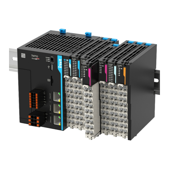
The TM700 series programmable controllers are a new generation of medium PLC products independently developed by INVT, which support EtherCAT bus, Ethernet bus, RS485, on-board high-speed I/O interfaces, and up to 16 local expansion modules. Additionally, functions such as CANopen/4G can be expanded through extension cards. -
Page 3: Table Of Contents
TM700 series programmable controller Contents Contents 1 Safety precautions ..........................1 1.1 Safety declaration ..............................1 1.2 Safety level definition ............................1 1.3 Personnel requirements ............................1 1.4 Safety guidelines ..............................1 2 Product overview ............................ 3 2.1 Product nameplate and model ..........................3 2.2 Interface description ............................ -
Page 4: Safety Precautions
TM700 series programmable controller Safety precautions 1 Safety precautions 1.1 Safety declaration Read this manual carefully and follow all the safety precautions before moving, installing, wiring, commissioning and running the programmable controller. Otherwise, equipment damage or physical injury or death may be caused. We shall not be liable or responsible for any equipment damage or physical injury or death caused due to failure to follow the safety precautions. - Page 5 TM700 series programmable controller Safety precautions Wiring Fully understand the interface types, specifications, and related requirements before wiring. Otherwise, incorrect wiring cause abnormal running. Before power-on for running, ensure that each module terminal cover is properly installed in place after the installation and wiring are completed. This prevents a live terminal from being touched.
-
Page 6: Product Overview
TM700 series programmable controller Product overview 2 Product overview 2.1 Product nameplate and model Product Product nameplate Product model Nameplate parameters position TM753 Programmable Logic Controller Power Input: 24V DC Output: 24V DC 0.5A RES LOAD QR code S/N code SN: I06228000058 LOAD Wiring... - Page 7 TM700 series programmable controller Product overview Interface Port type Definition Description sign Turn to RUN: The user program Start/stop DIP User program running runs. switch state Turn to STOP: The user program STOP stops. On: The power supply is normal. Power state display Off: power...
-
Page 8: Product Specifications
TM700 series programmable controller Product overview Interface Port type Definition Description sign Default IP: 192.168.1.10 Green indicator on: It indicates that link been established successfully. Green indicator off: It indicates Ethernet communication Ethernet port Ethernet1 that the link is not established. interface Yellow indicator... -
Page 9: Di Input Specifications
TM700 series programmable controller Product overview Item TM750 TM751 TM752 TM753 function. Supports Modbus TCP, OPC UA, TCP/UDP, program upload and download, EtherNet bus and firmware upgrade. 1 channel, supporting program upload and download, and firmware Type-C interface upgrade. 8 inputs originally, including 200kHz high-speed inputs 8 outputs originally, including 200kHz high-speed outputs Pulse axis Supports up to 4 channels... -
Page 10: Do Output Specifications
TM700 series programmable controller Product overview 2.3.3 DO output specifications Item Description Output type Transistor output Number of output 8 channels channels Output mode Sink type Output voltage class 24VDC (-10%–+10%) Output load (resistance) 0.5A/point, 2A/8 points output load (inductance) 7.2W/point, 24W/8 points Hardware response time ≤2μs Load current Load current ≥... -
Page 11: Rs485 Specifications
TM700 series programmable controller Product overview 2.3.4 RS485 specifications Item Description Supported channels 2 channels Hardware interface In-line terminal (2×6Pin terminal) Isolation method Integrated chip capacitive isolation Built-in 120Ω terminal resistor, selectable by shorting R1 and R2 on the Terminal resistor 2×6 PIN in-line terminal. -
Page 12: Mechanical Installation
TM700 series programmable controller Mechanical installation 3 Mechanical installation 3.1 Installation environment requirements When installing this product on a DIN rail, full consideration should be given to operability, maintainability, and environmental resistance before installation. Item Specification IP class IP20 Level 2: Generally there is only non-conductive pollution, but you shall consider Pollution level transient conductivity accidentally caused by condensation. - Page 13 TM700 series programmable controller Mechanical installation 3.2.1.2 Installation between the master and the module Align the module with the connection rail with the master sliding rail, and push it inward until the module engages with the DIN rail (there is a noticeable sound of engagement when installed in place). Rail snap-fit Rail DIN rail...
-
Page 14: Disassembly
TM700 series programmable controller Mechanical installation 3.2.1.4 Button battery installation Step 1 Open the button battery cover. Step 2 Push the button battery into the button battery slot in the correct direction, and close the button battery cover. Note: Please note the anode and cathode of the battery. ... - Page 15 TM700 series programmable controller Mechanical installation Clip 3.2.2.3 Button battery disassembly The disassembly steps are as follows: Step 1 Open the button battery cover. (For details, see section 3.2.1.4 Button battery installation). Step 2 Disassemble the I/O terminals (For details, see section 3.2.2.2 I/O terminal disassembly). Step 3 Use a small straight screwdriver to gently push out the button battery, as shown in the following figure.
-
Page 16: Electrical Installation
TM700 series programmable controller Electrical installation 4 Electrical installation 4.1 Cable specifications Table 4-1 Cable dimensions for single cable Applicable cable diameter Tubular cable lug Chinese American standard/mm standard/AWG 0.75 Figure 4-1 Ethernet cable Network port connector crystal head-8P8C-3 forked type 26AWG category 5 shielded twisted-pair cables Signal Signal direction... -
Page 17: Input Terminal Wiring
TM700 series programmable controller Electrical installation Schematic Left signal Left terminal Right terminal Right signal diagram X6 input Y6 output X7 input Y7 output SS input common COM output terminal common terminal Note: The total extension length of high-speed I/O interface expansion cable shall be within 3 meters. ... -
Page 18: Wiring Of Power Supply Terminals
TM700 series programmable controller Electrical installation Note: The flyback diode is needed for external inductive load connection. The wiring diagram is shown as below. Flyback diode Inductive Output load terminal 24VDC 4.3 Wiring of power supply terminals 4.3.1 Terminal definition Right Schematic diagram Left signal... -
Page 19: Ethercat Networking Wiring
When connecting the network cable, hold the crystal head of the cable and insert it into the Ethernet interface (RJ45 interface) until it makes a click sound. When removing the installed network cable, press the tail mechanism of the crystal head and pull out it from the product horizontally. 4.6 Ethernet wiring invt 202408 (V1.0) -
Page 20: Other Description
5 Other description 5.1 Programming tool Programming tool: Invtmatic Studio. How to obtain programming tools: Visit www.invt.com, choose Support > Download, enter a keyword, and click Search. 5.2 Run and stop operations After programs are written to the PLC, perform running and stopping operations as follows. -
Page 21: Appendix A Expansion Card Accessories
TM700 series programmable controller Expansion card accessories Appendix A Expansion card accessories Model Specification Supports the CANopen bus TM-CAN Supports 4G IoT TM-4G 202408 (V1.0) -
Page 22: Appendix B Dimension Drawings
TM700 series programmable controller Dimension drawings Appendix B Dimension drawings Figure B-1 Product dimensions (unit: mm) 80.5 114.18 202408 (V1.0) - Page 23 Website: www.invt.com 6 6 0 0 1 - 0 1 3 8 1...
Need help?
Do you have a question about the TM 700 Series and is the answer not in the manual?
Questions and answers