Table of Contents
Advertisement
Quick Links
IVC3 Series PLC
Quick Reference Manual
Thanks for choosing the programmable logic controllers (PLCs) developed
and produced by INVT Auto-Control Technology (Shenzhen) Co., Ltd. Before
using the PLC, read this manual carefully to understand the product features,
so that you can use the product properly and make full use of its functions.
This manual briefly describes the hardware specification, features, and
application methods of IVC3 series PLCs. It is a quick-start guide for the
design, installation, connection, and maintenance of IVC3 series PLCs. Users
can handily refer to this manual for the required information on site.
Item
Program capacity
64 ksteps
High-speed input
200 kHz
High-speed output
200 kHz
Power-outage
64 kB
memory
The CANopen DS301 protocol (master) supports a
maximum of 31 stations, 64 TxPDOs, and 64
RxPDOs.
The CANopen DS301 protocol (slave) supports 4
CAN
TxPDOs and 4 RxPDOs.
Terminal resistor: Equipped with a built-in DIP switch
Station number setting: Set by using a DIP switch or
program
Supporting master and slave stations
Modbus TCP
IP address setting: Set by using a DIP switch or
program
Communication mode: RS485
Serial
Max. baud rate of PORT1 and PORT2: 115200
communication
Terminal resistor: Equipped with a built-in DIP switch
Standard: USB2.0 Full Speed and MiniB interface
USB
Function:
communication
monitoring, and upgrade of underlying systems
Two-axis linear and arc interpolation (supported by
Interpolation
board software V2.0 or later)
Electronic cam
Supported by board software V2.0 or later
Special extension
Max. total number of special extension modules: 8
module
Customer service center
INVT Auto-Control Technology (Shenzhen) Co., Ltd.
Product quality feedback sheet
User name
User address
Product name and
model
Machine No.
Product appearance or
structure
Product performance
Product package
Product material
Quality in use
Improvement
comments or
suggestions
Gaofa Technology Park, Longjing, Nanshan District, Shenzhen
Postal code: 518055
General-purpose IVC3
Program
upload
and
download,
Telephone
Postal code
Installation date
1 Product introduction
1.1 Model description
Figure 1-1 describes the product model.
I V C 3 - 16 16 M A T
Figure 1-1 Product model description
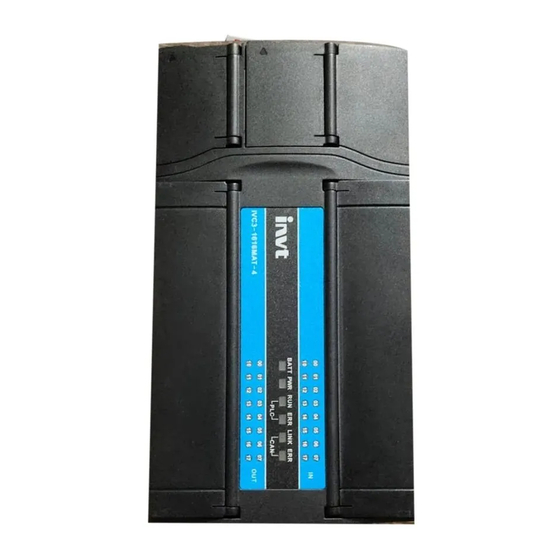
1.2 Appearance and structure
Figure 1-2 shows the appearance and structure of an IVC3 series main
module (using IVC3-1616MAT as an example).
ETH
DIP switch for CAN
communication
Battery mounting
base
USB
DIP switch for
running
PORT0
DIP switch for
terminal resistor
Figure 1-2 Appearance and structure
The bus socket is used to connect extension modules. The mode selection
switch provides three options: ON, TM, and OFF.
1.3 Terminal introduction
The following figures show the terminal arrangement of IVC3-1616MAT.
Input terminals:
S/S
COM
COM
X0
X2
24V
24V
S/S
X1
Output terminals:
.
Y0
Y1
Y2
Y3
Y4
C0
C1
C2
Y5
2 Power supply specifications
Table 2-1 describes the specifications of the built-in power supply of the main
module and those of the power that the main module can supply to extension
modules.
Table 2-1 Power supply specifications
Min.
Item
Unit
value
Input voltage
V AC
85
range
Input current
A
/
5V/GN
mA
/
D
24V/G
mA
/
ND
Rated
output
current
24V/C
mA
/
OM
Output mode (R: Relay output;
T: Transistor output; N: No output)
Power input mode (A: 220 V AC power
input; D: 24 V DC power input; N: No
external power input)
Module type (M: Main module;
E: extension module)
Number of output points
Number of input points
Series number
Identifier of INVT Auto-Control PLCs
Signal input terminal
Input signal state indicator
System operation state indicator
Output signal state indicator
Signal output terminal
X4
X6
X10
X12
X14
X3
X5
X7
X11
X13
X15
Y6
Y7
Y10
Y12
Y14
C3
C4
Y11
Y13
Y15
Typical
Max.
Remarks
value
value
Voltage range for proper
220
264
start and operation
90 V AC input, full-load
/
1.5
output
The capacity is the sum of
1000
/
the internal consumption
of the main module and
650
/
the load of the extension
modules. The maximum
output power is the sum
of the full load of all
600
/
modules, that is, 35 W.
The natural cooling mode
is adopted for the module.
X16
X17
Y16
Y17
1
Advertisement
Table of Contents

Related Manuals for INVT IVC3 Series


Summary of Contents for INVT IVC3 Series
- Page 1 This manual briefly describes the hardware specification, features, and external power input) application methods of IVC3 series PLCs. It is a quick-start guide for the Module type (M: Main module; design, installation, connection, and maintenance of IVC3 series PLCs. Users E: extension module) can handily refer to this manual for the required information on site.
- Page 2 Item Output specification 3 Digital input/output characteristics Total load of the common terminals: Max. Resistive Common terminal of the 0.3 A/1-point group load Common terminal of the 0.8 A/4-point group outpu 3.1 Input characteristics and signal specifications Common terminal of the 1.6 A/8-point group curre Inductive Table 3-1 describes the input characteristics and signal specifications.
- Page 3 Standard CANopen protocol DS301v4.02 that can be applied for master and slave stations, supporting the NMT service, Protocol These steps can also be used to install other PLCs of the IVC3 series by using Error Control protocol, SDO protocol, SYNC, Emergency, and DIN slots.
- Page 4 7. Contact the local dealer or directly contact our company if you have any Figure 5-5 shows the recommended cable preparation mode. questions. Customer Service Center (China) INVT Auto-Control Technology (Shenzhen) Co., Ltd. Address: Gaofa Technology Park, Longjing, Nanshan District, Shenzhen Postal code: 518055 Company website: http://www.invt-control.com/en/index.html Version: V1.2...
Need help?
Do you have a question about the IVC3 Series and is the answer not in the manual?
Questions and answers