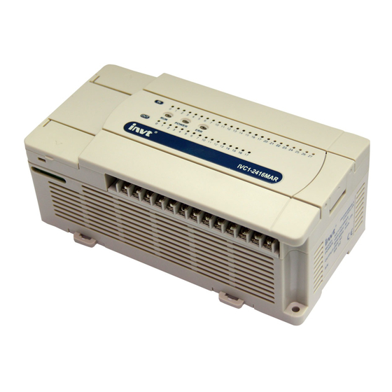
Page 1
V1.2 Revision date March 17, 2015 INVT Auto-Control Technology provides customers with technical support. Users may contact the nearest INVT local sales office, service center or headquarters. INVT Auto-Control Technology Co., Ltd. Copyright. All rights reserved. The content is subject to change without notice.
Page 2
You can jump directly to 错误! 未找到引用源。 错误! 未找到引用源。 and 错误! 未找到引用源。 Application Instructions, which provide complete and detailed explanation for the instructions of INVT IVC series PLC. For sequential function chart (SFC), high-speed I/O, interrupts and communication function, please refer to chapters 7~10. For positioning control, please refer to Appendix 10 Positioning Function Guideline.
Content Chapter 1 Product overview ............................1 Product introduction .............................1 Auto Station programming software ........................5 Communication function ............................7 Documents of IVC series small PLC........................7 Chapter 2 Function description ..........................9 Programming resources and theories........................9 System configuration ............................18 Running mode and state control ......................... 27 System debugging .............................
6.23 Other instructions ............................235 Chapter 7 SFC tutor ..............................236 Introduction to SFC ............................236 Relationship between SFC program and LAD program ..................241 How to program with SFC ..........................242 Points to note in SFC programming ........................243 Examples of SFC programming ........................
Chapter 1 Product overview 1.1 Product introduction The IVC series small PLC, comprising the IVC1, IVC1S, IVC1L mini-scale series and IVC2L, IVC2H small series, is a high performance product suitable for modern industrial control. The IVC series PLC products have integrated structure, built-in high performance microprocessor, operation control system, integrated I/O and extension bus.
Page 6
Programming manual of IVC series small PLC Chapter 1 Product overview Name IVC2H IVC2L IVC1L IVC1 IVC1S output Inductive 220Vac, 80VA current load Light 220Vac, 100W load Resistive Output point: 0.3A/1 point; other: 0.3A/1 point; 0.8A/4 points; 1.6A/8 points load If above 8 points, allow the total current to increase 0.1A for every additional 1 point...
Page 7
Programming manual of IVC series small PLC Chapter 1 Product overview Name IVC2H IVC2L IVC1L IVC1 IVC1S Interpolation interrupt Passed position interrupt Power loss interrupt Running time of 0.065μS 0.09μS 0.2μS 0.3μS 0.3μS basic instruction Support (at least Support (at least...
Page 8
2. For detailed product specifications, installation instructions, operation and maintenance guidelines of IVC2L series PLC, please refer to IVC2L Series PLC User Manual 3. For detailed product specifications, installation instructions, operation and maintenance guidelines of IVC2H series PLC, please refer to IVC2H Series PLC User Manual 4.
Double click it to start the installation, and follow the prompts step by step. You can select an installation path according to your actual need. After the installation, INVT program group will be added to the start menu. An Auto Station shortcut icon will also be added to the desktop. Double click the shortcut icon to run the program.
Page 10
Programming cable You can use the programming cable provided by INVT Auto-Control Technology Co., Ltd. to program and debug the PLC. There are three kinds of cables: one is optically isolated and hot swappable; one is non-isolated and not hot swappable;...
The main module of IVC1/2L series small PLC has two integrated serial ports: PORT0 and PORT1, the main module of IVC1S series small PLC has one integrated serial port: PORT0, and the main module of IVC1L and IVC2H series small PLC has three integrated serial ports: PORT0, PORT1 and PORT2.
Page 12
Programming manual of IVC series small PLC Chapter 1 Product overview IVC1L series Quick Start User Manual of IVC1L Series PLC User Manual of IVC1L Series PLC 1.4.3 Programming manual Programming Manual of IVC Series Small PLC 1.4.4 User manual of programming software User Manual of Auto Station Programming Software 1.4.5 User manual of I/O extension module...
Programming manual of IVC series small PLC Chapter 2 Function description Chapter 2 Function description This chapter introduces the programming resources, theories and system configuration of IVC series PLC as well as how to set PLC running and operation modes. The system commissioning functions and commissioning software are also introduced. 2.1 Programming resources and theories 2.1.1 Programming resources...
Page 14
Programming manual of IVC series small PLC Chapter 2 Function description Name Specification and description X0, X1 Single input: 50kHz. Total frequency (X0~X5): no more than 80kHz High-speed counter X2~X5 Single input: 10kHz High-speed pulse Y0, Y1 100kHz 2 independent outputs (only for transistor outputs) output Digital filtering X0~X7 adopt digital filtering and other terminals adopt hardware filtering...
Page 15
Programming manual of IVC series small PLC Chapter 2 Function description Name Specification and description PTO output interrupt Power loss interrupt Communication 1 asynchronous serial communication port. Port0: RS232 Communication port function Communication Modbus and freeport protocols protocol High-speed X0, X1 Single input: 50kHz.
Page 16
Programming manual of IVC series small PLC Chapter 2 Function description Name Specification and description External input 16 (triggering edge is user configurable, corresponding to the rising&falling edge of terminals interrupt X0~X7) High-speed counter interrupt Internal timer Interrupt interrupt resource Serial port interrupt PTO output...
Page 17
IBM PC or compatible computer is required Note5 mode Note6 software Realtime clock Built-in, standby batteries supply power Table 2-4 IVC2H programming resources Name Specification and description Max. I/O 512 (256 I/256 O) Qty. of extension configuration 8 modules, the sum of special modules is no more than 8...
Page 18
Note 2: Based on the timing precision, T element addresses fall into three categories: IVC1/IVC1S/IVC1L/IVC2L 1) 100ms: T0~T209 2) 10ms: T210~T251 3) 1ms: T252~T255 IVC2H 1) 100ms: T0~T209 2) 10ms: T210~T479 3) 1ms: T480~T511 Note 3: Based on the width and function of count value, C element addresses fall into three categories:...
Page 19
Programming manual of IVC series small PLC Chapter 2 Function description 2.1.2 PLC running mechanism (scan cycle model) IVC series PLC main module runs according to the scan cycle model. The system cyclically executes the following four tasks one by one: user program execution, communication, internal tasks and I/O update.
Page 20
2. If the backup battery fails in IVC2L and IVC2H series PLC, the auxiliary user information will be lost, the annotation for the user program will not be uploaded, and system will report “User information file error”. But the user program will be executed after all.
Page 21
Note 1. The power-off data saving function in IVC2L and IVC2H series PLC relies on the support of the backup battery. If batteries fail, all the saved elements will have uncertain values after power loss. 2. For IVC1 series PLC, the values of its saved elements are stored in the permanent memory.
After setting the system block, you can select PLC-> Compile All to compile the system block file and be ready for download. Saving range Upon power loss, IVC1, IVC1L, IVC2L and IVC2H series PLCs can save the data of elements in the preset saving range to SRAM, so as to use them after the power on.
Page 23
You can change the defaults as you need. By clicking the Clear button on the right will set the corresponding number to zero. For IVC2L and IVC2H series PLC, you can set two groups that form a union. For IVC1 and IVC1L series PLC, you can set only one group.
Page 24
Programming manual of IVC series small PLC Chapter 2 Function description Help Figure 2-4 Setting output table The output table is used to set the PLC output state when the PLC is stopped. The output states include: (1) Disable: When the PLC is stopped, all the outputs will be disabled. (2) Freeze: When the PLC is stopped, all the outputs will be frozen at the last status.
Page 25
IVC1 input filter can be in grouped (divided into X0~X3, X4~X7) and the filter constant is 0, 2, 4, 8, 16, 32 and 64; IVC2H input filter can be grouped (divided into X0~X3, X4~X7) and the filter constant can be continuously set in 0~64ms;...
Page 26
Programming manual of IVC series small PLC Chapter 2 Function description Help Figure 2-7 Setting input point Advanced settings The advanced settings include datablock enabled, element value retained and no battery mode. Help Figure 2-8 Advanced settings 1. Datablock enabled Check the Datablock enabled, and the datablock will be used to initialize the D elements when the PLC changes from STOP to RUN.
Page 27
4. N:N bus protocol N:N bus is an INVT-developed communication protocol that supports N to N communication in a small PLC network. The PLCs in a N:N bus network can automatically exchange part of their D and M elements.
Page 28
Programming manual of IVC series small PLC Chapter 2 Function description Port 0, port1 and port 2 can use N:N bus protocol. Note For the detailed information of communication protocols, see Chapter 10 Using Communication Function. Special module configuration You can set the Module type and Module property in the Special module configuration tab, as shown in 错误!未找到引用...
Page 29
Programming manual of IVC series small PLC Chapter 2 Function description In the dialogue box as shown in 错误!未找到引用源。, you can configure the channel for the special module, including mode (signal features), digital value at zero, upper limit of digital value and average sampling value. Refer to the user manual of the specific special module for the meanings and configuration methods of the various parameters.
Page 30
+ number” is illegal. No keywords shall be used. The keywords include: basic data type, instructions and the operators in the IL programming language. For IVC2H/IVC2L/IVC1 series small PLC, the uploading number the global variables allow shall not exceed 1000/500/140. If beyond the number, the variables can be only saved at local. See Figure 2-16.
2.2.4 Setting BFM for IVC2L and IVC2H series special modules There is no need to set the addresses for IVC2L and IVC2H series special modules, for the main module can detect and address them automatically upon power on. Among the special modules, the analog extension module includes the analog input module and analog output module.
Programming manual of IVC series small PLC Chapter 2 Function description When the PLC is in STOP state, setting the mode selection switch to ON will change the PLC to RUN state. 3. Setting startup mode of input point If the Startup mode of input point is valid in the system block, in STOP state, the designated input points (X0~X17) detected by the system change from OFF to ON, and then the main module enter the RUN state.
Page 33
Programming manual of IVC series small PLC Chapter 2 Function description Uploading You can upload the system block, data block and user program from a PLC to your PC, and save them in a new project. If the battery backed data are valid, the user auxiliary information files will be uploaded together. See Figure 2-18. Figure 2-18 Upload dialog box If you have set a upload password and have not entered it after starting the Auto Station this time, a window asking you to enter the password will pop up before the upload can start.
Page 34
Programming manual of IVC series small PLC Chapter 2 Function description New user program error 新发生的用户程序错误 New user program error 错误记录 Error record 0 SD20 Error record 0 错误记录 SD21 Error record 1 Error record 1 错误记录 Error record 2 SD22 Error record 2 错误记录...
Page 35
Programming manual of IVC series small PLC Chapter 2 Function description Method After making sure that the PC-PLC communication has been set up and the PLC is in RUN state, click Debug->Online edit in the Auto Station main interface to enter the online edit state. In the online edit state, you can edit the main program, subprograms and interrupts as usual.
Page 36
Programming manual of IVC series small PLC Chapter 2 Function description PLC time The PLC time function can be used to display and set PLC present time, as shown in Figure 2-22. Figure 2-22 Setting PLC time Displayed in the PLC time window is the present date and time of PLC. You can adjust the time setting and click the Set time button to validate it.
Page 37
Programming manual of IVC series small PLC Chapter 2 Function description You can see a lock under the forced elements in the LAD, as shown in Figure 2-25: Figure 2-25 Lock signs under forced elements Unforce You can unforce any forced elements when forcing them becomes unnecessary. To unforce an element, select the target element, right click and select Unforce to pop up a dialog box as shown in Figure 2-26.
Page 38
Programming manual of IVC series small PLC Chapter 2 Function description 2.4.7 Generating datablock from RAM This function can continuously read and display the value of up to 500 D registers in the PLC. The results can merge into the datablock or overwrite the original datablock.
Programming manual of IVC series small PLC Chapter 3 Element and data Chapter 3 Element and data This chapter details the description, classification and functions of the elements of IVC series small PLC. 3.1 Element type and function 3.1.1 Element overview The PLC elements are virtual elements configured in PLC system design in order to replace the actual relays in the relay control circuits.
Page 40
The elements of IVC series PLC are classified according to their functions, and are easily accessible. The elements are listed in the following table. Table 3-1 IVC series PLC elements IVC1 series IVC1L series IVC2L series IVC2H series Numbered in 128 I/128 O(input 128 I/128 O(input 256 I/256 O (input 256 I/256 O (input...
Page 41
Programming manual of IVC series small PLC Chapter 3 Element and data 3.1.3 Input and output points Element mnemonic counters. Besides, X0~X7 can also be used for inputting external interrupts, pulse tracking and SPD frequency X (discrete input point) detecting instruction.
Page 42
Programming manual of IVC series small PLC Chapter 3 Element and data 3.1.4 Auxiliary relays Element mnemonic Value assignment 1. Through instructions. Function 2. Write or force during system debugging. The M state elements of discrete type are similar to the Power loss saving transfer relays in the actual electrical control circuits.
Page 43
Programming manual of IVC series small PLC Chapter 3 Element and data The T elements with the timing precision of 1ms are 2. Write or force during system debugging. activated by interrupts, unrelated to the PLC scan cycle. Power loss saving Their action time is the most precise.
Page 44
Programming manual of IVC series small PLC Chapter 3 Element and data 3.1.8 Data register Element mnemonic Note In a double-word D or R element, the higher 16-bit is in D, R the first D or R element; and the lower 16-bit is in the Function second D or R element.
Page 45
Programming manual of IVC series small PLC Chapter 3 Element and data 3.1.10 Special data register SD66~SD68: cycle of timed interrupt. Element mnemonic SD80~SD89: locating instruction parameters. Elements numbered in Function Decimal, starting with 0 The SD elements are closely related to the PLC system Data type function.
Programming manual of IVC series small PLC Chapter 3 Element and data 3.1.13 Local data registe transfer. For details, see 错误!未找到引用源。错误!未 Element mnemonic 找到引用源。 . Elements numbered in Function Decimal, starting with 0 The V elements are local variables and can be used in the Data type main program and subprograms.
Page 47
Indexed addressing mode (Z addressing mode) Concept The IVC2L/IVC2H series PLC provides the Z addressing mode, or indexed addressing mode. You can use the Z elements (indexed addressing register) to get indirect access to the targe elements. Z addressing method...
Programming manual of IVC series small PLC Chapter 3 Element and data 3.2.4 Storing&addressing 32-bit data in D, R and V Elements Storing 32-bit data in D, R and V elements The DINT, DWORD and REAL data are all 32-bit, while the D, R or V elements are only 16-bit. Two consecutive D, R or V elements are needed to store the 32-bit data.
Page 49
Programming manual of IVC series small PLC Chapter 3 Element and data If an instruction uses an operand with unsuitable data type, the instruction will be deemed illegal. For example, instruction “MOV 10 X0” is illegal because operand 2 of the MOV instruction is of signed integer data type, while the X0 element can store only Boolean data.
Programming manual of IVC series small PLC Chapter 4 Programming concepts Chapter 4 Programming concepts This chapter details the programming of IVC series small PLC, including the programming language, program components, data type, addressing mode and annotating function. The programming and usage of subprograms are also introduced, and finally, the general explanation of instructions.
Page 51
Programming manual of IVC series small PLC Chapter 4 Programming concepts Power flow No.1 Power flow No.1 Power flow No.2 Power flow No.3 Three power flows Figure 4-2 Power flow and its driving function 4.1.2 Instruction list (IL) The IL, or the instruction list composed by users, is a text programming language. The user program stored in the PLC main module is actually the instruction list recognizable to the main module.
Programming manual of IVC series small PLC Chapter 4 Programming concepts Figure 4-3 Example of SFC 4.2 Program components The program components include user program, system block and data block. You can change these components by programming. 4.2.1 User program A user program is the program code composed by users.
Programming manual of IVC series small PLC Chapter 4 Programming concepts If the Datablock enabled is checked in the Advanced Settings tab of System block, the D or R elements will be initialized by the data block before the PLC executes the user program. 4.3 Block comment and variable comment 4.3.1 Block comment...
Page 54
Programming manual of IVC series small PLC Chapter 4 Programming concepts A block comment occupies a whole row. You cannot add a block comment to an occupied row, nor can a row occupied by a comment be used for other purposes. 4.3.2 Variable comment You can define variables in the Local variable table and Global variable table.
Note The block comment, global variable table and local variable table can be compiled and downloaded to IVC2L and IVC2H series PLC. To store such information, battery backup is needed. However, although battery failure may cause information loss, comment upload failure and user information file error report, the user program can still run normally.
Page 56
Programming manual of IVC series small PLC Chapter 4 Programming concepts Based on the variable data type, the software will automatically assign a fixed LM or V element address to each SBR variable in sequence. 2. Variable name You can give each SBR variable a name (alias). You can use a variable in the program by quoting its name. 3.
Programming manual of IVC series small PLC Chapter 4 Programming concepts Figure 4-11 Writing SBR_1 Step 3: Write the main program and call the SBR Use the CALL instruction in the main program to call SBR_1. The corresponding main program is as shown below: LD M0 CALL SBR_1 3 2 D0 You can use the parameter transfer relationship table as shown in the following figure to set the parameters transferred to the...
Page 58
Programming manual of IVC series small PLC Chapter 4 Programming concepts Source operands: or S (or S … when there are more than one of them in the same instruction). The instruction reads values from source operands for calculation. ...
M1536~M2047, the actual program steps will be the instruction program steps plus 1. For the contact logic instructions of IVC2H series, when the operands are M1536~M10240, C256~C511, T256~T511 and S0~S4096, the actual program steps will be the instruction program steps plus 1.
Page 60
M1536~M2047, the actual program steps will be the instruction program steps plus 1. For the contact logic instructions of IVC2H series, when the operands are M1536~M10240, C256~C511, T256~T511 and S0~S4096, the actual program steps will be the instruction program steps plus 1.
Page 61
When M0 or M1 is ON, Y0 is ON. current power flow, assign the value to the current power flow. 5.1.6 ORI: NC contact power-flow or LAD: Applicable to IVC1 IVC1S IVC1L IVC2L IVC2H Influenced flag bit IL: ORI (S) Program steps Indexed Operand Type Applicable elements...
Page 62
Programming manual of IVC series small PLC Chapter 5 Basic instructions 5.1.7 OUT: Power-flow output LAD: Applicable to IVC1 IVC1S IVC1L IVC2L IVC2H Influenced flag bit IL: OUT (S) Program steps Indexed Operand Type Applicable elements addressing BOOL Dx.y Operand description...
Page 63
When both M1 and M2 are ON, or both M3 and M4 are ON, Y0 outputs ON. 5.1.10 MPS: Output power-flow input stack LAD: Applicable to IVC1 IVC1S IVC1L IVC2L IVC2H Influenced flag bit IL: MPS Program steps Function description...
Page 64
Pop the power flow output stack, and assign the popped value to the current power flow. 5.1.13 EU: Power flow rising edge detection LAD: Applicable to IVC1 IVC1S IVC1L IVC2L IVC2H Influenced flag bit IL: EU Program steps Function description Example Compare the current power flow status with its previous status.
Page 65
Y3 will output ON status with the width of a scan cycle. 5.1.15 INV: Power-flow block inverse LAD: Applicable to IVC1 IVC1S IVC1L IVC2L IVC2H Influenced flag bit IL: INV Program steps Function description Reverse the current power flow value and then assign to the current power flow.
If D is C element, the corresponding count value will be reset; if D is T element, the corresponding timing value will be reset. 5.1.18 NOP: No operation LAD: Applicable to IVC1 IVC1S IVC1L IVC2L IVC2H Influenced flag bit IL: NOP Program steps Note Function description In LAD program, this instruction cannot directly This instruction does not enable any action.
OUT instruction in the programming. structure will be cleared, Y0=OFF. 5.3 SFC instructions 5.3.1 STL: SFC state load instruction LAD: Applicable to IVC1 IVC1S IVC1L IVC2L IVC2H Influenced flag bit IL: STL(S) Program steps Indexed Operand Type Applicable elements addressing...
Page 68
Programming manual of IVC series small PLC Chapter 5 Basic instructions LAD: Applicable to IVC1 IVC1S IVC1L IVC2L IVC2H Influenced flag bit IL: SET(D) Program steps Indexed Operand Type Applicable elements addressing BOOL Operand description Function description D: Destination operand...
Programming manual of IVC series small PLC Chapter 5 Basic instructions 5.4 Timer instruction 5.4.1 TON: On-delay timing instruction LAD: Applicable to IVC1 IVC1S IVC1L IVC2L IVC2H Influenced flag bit IL: TON (D) (S) Program steps Indexed Operand Type Applicable elements...
Page 70
T1 timing value output is ON. 5.4.4 TMON: Monostable timing instruction Applicable to IVC1 IVC1S IVC1L IVC2L IVC2H LAD: Influenced flag bit IL: TMON (D) (S) Program steps Indexed Operand Type...
OFF. 5.5 Counter instruction 5.5.1 CTU: 16-bit counter counting up instruction LAD: Applicable to IVC1 IVC1S IVC1L IVC2L IVC2H Influenced flag bit IL: CTU (D) (S) Program steps Indexed Operand Type...
Page 72
2. The address of the 16-bit counter C (D) shall be within C0~C199. 5.5.3 DCNT: 32-bit counting instruction LAD: Applicable to IVC1 IVC1S IVC1L IVC2L IVC2H Influenced flag bit IL: DCNT (D) (S) Program steps Indexed Operand Type Applicable elements...
This chapter introduces the application instructions of IVC series small PLC, including the formats, operands, influenced flag bit, functions, examples and time sequence charts of the instructions. 6.1 Program flow control instruction 6.1.1 FOR: Cycle instruction LAD: Applicable to IVC1 IVC1S IVC1L IVC2L IVC2H Influenced flag bit IL: FOR (S) Program steps Indexed Operand Type Applicable elements...
Page 74
To prevent the operation overtime error, use the WDT instruction in a time-consuming loop. 6.1.3 LBL: Jump label definition Applicable to IVC1 IVC1S IVC1L IVC2L IVC2H LAD: Influenced flag bit IL: LBL (S) Program steps...
Page 75
Programming manual of IVC series small PLC Chapter 6 Application instructions 6.1.4 CJ: Conditional jump Applicable to IVC1 IVC1S IVC1L IVC2L IVC2H LAD: Influenced flag bit IL: CJ (S) Program steps Indexed Operand Type Applicable elements addressing INT Constant Operand description...
Page 76
Chapter 6 Application instructions 6.1.6 WDT: User program watchdog reset LAD: Applicable to IVC1 IVC1S IVC1L IVC2L IVC2H Influenced flag bit IL: WDT Program steps Function description When the power flow is valid, the instruction will clear the user program watchdog, and the watchdog will restart timing.
Page 77
Programming manual of IVC series small PLC Chapter 6 Application instructions 6.1.11 CALL: Calling a subprogram LAD: Applicable to IVC1 IVC1S IVC1L IVC2L IVC2H Influenced flag bit Determined by the subprogram IL: CALL (SBR name) (PARAM1) (PARAM2) … Program steps...
Programming manual of IVC series small PLC Chapter 6 Application instructions 6.2 Data transmission instruction 6.2.1 MOV: Move word data transmission instruction LAD: Applicable to IVC1 IVC1S IVC1L IVC2L IVC2H Influenced flag bit IL: MOV (S) (D) Program steps Indexed Operand Type Applicable elements...
Page 79
Programming manual of IVC series small PLC Chapter 6 Application instructions 6.2.3 RMOV: Move floating point number data transmission LAD: Applicable to IVC1 IVC1S IVC1L IVC2L IVC2H Influenced flag bit IL: RMOV (S) (D) Program steps Indexed Operand Type Applicable elements...
Page 80
Programming manual of IVC series small PLC Chapter 6 Application instructions 6.2.5 FMOV: Fill data block instruction LAD: Applicable to IVC1 IVC1S IVC1L IVC2L IVC2H Influenced flag bit IL: FMOV (S1) (D) (S2) Program steps Indexed Operand Type Applicable elements...
Page 81
Programming manual of IVC series small PLC Chapter 6 Application instructions 6.2.7 SWAP: Swap bytes LAD: Applicable to IVC1 IVC1S IVC1L IVC2L IVC2H Influenced flag bit IL: SWAP (D) Program steps Indexed Operand Type Applicable elements addressing KnLM √ Operand description...
Page 82
Programming manual of IVC series small PLC Chapter 6 Application instructions 6.2.9 DXCH: Exchange double word instruction LAD: Applicable to IVC1 IVC1S IVC1L IVC2L IVC2H Influenced flag bit IL: DXCH (D1) (D2) Program steps Indexed Operand Type Applicable elements addressing...
Page 83
Programming manual of IVC series small PLC Chapter 6 Application instructions 6.2.11 FIFO: First-in-first-out instruction LAD: Applicable to IVC1 IVC1S IVC1L IVC2L IVC2H (D1) (D2) FIFO Influenced flag bit FIFO (D1) (D2) IL: FIFO (D1) (D2) (S) Program steps Indexed...
Page 84
Programming manual of IVC series small PLC Chapter 6 Application instructions 6.2.12 LIFO: Last-in-first-out instruction Applicable to IVC1 IVC1S IVC1L IVC2L IVC2H LAD: Influenced flag bit IL: LIFO (D1) (D2) (S) Program steps Indexed Operand Type Applicable elements addressing √...
Page 85
Programming manual of IVC series small PLC Chapter 6 Application instructions 6.2.13 WSFR: Shift right word instruction Applicable to IVC1 IVC1S IVC1L IVC2L IVC2H LAD: Influenced flag bit Zero, carry, borrow IL: WSFR (S1) (D) (S2) (S3) Program steps Indexed...
Page 86
Programming manual of IVC series small PLC Chapter 6 Application instructions 6.2.14 WSFL: Shift left word instruction LAD: Applicable to IVC1 IVC1S IVC1L IVC2L IVC2H Influenced flag bit Zero, carry, borrow IL: WSFL (S1) (D) (S2) (S3) Program steps Indexed...
Programming manual of IVC series small PLC Chapter 6 Application instructions 6.3 Integer math instruction 6.3.1 ADD: Add integer instruction LAD: Applicable to IVC1 IVC1S IVC1L IVC2L IVC2H Influenced flag bit Zero, carry, borrow IL: ADD (S1) (S2) (D) Program steps Indexed Operand Type...
Page 88
Programming manual of IVC series small PLC Chapter 6 Application instructions 6.3.3 MUL: Multiply integer instruction Applicable to IVC1 IVC1S IVC1L IVC2L IVC2H LAD: Influenced flag bit IL: MUL (S1) (S2) (D) Program steps Indexed Operand Type Applicable elements addressing...
Page 89
Programming manual of IVC series small PLC Chapter 6 Application instructions 6.3.5 SQT: Square root integer instructions LAD: Applicable to IVC1 IVC1S IVC1L IVC2L IVC2H Influenced flag bit Zero, carry, borrow IL: SQT (S) Program steps Indexed Operand Type Applicable elements...
Page 90
Programming manual of IVC series small PLC Chapter 6 Application instructions 6.3.7 DEC: Decrement integer instruction LAD: Applicable to IVC1 IVC1S IVC1L IVC2L IVC2H Influenced flag bit IL: DEC (D) Program steps Indexed Operand Type Applicable elements addressing KnLM √...
Page 91
Programming manual of IVC series small PLC Chapter 6 Application instructions 6.3.10 DADD: Add double integer instruction LAD: Applicable to IVC1 IVC1S IVC1L IVC2L IVC2H Influenced flag bit Zero, carry, borrow IL: DADD (S1) (S2) (D) Program steps Indexed Operand Type...
Page 92
Programming manual of IVC series small PLC Chapter 6 Application instructions 6.3.12 DMUL: Multiply double integer instruction LAD: Applicable to IVC1 IVC1S IVC1L IVC2L IVC2H Influenced flag bit IL: DMUL (S1) (S2) (D) Program steps Indexed Operand Type Applicable elements...
Page 93
Programming manual of IVC series small PLC Chapter 6 Application instructions 6.3.14 DSQT: Square root double integer instruction LAD: Applicable to IVC1 IVC1S IVC1L IVC2L IVC2H Influenced flag bit IL: DSQT (S) Program steps Indexed Operand Type Applicable elements addressing...
Page 94
Programming manual of IVC series small PLC Chapter 6 Application instructions 6.3.16 DDEC: Decrement double integer instruction LAD: Applicable to IVC1 IVC1S IVC1L IVC2L IVC2H Influenced flag bit IL: DDEC (D) Program steps Indexed Operand Type Applicable elements addressing DINT KnLM √...
Page 95
Programming manual of IVC series small PLC Chapter 6 Application instructions 6.3.18 DNEG: Negative double integer instruction LAD: Applicable to IVC1 IVC1S IVC1L IVC2L IVC2H Influenced flag bit Zero, carry, borrow IL: DNEG (S) Program steps Indexed Operand Type Applicable elements...
Programming manual of IVC series small PLC Chapter 6 Application instructions 6.3.20 DSUM: Sum double integer instruction Applicable to IVC1 IVC1S IVC1L IVC2L IVC2H LAD: Influenced flag bit Zero, carry, borrow IL: DSUM (S1) (S2) (D) Program steps Indexed Operand Type...
Page 97
(SM181) will be set. When the operation result is 0, the zero flag bit (SM180) will be set. 6.4.3 RMUL: Multiply floating point number instruction Applicable to IVC1 IVC1S IVC1L IVC2L IVC2H LAD: Influenced flag bit Zero, carry, borrow IL: RMUL (S1) (S2) (D)
Page 98
Programming manual of IVC series small PLC Chapter 6 Application instructions 6.4.4 RDIV: Divide floating point number instruction LAD: Applicable to IVC1 IVC1S IVC1L IVC2L IVC2H Influenced flag bit Zero, carry, borrow IL: RDIV (S1) (S2) (D) Program steps Indexed...
Page 99
Programming manual of IVC series small PLC Chapter 6 Application instructions 6.4.6 RVABS: Floating point number absolute value instruction LAD: Applicable to IVC1 IVC1S IVC1L IVC2L IVC2H Influenced flag bit IL: RVABS (S) Program steps Indexed Operand Type Applicable elements...
Page 100
Programming manual of IVC series small PLC Chapter 6 Application instructions 6.4.9 COS: Floating point number COS instruction LAD: Applicable to IVC1 IVC1L IVC2L IVC2H Influenced flag bit Zero, carry, borrow IL: COS (S) Program steps Indexed Operand Type Applicable elements...
Page 101
Programming manual of IVC series small PLC Chapter 6 Application instructions 6.4.11 POWER: Floating point number exponentiation instruction LAD: Applicable to IVC1 IVC1L IVC2L IVC2H Influenced flag bit Zero, carry, borrow IL: POWER (S1) (S2) (D) Program steps Indexed Operand Type...
Page 102
Programming manual of IVC series small PLC Chapter 6 Application instructions 6.4.13 EXP: Floating point number EXP instruction LAD: Applicable to IVC1 IVC1L IVC2L IVC2H Influenced flag bit Zero, carry, borrow IL: EXP (S) Program steps Indexed Operand Type Applicable elements...
Page 103
2. When the operation result (D) is 0, 0.523599 to (D10, D11). the zero flag bit (SM180) will be set. 6.4.16 ACOS: Floating point number ACOS instruction Applicable to IVC2H LAD: Influenced flag bit Zero, carry, borrow IL: ACOS (S)
Page 104
Programming manual of IVC series small PLC Chapter 6 Application instructions 6.4.17 ATAN: Floating point number ATAN instruction Applicable to IVC2H LAD: Influenced flag bit Zero, carry, borrow IL: ATAN (S) Program steps Indexed Operand Type Applicable elements addressing REAL Constant √...
S to the angle, and assign the result to D. 6.5 Data converting instruction 6.5.1 DTI: Double integer to integer instruction LAD: Applicable to IVC1 IVC1S IVC1L IVC2L IVC2H Influenced flag bit Zero, carry, borrow IL: DTI (S) (D) Program steps Indexed Operand Type...
Page 106
Programming manual of IVC series small PLC Chapter 6 Application instructions 6.5.2 ITD: Integer to double integer instruction LAD: Applicable to IVC1 IVC1S IVC1L IVC2L IVC2H Influenced flag bit Zero, carry, borrow IL: ITD (S) (D) Program steps Indexed Operand Type...
Page 107
Programming manual of IVC series small PLC Chapter 6 Application instructions 6.5.5 INT: Floating point number to integer instruction LAD: Applicable to IVC1 IVC1L IVC2L IVC2H Influenced flag bit Zero, carry, borrow IL: INT (S) (D) Program steps Indexed Operand Type...
Page 108
Programming manual of IVC series small PLC Chapter 6 Application instructions 6.5.7 BCD: Word to 16-bit BCD instruction Applicable to IVC1 IVC1S IVC1L IVC2L IVC2H LAD: Influenced flag bit Zero, carry, borrow IL: BCD (S) (D) Program steps Indexed Operand Type...
Page 109
Programming manual of IVC series small PLC Chapter 6 Application instructions 6.5.9 BIN: 16-bit BCD to word instruction LAD: Applicable to IVC1 IVC1S IVC1L IVC2L IVC2H Influenced flag bit Zero, carry, borrow IL: BIN (S) (D) Program steps Indexed Operand...
Page 110
Programming manual of IVC series small PLC Chapter 6 Application instructions 6.5.11 GRY: Word to 16-bit Gray code instruction Applicable to IVC1 IVC1S IVC1L IVC2L IVC2H LAD: Influenced flag bit Zero, carry, borrow IL: GRY (S) (D) Program steps Indexed...
Page 111
Programming manual of IVC series small PLC Chapter 6 Application instructions 6.5.14 DGBIN: 32-bit Gray code to double word instruction Applicable to IVC1 IVC1S IVC1L IVC2L IVC2H LAD: Influenced flag bit Zero, carry, borrow IL: DGBIN (S) (D) Program steps...
Page 112
Programming manual of IVC series small PLC Chapter 6 Application instructions 6.5.16 ASC: ASCII code conversion instruction LAD: Applicable to IVC1 IVC1S IVC1L IVC2L IVC2H Influenced flag bit Zero, carry, borrow IL: ASC (S1~S8) (D) Program steps Indexed Operand Type...
Page 113
If SM186=OFF, the execution result is: D20=0x3839, D21=0x3637. 6.5.18 ATI: ASCII code-hexadecimal number conversion instruction Applicable to IVC1 IVC1S IVC1L IVC2L IVC2H LAD: Influenced flag bit Zero, carry, borrow IL: ATI (S1) (D) (S2) Program steps...
Page 114
>32767, the result is 32767; <-32768, the D205=-154 result is -32768. Example 6.5.20 RLCNV: Floating point engineering conversion instruction LAD: Applicable to IVC2L IVC2H Influenced flag bit Zero, carry, borrow IL: RLCNV (S1)(S2)(D)(S3) Program steps Indexed Operand Type Applicable elements...
Page 115
Programming manual of IVC series small PLC Chapter 6 Application instructions Example Operand description S1: starting address of source operand under conversion S2: starting address of conversion table D: starting address of storing conversion result S3: number of data under conversion; 1≤S3≤64 Function description When the analog input module is used to read external analog signals, the instruction can convert the original...
Programming manual of IVC series small PLC Chapter 6 Application instructions 6.6 Word logic operation 6.6.1 WAND: AND word instruction Applicable to IVC1 IVC1S IVC1L IVC2L IVC2H LAD: Influenced flag bit Program steps IL: WAND (S1) (S2) (D) Indexed Operand...
Page 117
D. 2#0010010110111101 (9661) is assigned to D10. 6.6.4 WINV: NOT word instruction Applicable to IVC1 IVC1S IVC1L IVC2L IVC2H LAD: Influenced flag bit Program steps IL: WINV (S) (D) Indexed Operand Type Applicable elements addressing...
Page 118
OR operation, and the result 2#10111010101111111111011101110011 (3133142899) is and S2 will conduct logic OR assigned to (D10, D11). 6.6.7 DWXOR: Exclusive-OR double word instruction Applicable to IVC1 IVC1S IVC1L IVC2L IVC2H LAD: Influenced flag bit Program steps IL: DWXOR (S1) (S2) (D) Indexed...
Programming manual of IVC series small PLC Chapter 6 Application instructions 6.7 Shift/Rotate instruction 6.7.1 ROR: 16-bit circular shift right instruction IVC1 IVC1S IVC1L IVC2L IVC2H Applicable to LAD: Influenced flag bit Carry flag SM181 IL: ROR (S1) (D) (S2)
Page 120
When M0 is ON, D0 2#1100110110010101 (52629) rotates leftward for 15 bits, and the result 2#1110011011001010 (59082) is assigned to D10. The final bit will be stored in the carry flag bit. SM181 is OFF. 6.7.3 RCR: 16-bit carry circular shift right instruction IVC1 IVC1S IVC1L IVC2L IVC2H Applicable to LAD: Influenced flag bit...
Page 121
4. rotate leftward for 16-bits, and the result 2#1110011011001010 (59082) is assigned to D10. SM181=ON. 6.7.5 DROR: 32-bit circular shift right instruction IVC1 IVC1S IVC1L IVC2L IVC2H Applicable to LAD: Influenced flag bit Carry flag SM181...
Page 122
2. Please refer to the ROL instruction illustration. SM181. 6.7.7 DRCR: 32-bit carry circular shift right instruction IVC1 IVC1S IVC1L IVC2L IVC2H Applicable to LAD: Influenced flag bit Carry flag SM181 IL: DRCR (S1)
Page 123
Programming manual of IVC series small PLC Chapter 6 Application instructions 6.7.8 DRCL: 32-bit carry circular shift left instruction IVC1 IVC1S IVC1L IVC2L IVC2H Applicable to LAD: Influenced flag bit Carry flag SM181 IL: DRCL (S1) (D) (S2) Program steps...
Page 124
Programming manual of IVC series small PLC Chapter 6 Application instructions 6.7.10 SHL: 16-bit shift left instruction IVC1 IVC1S IVC1L IVC2L IVC2H Applicable to LAD: Influenced flag bit IL: SHL (S1) (D) (S2) Program steps Indexed Operand Type Applicable elements...
Page 125
Programming manual of IVC series small PLC Chapter 6 Application instructions 6.7.12 DSHL: 32-bit shift left instruction IVC1 IVC1S IVC1L IVC2L IVC2H Applicable to LAD: Influenced flag bit IL: DSHL (S1) (D) (S2) Program steps Indexed Operand Type Applicable elements...
Page 126
M12=1, M13=0, M14=0, m15=0, m16=0, m17=1, m18=0, m19=1. M13=0, M14=0, M15=1, M16=0, M17=0, M18=0, M19=1. 6.7.14 SFTL: Shift left byte instruction Applicable to IVC2L IVC1 IVC1S IVC2H LAD: Influenced flag bit IL: SFTL (S1) (D) (S2) (S3) Program steps Indexed Operand...
Programming manual of IVC series small PLC Chapter 6 Application instructions 6.8 External equipment instruction 6.8.1 FROM: Read word from special module buffer register instruction IVC2H IVC2L Applicable to LAD: Influenced flag bit IL: FROM (S1) (S2) (D) (S3) Program steps...
Page 128
Programming manual of IVC series small PLC Chapter 6 Application instructions 6.8.2 DFROM: Read double word from special module buffer register instruction LAD: Applicable to IVC2L IVC2H Influenced flag bit IL: DFROM (S1) (S2) (D) (S3) Program steps Indexed Operand Type...
Page 129
Programming manual of IVC series small PLC Chapter 6 Application instructions 6.8.3 TO: Write word to special module buffer register instruction LAD: Applicable to IVC2L IVC2H Influenced flag bit IL: TO (S1) (S2) (S3) (S4) Program steps Indexed Operand Type...
Page 130
Programming manual of IVC series small PLC Chapter 6 Application instructions 6.8.4 DTO: Write double word to special module buffer register instruction LAD: Applicable to IVC2L IVC2H Influenced flag bit IL: DTO (S1) (S2) (S3) (S4) Program steps Indexed Operand Type...
Page 131
Programming manual of IVC series small PLC Chapter 6 Application instructions 6.8.6 REFF: Set input filtering constant instruction LAD: Applicable to IVC1 IVC1S IVC1L IVC2L IVC2H Influenced flag bit IL: REFF (S) Program steps Indexed Operand Type Applicable elements addressing KnLM KnSM √...
Page 132
Programming manual of IVC series small PLC Chapter 6 Application instructions 6.8.8 EROMWR: EEPROM write instruction Applicable to IVC2L IVC1 IVC2H LAD: Influenced flag bit IL: EROMWR (S1) (S2) Program steps Indexed Operand Type Applicable elements addressing WORD Constant KnX KnY KnLM KnSM √...
Page 133
Programming manual of IVC series small PLC Chapter 6 Application instructions 6.8.9 PR: Print instruction LAD: Applicable to IVC2L IVC2H PR (S) (D) Influenced flag bit IL: PR (S) (D) Program steps Indexed Operand Type Applicable elements addressing WORD √...
Page 134
Programming manual of IVC series small PLC Chapter 6 Application instructions 6.8.10 TKY: Numeric key input instruction LAD: Applicable to IVC2H Influenced flag bit TKY (S) (D1) (D2) Program steps Indexed Operand Type Applicable elements addressing BOOL KnY KnM KnLM √...
Programming manual of IVC series small PLC Chapter 6 Application instructions 6.9 Real-time clock instruction 6.9.1 TRD: Read real-time clock instruction LAD: Applicable to IVC1 IVC1L IVC2L IVC2H Influenced flag bit IL: TRD (D) Program steps Indexed Operand Type Applicable elements...
Page 136
Programming manual of IVC series small PLC Chapter 6 Application instructions 6.9.2 TWR: Write real-time clock instruction LAD: Applicable to IVC1 IVC1L IVC2L IVC2H Influenced flag bit IL: TWR (S) Program steps Indexed Operand Type Applicable elements addressing WORD √...
Page 137
Programming manual of IVC series small PLC Chapter 6 Application instructions 6.9.3 TADD: Add clock instruction Applicable to IVC1 IVC1L IVC2L IVC2H LAD: Influenced flag bit Zero flag SM180 Carry flag SM181 IL: TADD (S1) (S2) (D) Program steps Indexed...
Page 138
Programming manual of IVC series small PLC Chapter 6 Application instructions 6.9.4 TSUB: Subtract clock instruction Applicable to IVC1 IVC1L IVC2L IVC2H LAD: Zero flag SM180, Influenced flag bit borrow flag SM182 IL: TADD (S1) (S2) (D) Program steps Indexed...
Page 139
Programming manual of IVC series small PLC Chapter 6 Application instructions 6.9.5 HOUR: Timing list instruction LAD: Applicable to IVC1 IVC1L IVC2L IVC2H Influenced flag bit IL: HOUR (S) (D1) (D2) Program steps Indexed Operand Type Applicable elements addressing Constant KnX KnY KnLM KnSM √...
Page 140
Programming manual of IVC series small PLC Chapter 6 Application instructions 6.9.6 DCMP: Compare date (=、<、>、<>、>=、<=) instruction LAD: Applicable to IVC1 IVC1L IVC2L IVC2H Influenced flag bit DCMP= (S1) (S2) DCMP< (S1) (S2) DCMP> (S1) (S2) Program steps DCMP<> (S1) (S2) DCMP>=...
Page 141
Programming manual of IVC series small PLC Chapter 6 Application instructions 6.9.7 TCMP: Compare time (=、<、>、<>、>=、<=) instruction LAD: Applicable to IVC1 IVC1L IVC2L IVC2H Influenced flag bit TCMP= (S1) (S2) TCMP< (S1) (S2) TCMP> (S1) (S2) Program steps TCMP<> (S1) (S2) TCMP>=...
Page 142
Programming manual of IVC series small PLC Chapter 6 Application instructions 6.9.8 HTOS: Time (hour, minute and second) to second instruction LAD: Applicable to IVC2H Influenced flag bit Program HTOS (S) steps Indexed Operand Type Applicable elements addressing WORD √...
Programming manual of IVC series small PLC Chapter 6 Application instructions 6.10 High-speed I/O instruction 6.10.1 HCNT: High-speed counter drive instruction LAD: Applicable to IVC1 IVC1S IVC1L IVC2L IVC2H Influenced flag bit IL: HCNT (D) (S) Program steps Indexed Operand Type...
Page 144
Programming manual of IVC series small PLC Chapter 6 Application instructions 6.10.2 DHSCS: High-speed counting compare set instruction LAD: Applicable to IVC1 IVC1S IVC1L IVC2L IVC2H Influenced flag bit IL: DHSCS (S1) (S2 ) (D) Program steps Indexed Operand Type...
Page 145
Programming manual of IVC series small PLC Chapter 6 Application instructions 6.10.3 DHSCI: High-speed counting interrupt trigger instruction LAD: Applicable to IVC1 IVC1S IVC1L IVC2L IVC2H Influenced flag bit IL: DHSCI (S1) (S2) (S3) Program steps Indexed Operand Type Applicable elements...
Page 146
Programming manual of IVC series small PLC Chapter 6 Application instructions 6.10.4 DHSPI: High-speed output absolute position compare interrupt trigger instruction LAD: Applicable to IVC2H Influenced flag bit IL: DHSPI (S1) (S2) (S3) Program steps Indexed Operand Type Applicable elements...
Page 147
Programming manual of IVC series small PLC Chapter 6 Application instructions 6.10.5 DHSCR: High-speed counting compare reset instruction Applicable to IVC1 IVC1S IVC1L IVC2L IVC2H LAD: Influenced flag bit IL: DHSCR (S1) (S2) (D) Program steps Indexed Operand Type Applicable elements...
Page 148
Programming manual of IVC series small PLC Chapter 6 Application instructions 6.10.6 DHSZ: High-speed counting zone compare instruction Applicable to IVC1 IVC1S IVC1L IVC2L IVC2H LAD: Influenced flag bit IL: DHSZ (S1) (S2) (S3) (D) Program steps Indexed Operand Type...
Page 149
Programming manual of IVC series small PLC Chapter 6 Application instructions 6.10.7 DHST: High-speed counting table compare instruction LAD: Applicable to IVC1 IVC1S IVC1L IVC2L IVC2H Influenced flag bit IL: DHST (S1) (S2) (S3) Program steps Indexed Operand Type Applicable elements...
Page 151
Programming manual of IVC series small PLC Chapter 6 Application instructions 6.10.8 DHSP: High-speed counting table compare pulse output instruction Applicable to IVC1 IVC1S IVC1L IVC2L IVC2H LAD: Influenced flag bit IL: DHSP (S1) (S2) (S3) Program steps Indexed Operand Type...
Page 152
6. When M0 and X6 are both ON, if X2 is ON, C244 will be cleared, and the C244 contact will be reset. 6.10.9 SPD: Pulse detection instruction Applicable to IVC1 IVC1S IVC1L IVC2L IVC2H LAD: Influenced flag bit IL: SPD (S1) (S2) (D)
Page 153
For details, see 错误!未找到引用源。错误!未找到引用源。 . 2. For IVC1 and IVC2L, the SPD instruction supports input 1000 points X0~X5. For IVC2H, the SPD instruction supports input D12: elapsed time points X0~X7. 3. Maximum pulse input frequency: 10kHz. Detection may Input X0 be faulty when frequency is higher than 10kHz.
Page 154
When M0 is OFF, D: high-speed pulse output point. Range: IVC1, IVC2L: Y0, Y1; there will be no output. IVC1L: Y0,Y1,Y2,Y3; IVC2H: Y0, Y2, Y4, Y5, Y6, Y7. 2. The duty cycle of the pulses is 50%. The output is Function description...
Page 155
Y007 high-speed pulse output monitor (ON: busy, OFF: ready) Address Action and function SD50 PLSY accumulated output Y0 total pulse number (MSB) (IVC1L, IVC2L, IVC2H) SD51 PLSY accumulated output Y0 total pulse number (LSB) (IVC1L, IVC2L, IVC2H) SD52 PLSY accumulated output Y1 total pulse number (MSB) (IVC1L, IVC2L)
Page 156
D: high-speed pulse output point. Range: IVC1, IVC2L: Y0, breaks. In that case, the system will report operand illegal, Y1; IVC1L: Y0, Y1, Y2, Y3; IVC2H: Y0, Y2, Y4, Y5, Y6, Y7. and the high-speed pulse output will be based on the default 10Hz or 20,000Hz.
Page 157
Y007 high-speed pulse output monitor (ON: busy, OFF: ready) Address Action and function SD50 PLSY accumulated output Y0 total pulse number (MSB) (IVC1L, IVC2L, IVC2H) SD51 PLSY accumulated output Y0 total pulse number (LSB) (IVC1L, IVC2L, IVC2H) SD52 PLSY accumulated output Y1 total pulse number (MSB) (IVC1L, IVC2L)
Page 158
SD55 PLSY accumulated output Y1, Y0 total pulse number (LSB) ( IVC2L) SD160 PLSY accumulated output Y2 total pulse number (MSB) (IVC1L, IVC2H) SD161 PLSY accumulated output Y2 total pulse number (LSB) (IVC1L, IVC2H) SD162 PLSY accumulated output Y3 total pulse number (MSB) (IVC1L)
Page 159
Programming manual of IVC series small PLC Chapter 6 Application instructions can control ON or OFF of the PG, and set frequency & pulse number. 2000 2. There is no output when the section number is 0. 2) When the speed of step N is smaller than that of step N-1, 3.
Page 160
Current position of Y1 output locating instruction (MSB) SD83 Current position of Y1 output locating instruction (LSB) SD200 Current position of Y0 output locating instruction (MSB) (IVC2L,IVC2H) SD201 Current position of Y0 output locating instruction (LSB) (IVC2L,IVC2H) SD210 Current position of Y1 output locating instruction (MSB)
Page 161
S2: maximum frequency (Hz). Range: 10~20000 (Hz). When occupied. S2 is outside this range, the system will report instruction D: pulse output point. Range: IVC1, IVC2L: Y0, Y1; IVC2H: operand error, output no pulse, and no hardware resources Y0, Y2, Y4, Y5, Y6, Y7.
Page 162
Programming manual of IVC series small PLC Chapter 6 Application instructions 4. Use the transistor output. During the high-speed pulse 1. When M0 is ON, Y0 and Y1 output 10000 pulses output, the output current must comply with the related respectively at set frequencies.
Page 163
Current position of Y1 output locating instruction (MSB) SD83 Current position of Y1 output locating instruction (LSB) SD200 Current position of Y0 output locating instruction (MSB) (IVC2L,IVC2H) SD201 Current position of Y0 output locating instruction (LSB) (IVC2L,IVC2H) SD210 Current position of Y1 output locating instruction (MSB)
Page 165
Programming manual of IVC series small PLC Chapter 6 Application instructions √ √ √ √ BIT0 process value (positive change) overflows Operand description Bit1 process value (negative change) overflows D: calculation result output after the program is executed (MV) Bit2 output value (positive change) overflows S1: preset value (SV) Bit3 output value (negative change) overflows S2: current value (PV)
Page 166
Programming manual of IVC series small PLC Chapter 6 Application instructions Input change Output change Positive change Positive change Sampling times Sampling times Negative change Negative change Alarm flag Alarm flag S3+19 S3+19 bit 0 bit 2 S3+19 S3+19 bit 1 bit 3 9.Basic PID equations: Direction...
Page 167
Programming manual of IVC series small PLC Chapter 6 Application instructions //PID instruction execution //User-controlled PID calculation program FROM D501 //Input current measured value (users can input measured values //according to the actual situation) D500 D501 D510 D502 //PID instruction: PID S1 S2 S3 D D502 //PID calculation result is fed back to the controlled system (users can //handle the PID calculation result according to the actual situation)
Page 168
Programming manual of IVC series small PLC Chapter 6 Application instructions 6.11.2 RAMP: Ramp wave signal output instruction Applicable to IVC2L IVC1S IVC1L IVC1 IVC2H LAD: Influenced flag bit IL: RAMP (S1) (S2) (D1) (S3) (D2) Program steps Indexed Operand Type...
Page 169
1. When X0 is ON, D10 (in the first cycle, D10=D0=0) will data into analog waveform. increase by 2 (2000/1000) in every scan cycle. When D10= 6.11.3 HACKLE: Hackle wave signal output instruction Applicable to IVC2L IVC1S IVC1L IVC1 IVC2H LAD: Influenced flag bit IL: HACKLE (S1) (S2) (D1)
Page 170
2. You can use an external special module to convert the data into analog waveform. 6.11.4 TRIANGLE: Triangle wave signal output instruction Applicable to IVC2L IVC1S IVC1L IVC1 IVC2H LAD: Influenced flag bit IL: TRIANGLE (S1) (S2) (D1) (S3)
Page 171
The LAD of the preceding instruction is shown in the following figure: 6.11.5 ABSD: Absolute drum control instruction LAD: Applicable to IVC2L IVC2H ABSD (S1) (S2) (D) (S3) Influenced flag bit Zero, carry, borrow IL: ABSD (S1) (S2) (D) (S3) Program steps...
Page 172
M0 is power flow input, X1 is the rotatry angle signal of 1 pulse per degree 6.11.6 DABSD: Double word absolute drum control instruction LAD: Applicable to IVC2L IVC2H Influenced flag bit Zero, carry, borrow IL: DABSD (S1) (S2) (D) (S3) Program steps...
Programming manual of IVC series small PLC Chapter 6 Application instructions 6.11.7 ALT: Alternate output instruction LAD: Applicable to IVC2L IVC2H IVC1L (D) Influenced flag bit Zero, carry, borrow IL: ALT (D) Program steps Indexed Operand Type Applicable elements addressing...
Page 174
S1: designated communication channel (IVC1,IVC2L: Modbus protocol. channel 1; IVC1L,IVC2H: channen1 and channel 2) 2. After the inverter receives the data, it will conduct CRC check, address check and instruction check and set the S2: inverter address.
Page 175
LD M1 S1: designated communication channel (IVC1,IVC2L: IVREV 1 1 channel 1; IVC1L,IVC2H: channen1 and channel 2) 1. Set the serial port 1, inverter address #1, and control the S2: inverter address. Broadcast mode. Broadcast address: inverter reverse running through communication in the 00.
Page 176
LD M1 S1: designated communication channel (IVC1,IVC2L: IVDREV 1 1 channel 1; IVC1L,IVC2H: channen1 and channel 2) 1. Set the serial port 1 and inverter address #1, and control S2: inverter address. Broadcast mode. Broadcast address: the inverter jogging reverse running through communication 00.
Page 177
S1: designated communication channel (IVC1,IVC2L: 1. Set the serial port 1, inverter address #1, and the running channel 1; IVC1L,IVC2H: channen1 and channel 2) frequency of the inverter 50Hz, and control the running S2: inverter address. Broadcast mode. Broadcast address: frequency of the inverter through communication in the 00.
Page 178
WORD √ Example Operand description S1: designated communication channel (IVC1,IVC2L: channel 1; IVC1L,IVC2H: channen1 and channel 2) LD M1 S2: inverter address. Broadcast mode. Broadcast address: IVRDST 1 1 1 D0 00. Slave address range: 1~247. 1. Set the serial port 1, inverter address#1, read status...
Page 179
(SM135) after special register SD139. 6.12.11 XMT: Free port sending instruction Applicable to IVC2L IVC1 IVC1S IVC2H IVC1L LAD: Influenced flag bit IL: XMT (S1) (S2) (S3) Program steps Indexed Operand Type Applicable elements...
Page 180
4. When the sending is completed, set the sending sending the data. completed flag (SM122). 6.12.12 RCV: Free port receiving instruction LAD: Applicable to IVC2L IVC1 IVC1S IVC2H IVC1L Influenced flag bit IL: RCV (S1) (D) (S2) Program steps Indexed Operand Type...
Page 181
*The number of 05 and 06 must be 0 in S5. The number of read/write elements for IVC2L and IVC2H (S5≤16), the maximum number of word elements and bit elements is 16 and all bit elements are stored into a word.
Page 182
Programming manual of IVC series small PLC Chapter 6 Application instructions space of the element) Instruction execution failure The received slave address does Address does not not match with the requested match slave address The received instruction does Instruction does not not match with the requested match instruction...
Page 183
Programming manual of IVC series small PLC Chapter 6 Application instructions : the waiting time of master station is determined by salve station and the maximum value cannot exceed timeout time SM30 of the set main mode SM135 Bytes received ...
Programming manual of IVC series small PLC Chapter 6 Application instructions 6.13 Data check instruction 6.13.1 CCITT: Check instruction LAD: Applicable to IVC2L IVC1 IVC1S IVC2H IVC1L Influenced flag bit IL: CCITT (S1) (S2) Program steps Indexed Operand Type Applicable elements...
Page 185
When X0 is ON, conduct CRC16 check on the 8 data starting with D0, and the result is assigned to D100. 6.13.3 LRC: Check instruction LAD: Applicable to IVC2L IVC1 IVC1S IVC2H IVC1L Influenced flag bit IL: LRC (S1) (S2)
Programming manual of IVC series small PLC Chapter 6 Application instructions 6.14 Enhanced bit processing instruction 6.14.1 ZRST: Batch bit reset instruction LAD: Applicable to IVC2L IVC1 IVC1S IVC2H IVC1L Influenced flag bit IL: ZRST (D) Program steps Indexed Operand Type...
Page 187
When the power flow is valid, bit 2 in D9 will be set as 1, other bits will be cleared. 6.14.4 ENCO: Encode instruction LAD: Applicable to IVC2L IVC1 IVC1S IVC2H IVC1L Influenced flag bit IL: ENCO (S) Program steps...
Page 188
Programming manual of IVC series small PLC Chapter 6 Application instructions 6.14.6 DBITS: Counting ON bit in double word instruction LAD: Applicable to IVC2L IVC1 IVC1S IVC2H IVC1L Influenced flag bit IL: DBITS (S) Program steps Indexed Operand Type Applicable elements...
Programming manual of IVC series small PLC Chapter 6 Application instructions 6.15 Word contact instruction 6.15.1 BLD: Word bit contact LD instruction LAD: Applicable to IVC2L IVC1 IVC1S IVC2H IVC1L Influenced flag bit IL: BLD (S1) (S2) Program steps Indexed...
Page 190
6.15.4 BANI: Word bit contact ANI instruction Applicable to IVC2L IVC1 IVC1S IVC2H IVC1L Note: because the logic relationship is visualized in the diagram, the Influenced flag bit BANI instruction is displayed in LAD as BLDI...
Page 191
Chapter 6 Application instructions 6.15.6 BORI: Word bit contact ORI instruction LAD: Applicable to IVC2L IVC1 IVC1S IVC2H IVC1L Influenced flag bit Note: because the logic relationship is visualized in the diagram, the BORI instruction is displayed in LAD as BLDI...
Page 192
Programming manual of IVC series small PLC Chapter 6 Application instructions 6.15.8 BSET: Word bit coil set instruction LAD: Applicable to IVC2L IVC1 IVC1S IVC2H IVC1L Influenced flag bit IL: BSET Program steps Indexed Operand Type Applicable elements addressing WORD KnLM √...
Programming manual of IVC series small PLC Chapter 6 Application instructions 6.16 Compare contact instruction 6.16.1 LD (=, <, >, <>, >=, <=): Compare integer LD※ instruction LAD: Applicable to IVC2L IVC1 IVC1S IVC2H IVC1L Influenced flag bit IL: LD= (S1) (S2) LD<...
Page 194
Programming manual of IVC series small PLC Chapter 6 Application instructions 6.16.2 AND(=, <, >, <>, >=, <=): Compare integer AND※ instruction LAD: Applicable to IVC2L IVC1 IVC1S IVC2H IVC1L Influenced flag bit IL: AND= (S1) (S2) AND< (S1) (S2) AND>...
Page 195
Programming manual of IVC series small PLC Chapter 6 Application instructions 6.16.3 OR(=, <, >, <>, >=, <=): Compare integer OR※ instruction LAD: Applicable to IVC2L IVC1 IVC1S IVC2H IVC1L Influenced flag bit IL: OR= (S1) (S2) OR< (S1) (S2) OR>...
Page 196
Programming manual of IVC series small PLC Chapter 6 Application instructions 6.16.4 LDD(=, <, >, <>, >=, <=): Compare double integer LDD※ instruction LAD: Applicable to IVC2L IVC1 IVC1S IVC2H IVC1L Influenced flag bit IL: LDD= (S1) (S2) LDD< (S1) (S2) LDD>...
Page 197
Programming manual of IVC series small PLC Chapter 6 Application instructions 6.16.5 ANDD(=, <, >, <>, >=, <=): Compare double integer ANDD※ instruction LAD: Applicable to IVC2L IVC1 IVC1S IVC2H IVC1L Influenced flag bit IL: ANDD= (S1) (S2) ANDD< (S1) (S2) ANDD>...
Page 198
Programming manual of IVC series small PLC Chapter 6 Application instructions 6.16.6 ORD(=, <, >, <>, >=, <=): Compare double integer ORD※ instruction LAD: Applicable to IVC2L IVC1 IVC1S IVC2H IVC1L Influenced flag bit IL: ORD= (S1) (S2) ORD< (S1) (S2) ORD>...
Page 199
Programming manual of IVC series small PLC Chapter 6 Application instructions 6.16.7 LDR: Compare floating point number instruction LAD: Applicable to IVC2L IVC1 IVC2H IVC1L Influenced flag bit IL: LDR= (S1) (S2) LDR< (S1) (S2) LDR> (S1) (S2) Program steps LDR<>...
Page 200
Programming manual of IVC series small PLC Chapter 6 Application instructions 6.16.8 ANDR: Compare floating point number instruction LAD: Applicable to IVC2L IVC1 IVC2H IVC1L Influenced flag bit IL: ANDR= (S1) (S2) ANDR< (S1) (S2) ANDR> (S1) (S2) Program steps ANDR<>...
Page 201
Programming manual of IVC series small PLC Chapter 6 Application instructions 6.16.9 ORR: Compare floating point number instruction LAD: Applicable to IVC2L IVC1 IVC2H IVC1L Influenced flag bit IL: ORR= (S1) (S2) ORR< (S1) (S2) ORR> (S1) (S2) Program steps ORR<>...
Page 202
Programming manual of IVC series small PLC Chapter 6 Application instructions 6.16.10 CMP: Compare and set integer instruction LAD: Applicable to IVC2L IVC2H CMP (S1) (S2) (D) Influenced flag bit IL: CMP (S1) (S2) (D) Program steps Indexed Operand Type...
Page 203
Programming manual of IVC series small PLC Chapter 6 Application instructions 6.16.12 RCMP: Compare and set floating point number instruction LAD: Applicable to IVC2L IVC2H RCMP (S1)(S2)(D) Influenced flag bit IL: RCMP (S1)(S2)(D) Program steps Indexed Operand Type Applicable elements...
Programming manual of IVC series small PLC Chapter 6 Application instructions 6.17 Batch data processing instruction 6.17.1 BKADD: Add batch data operation LAD: Applicable to IVC2H Influenced flag bit Zero, carry, borrow BKADD (S1) (S2) (D) (S3) Program steps Indexed...
Page 205
ON. D1000=D10-D100, D1001=D11-D101,…,D1004=D14-D104. Example LD M1 BKSUB D10 D100 D1000 5 6.17.3 BKCMP=,>,<,<>,<=,>=: Compare batch data LAD: Applicable to IVC2H Influenced flag bit Zero, carry, borrow BKCMP=,>,<,<>,<=,>= (S1) (S2) (D) (S3) Program steps Indexed Operand Type Applicable elements addressing √...
Programming manual of IVC series small PLC Chapter 6 Application instructions 6.18 Data table instruction 6.18.1 LIMIT: Upper/lower limit control LAD: Applicable to IVC2H Influenced flag bit Zero, carry, borrow IL: LIMIT (S1) (S2) (S3) (D) Program steps Indexed Operand Type...
Page 207
When M1=ON, execute D0~D10 dead band control on the content of D100 and store the result in D1000. D0 (-100)<D100(30)<D10(100), D1000=0 Example 6.18.3 ZONE: Zone control LAD: Applicable to IVC2H Influenced flag bit Zero, carry, borrow IL: ZONE (S1) (S2) (S3) (D) Program steps Indexed Operand Type...
Page 208
Point 1 (10, 0) S1 (25) low bit, the operation before will still be executed. 6.18.5 SER: Search data LAD: Applicable to IVC2H Influenced flag bit Zero, carry, borrow IL: SER (S1) (S2) (S3) (D) Program steps Indexed Operand Type...
S2 D1000 D1001 D1002 D1003 D1004 6.19 String instruction 6.19.1 STRADD: Add string LAD: Applicable to IVC2H Influenced flag bit Zero, carry, borrow IL: STRADD (S1) (S2) (D) Program steps Indexed Operand Type Applicable elements addressing KnLM KnSM √...
Page 210
Programming manual of IVC series small PLC Chapter 6 Application instructions 6.19.2 STRLEN: Detect string length LAD: Applicable to IVC2H Influenced flag bit Zero, carry, borrow IL: STRLEN (S) (D) Program steps Indexed Operand Type Applicable elements addressing KnLM KnSM √...
Page 211
D101 0x00 0x36 0x36 0x35 0x00 0x00 6.19.4 STRLEFT: Read string from the left LAD: Applicable to IVC2H Influenced flag bit Zero, carry, borrow IL: STRLEFT (S1) (D) (S2) Program steps Indexed Operand Type Applicable elements addressing KnLM KnSM √...
Page 212
1. S2≤the number of S1; 0x36 0x35 0x00 0x00 2. n>-2; 6.19.6 STRMIDW: Replace any strings LAD: Applicable to IVC2H Influenced flag bit Zero, carry, borrow IL: STRMIDW(S1) (D) (S2) Program steps Indexed Operand Type Applicable elements addressing KnLM KnSM √...
Page 213
Programming manual of IVC series small PLC Chapter 6 Application instructions 6.19.7 STRINSTR: Search string LAD: Applicable to IVC2H Influenced flag bit Zero, carry, borrow IL: STRINSTR (S1) (S2) (D) (S3) Program steps Indexed Operand Type Applicable elements addressing String √...
When M1=ON, move the string starting with D10 to the unit starting with D100. 6.20 Extension file register instruction 6.20.1 LOADR: Read extension file register LAD: Applicable to IVC2H Influenced flag bit Zero, carry, borrow IL: LOADR (S1) (S2) Program steps Indexed...
Page 215
2048 units starting with ER0, and store the number of units in D100. After the instruction is executed, SM189=ON and Y0=ON. 6.20.3 INITR: Initialize extension register LAD: Applicable to IVC2H Influenced flag bit Zero, carry, borrow IL: INITR (S1) (S2) Program steps Indexed...
Page 216
100ms. In actual use, please set watchdog also initialized. time correctly. 6.20.4 LOGR: Log in extension register LAD: Applicable to IVC2H Influenced flag bit Zero, carry, borrow IL: LOGR (S1) (S2) (S3) (S4) (D) Program steps Indexed...
Page 217
When M1=ON, log in the data of D0~D4 in R0~R2047 at stage 0, and record the login data number in D100. 6.20.5 INITER: Initialize extension file register LAD: Applicable to IVC2H Influenced flag bit Zero, carry, borrow IL: INITER (S1) (S2) Program steps...
D: starting address of the high-speed pulse output minimum output frequency limit. IVC1, IVC2L: Y0 or Y1; IVC1L: Y0,Y1,Y2,Y3; IVC2H: Y0, 4. The output pulse frequency will still output the frequency Y2, Y4, Y5, Y6, Y7 of the calculated result even if designated the value lower Function description than the calculated result.
Page 219
D1: starting address of the high-speed pulse output power flow turns OFF. IVC1, IVC2L: Y0 or Y1; IVC1L: Y0, Y1, Y2, Y3; IVC2H: 5. The direction is determined by the positive or negative Y0, Y2, Y4, Y5, Y6, Y7 nature of S.
Page 220
10~200000(Hz) Note D1: starting address of the high-speed pulse output 1. The minimum value of actual output pulse frequency is IVC1, IVC2L: Y0 or Y1; IVC1L: Y0,Y1,Y2,Y3; IVC2H: Y0, Y2, determined by the following formula: Y4, Y5, Y6, Y7 ...
Page 221
D1: starting address of the high-speed pulse output Y7 outputs the current position of locating SD370 IVC1, IVC2L: Y0 or Y1; IVC1L: Y0,Y1,Y2,Y3; IVC2H: Y0, Y2, instruction (MSB) (IVC2H) Y4, Y5, Y6, Y7 Y7 outputs the current position of locating...
Page 222
Chapter 6 Application instructions 3. 0<crawling speed<one tenth of the Max. speed 4. Refer to Chapter 11 Using locating function. 6.21.5 ABS: Read current value instruction Applicable to IVC2L IVC1 IVC2H LAD: Influenced flag bit IL: ABS (S) (D1) (D2) Program steps Indexed...
Page 223
D1: pulse SN of output pulse. IVC1, IVC2L: Y0 or Y1; designated to input the element, due to the influence from IVC1L: Y0,Y1,Y2,Y3; IVC2H: Y0, Y2, Y4, Y5, Y6, Y7 PLC operation cycle, the origin position offset will be D2: object SN of rotating direction signal output enlarged.
Page 224
Programming manual of IVC series small PLC Chapter 6 Application instructions Function description 2) Move in the opposite direction of origin return at origin return speed The near-point signal and zero-point signal are available. 3) After detecting the front of DOG, decrease to stop (leave Forward rotation limit and reverse rotation limit are designed.
Page 225
Programming manual of IVC series small PLC Chapter 6 Application instructions 6.21.7 DVIT: Interrupt locating IVC1L LAD: Applicable to IVC2L DVIT (S1) (S2) (D1) (D2) Influenced flag bit IL: DVIT (S1) (S2) (D1) (D2) Program steps Indexed Operand Type Applicable elements addressing DINT Constant KnX KnLM KnSM...
Page 226
Programming manual of IVC series small PLC Chapter 6 Application instructions 6.21.8 STOPDV: Pulse output stop instruction LAD: Applicable to IVC2H STOPDV (S1) (S2) (S3) Influenced flag bit IL: STOPDV (S1) (S2) (S3) (D) Program steps Indexed Operand Type Applicable elements...
Page 227
Note: When executing STOPDV instruction, disconnect relevant power flow of high-speed instruction for Y0 in 6.21.9 LIN: Linear trace interpolation LAD: Applicable to IVC2H LIN (S) (D1) (D2) (D3) (D4) Influenced flag bit IL: LIN (S) (D1) (D2) (D3) (D4)
Page 228
Programming manual of IVC series small PLC Chapter 6 Application instructions 6.21.10 CW: Clockwise circular trace interpolation LAD: Applicable to IVC2H (D1) (D2) (D3) (D4) Influenced flag bit IL: CW (S) (D1) (D2) (D3) (D4) Program steps Indexed Operand Type...
Page 229
(4000, 0). The programming can be: 6.21.11 CCW: Counterclockwise circular trace interpolation LAD: Applicable to IVC2H CCW (S) (D1) (D2) (D3) (D4) Influenced flag bit IL: CCW (S) (D1) (D2) (D3) (D4)
Page 230
Programming manual of IVC series small PLC Chapter 6 Application instructions Example X axis move distance (target position) (LSB) S+10 Y axis move distance (target position) (MSB) If the displacement of the current SD element is (6000, S+11 Y axis move distance (target position) (LSB) Center of a circle of X axis/ 1000), the circular arc will be drawn as follows: S+12...
Page 231
Programming manual of IVC series small PLC Chapter 6 Application instructions 6.21.12 MOVELINK: Synchronous control instruction LAD: Applicable to IVC2H MOVELINK (S1) (S2) (S3) (S4) (S5) (S6) Influenced flag bit IL: MOVELINK(S1)(S2)(S3)(S4)(S5)(S6) Program steps Indexed Operand Type Applicable elements addressing...
Page 232
Programming manual of IVC series small PLC Chapter 6 Application instructions 6.21.13 GEARBOX: Electronic gear instruction LAD: Applicable to IVC2H GEARBOX (D1) (S1) (D2) (S2) Influenced flag bit IL: GEARBOX (D1) (S1) (D2) (S2) Program steps Indexed Operand Type Applicable elements...
Programming manual of IVC series small PLC Chapter 6 Application instructions 6.22 Data processing instruction 6.22.1 MEAN: Mean instruction Applicable to IVC2H LAD: Influenced flag bit Zero, carry, borrow IL: MEAN (S1) (D) (S2) Program steps Indexed Operand Type Applicable elements...
Page 234
Programming manual of IVC series small PLC Chapter 6 Application instructions b15 -- -- -- -- -- --b8 b7 -- -- -- -- -- -- b0 b15 -- -- -- -- -- --b8 b7 -- -- -- -- -- -- b0 High byte High byte Low byte...
Page 235
Programming manual of IVC series small PLC Chapter 6 Application instructions 6.22.3 BTOW: Data combination instruction for byte unit Applicable to IVC2H LAD: Influenced flag bit Zero, carry, borrow IL: BTOW (S1) (D) (S2) Program steps Indexed Operand Type Applicable elements addressing √...
Page 236
Programming manual of IVC series small PLC Chapter 6 Application instructions 6.22.4 UNI: 4bit combination instruction for 16bit data Applicable to IVC2H LAD: Influenced flag bit Zero, carry, borrow IL: UNI (S1) (D) (S2) Program steps Indexed Operand Type Applicable elements addressing √...
Page 237
Programming manual of IVC series small PLC Chapter 6 Application instructions 6.22.5 DIS: 4bit separation instruction for 16bit data Applicable to IVC2H LAD: Influenced flag bit Zero, carry, borrow IL: DIS (S1) (D) (S2) Program steps Indexed Operand Type Applicable elements addressing √...
Page 238
Programming manual of IVC series small PLC Chapter 6 Application instructions 6.22.6 ANS: Signal alarm set instruction Applicable to IVC2H LAD: Influenced flag bit Zero, carry, borrow IL: ANS (S1) (S2) (D) Program steps Indexed Operand Type Applicable elements addressing √...
Programming manual of IVC series small PLC Chapter 6 Application instructions 6.23 Other instructions 6.23.1 RND: Generate random number instruction LAD: Applicable to IVC2H Influenced flag bit Zero flag RND (D) Program steps Indexed Operand Type Applicable elements addressing WORD KnLM KnSM √...
What is SFC of IVC series PLC The SFC of IVC series PLC is a programming language used by INVT IVC series PLCs. Besides standard SFC functions, the SFC of IVC series PLC can provide multiple nested LAD program blocks.
Page 241
Programming manual of IVC series small PLC Chapter 7 SFC tutor Table 7-1 Programming symbols Symbol name Symbol Description A initial step of SFC, numbered as Sn. The “n” must not repeat. The execution Initial step of a SFC program must start with an initial step, whose S element range is S0~S19 A normal step, numbered as Sn.
Page 242
Programming manual of IVC series small PLC Chapter 7 SFC tutor In a simple structured SFC program, when the step transfer conditions are met, the program will run from the current step to the next step in a linear flow. At the last step, when the transfer conditions are met, the SFC program section will exit end or transfer to the initial step.
Page 243
Programming manual of IVC series small PLC Chapter 7 SFC tutor 2. Selection merge The selection merge is the structure where all selection branches merge to the same step. The transfer conditions are set respectively. As shown in the preceding figure, the transfer condition in the branch of S27 is that time is up for T12, while that for the branch of S28 is that time is up for T13.
Page 244
Programming manual of IVC series small PLC Chapter 7 SFC tutor In the SFC, when step S22 is valid, the program may jump to step S21 to recycle S21 and S22, or jump to the initial step S0 to recycle all the steps. Which recycle will be selected is determined by a selection branch structure. While in the LAD, the two kinds of jumps are realized in row N3, where you can see the OUT coil.
Programming manual of IVC series small PLC Chapter 7 SFC tutor On the other hand, their difference lies in that in a SFC program, the steps’ validity will change according to certain conditions, and only valid steps can be executed. While in a LAD main program, the whole program will be scanned and executed in each scan cycle.
Programming manual of IVC series small PLC Chapter 7 SFC tutor As shown in the LAD program, the S2 step starts with a STL instruction, and the following TON instruction is the internal instruction of S2. A step can be made up of multiple instructions. A SFC step is actually a relatively complete program section, almost consistent with the LAD counterpart.
Programming manual of IVC series small PLC Chapter 7 SFC tutor 4. Make a list of input and output points, and determine the objects of each procedure and the transfer conditions Generally, the input points are transfer conditions, while the output points are the operation objects. In addition, with the list, you can further modify the SFC.
Page 248
Programming manual of IVC series small PLC Chapter 7 SFC tutor As shown in the following figure, the two neighboring steps use the same timer: T2. When the S0-S20 transfer occurs, the T2 will retain its value and state, rendering the step S20 unable to perform as it is designed. The program will jump directly to S21 and S22.
Page 249
Programming manual of IVC series small PLC Chapter 7 SFC tutor Confusing jumps with transfers Jumps are used between different procedures or non-neighboring steps, while transfers are used between neighboring steps. It is prohibited to change an output coil into a SET instruction where a jump should be used, or change a output coil into a SET instruction where a transfer should be used.
Page 250
Programming manual of IVC series small PLC Chapter 7 SFC tutor In the left figure below, the selection merge is connected immediately with a parallel branch structure. That is prohibited too. You can also change it as the right figure shows: add an empty step. Modify Inexecutable Add an empty step...
Programming manual of IVC series small PLC Chapter 7 SFC tutor 7.5 Examples of SFC programming The examples in this section are just illustrations of SFC programming, with simplified operations and conditions. The equipment configuration is conceptual and for study only. Do not apply the example programs to actual use. 7.5.1 Simple sequential structure The following example is an object lifting and conveying machine.
Page 252
Programming manual of IVC series small PLC Chapter 7 SFC tutor 7.5.2 Selection branch structure The following example is a material mixing flow. Through this flow, two kinds of products, namely A and B, are produced. See the following figure for the illustration of the manufacturing device.
Page 253
Programming manual of IVC series small PLC Chapter 7 SFC tutor A minor ingredient pipe Deionized water B minor ingredient pipe Major ingredient pipe Y0 valve Y2 valve Y1 major ingredient valve Y5 mixing motor Y3 valve Mixing pot Rinsing nozzle Rinsing nozzle Stirring paddle Y4 evacuation valve...
Page 254
Programming manual of IVC series small PLC Chapter 7 SFC tutor Start & stop control program section Initial empty step To process product different from To process the same product as last time, enter the rinsing step the last time, enter next step Rinsing time (5min) is up Add major ingredient Branch for product A...
Page 255
Programming manual of IVC series small PLC Chapter 7 SFC tutor 7.5.3 Parallel branch structure The next example is a bottle packager. The packager seals the bottles and sticks labels to them. Meanwhile, it will examine the bottle cap and label, so that the flawed products will be eliminated in the third procedure, while the qualified products will continue to the next work flow.
Page 256
Programming manual of IVC series small PLC Chapter 7 SFC tutor Capping Eliminating Labelling cylinder Y1 cylinder Y3 cylinder Y2 Labelling cylinder Capping cylinder Eliminating cylinder rod BACK X11 rod BACK X10 rod BACK X12 Capping cylinder Eliminating cylinder Labelling cylinder rod OUT X7 rod OUT X5 rod OUT X6...
Page 257
Programming manual of IVC series small PLC Chapter 7 SFC tutor labelling will not proceed. The eliminating procedure will act according to M3. The elimination will not be conducted when M3 is ON, which indicates that the bottle is qualified, or the elimination will be conducted otherwise. In both cases, M3 will be reset in S32 to prepare for the next procedure.
Page 258
Programming manual of IVC series small PLC Chapter 7 SFC tutor...
Page 259
Programming manual of IVC series small PLC Chapter 7 SFC tutor...
8.1 High-speed counter 8.1.1 Configuration The built-in high-speed counter for IVC series small PLCs are configured as follows: Table 8-1 High-speed counter configuration Max. frequency(kHz) Input point IVC1 Counter IVC2H IVC2L IVC1 C236 Up/down C237 Up/down C238 Up/down C239...
Page 261
Programming manual of IVC series small PLC Chapter 8 Using high-speed input functions Counting method Action Corresponding to actions of up/down input, C246~C250 and C303 automatically count up/down, Single phase up/down SM246~SM250 and SM303 determine the current direction of corresponding counters, up input when SM input elements are OFF and down input when SM elements are ON When SM100~SM104 are set OFF, C251~C255 C304~C306 will conduct up/down counting according to...
Page 262
Programming manual of IVC series small PLC Chapter 8 Using high-speed input functions 8.1.3 Usage of high-speed counter Usage of single phase single point input high-speed counter The single phase single point input high-speed counter starts to count only when the pulse input changes from OFF to ON, with the counting direction determined by its corresponding SM element.
Page 263
Programming manual of IVC series small PLC Chapter 8 Using high-speed input functions The time sequence chart of the contacts action in the program is shown in the following figure: X10 is ON, C250 is cleared regardless of X11 and X7 X11 &...
Page 264
Programming manual of IVC series small PLC Chapter 8 Using high-speed input functions The time sequence chart of the contacts action in the program is shown in the following figure: X10 is ON , C254 is cleared regardless of X11 & X6 X11: ON.
Page 265
Programming manual of IVC series small PLC Chapter 8 Using high-speed input functions The time sequence chart of the contacts action in the program is shown in the following figure: X10 is ON , C254 is cleared regardless of X11 & X6 X11: ON.
If X0~X7 are used repeatedly in user program, the program cannot pass compiling. The following table illustrates the functions of X0~X7 in high-speed counters, SPD instructions, pulse capture and external interrupts. Max. frequency (kHz) Input point IVC1 Counter IVC2H IVC2L IVC1 C236 Up/down C237 Up/down C238...
Page 267
Programming manual of IVC series small PLC Chapter 8 Using high-speed input functions Max. frequency (kHz) Input point IVC1 Counter IVC2H IVC2L IVC1 C251 Ph A Ph B C304 Ph A Ph B C305 Ph A Ph B Double phase...
Programming manual of IVC series small PLC Chapter 9 Using interrupts Chapter 9 Using interrupts This chapter details the mechanism, processing procedures and usage of various interrupts. 9.1 Interrupt program When an interrupt event occurs, the normal scan cycle will be interrupted and the interrupt program will be executed, which is called the interrupt mechanism.
Programming manual of IVC series small PLC Chapter 9 Using interrupts Event Event Interrupt event Enabling SM Interrupt event Enabling SM Interpolation completion interrupt 3 SM79 High-speed counter interrupt 1 SM65 (Y6,Y7) High-speed output passed position SM61 High-speed counter interrupt 2 SM65 interrupt 1 High-speed output passed position...
Page 270
Programming manual of IVC series small PLC Chapter 9 Using interrupts The timer interrupt program is applicable to the situation that requires timing and immediate processing by the system, such as the timing sampling of analog signals, and timing updating analog output according to certain waveform. You can set the intervals (unit: ms) for the timer interrupts by setting the corresponding SD elements.
Programming manual of IVC series small PLC Chapter 9 Using interrupts 9.4 External interrupt Description The external interrupt is related to the actual PLC input points. It is classified into input rising edge interrupt and input falling edge interrupt. In the user program, add the actions related to external event to the external interrupt program. The highest response frequency of the system to the external event is 1K.
Programming manual of IVC series small PLC Chapter 9 Using interrupts 2. Write EI instruction in the main program, and set SM40, the interrupt enabling flag of X0 input rising edge interrupt, valid. 9.5 High-speed counter interrupt Description The high-speed counter interrupt must be used together with the HCNT instruction or DHSCI instruction, and generates high-speed counter interrupt based on the value of the high-speed counter.
Programming manual of IVC series small PLC Chapter 9 Using interrupts 2. Write EI instruction in the main program, and set SM65, the interrupt enabling flag of high-speed counter interrupt, valid. Drive the high-speed counter C236 and high-speed counter interrupt instruction. 9.6 PTO output completion interrupt Description The PTO output completion interrupt is triggered when enable flag (SM63 or SM64) is set and the high-speed pulse output at...
Programming manual of IVC series small PLC Chapter 9 Using interrupts 2. Code function in main program: Enable the global interrupt of the system and the enable flag SM63 of PTO output interrupt. Use PLS instruction. 9.7 Power failure interrupt When the enable flag of SM56 is set and the main module has detected the power failure, the power failure interrupt will be triggered and the user can carry out the relevant processing in the interrupt subprogram.
Page 275
Programming manual of IVC series small PLC Chapter 9 Using interrupts Set the ON/OFF status of SM component and the serial port interrupt can be enabled or disabled. When the serial port interrupt is disabled, the ones that have been added to the interrupt queue will continue to be executed. Do not call the XMT instruction of serial port in the processing subprogram of character sending interrupt when the power flow is normally on.
Programming manual of IVC series small PLC Chapter 9 Using interrupts 3. Compile the code of the sending frame interrupt of enable serial port in the main program. For the detailed example of serial port interrupt, please refer to Chapter 10 Using communication function. 9.9 Measure short time pulse This function is applicable only to IVC1 series PLC.
Page 277
Programming manual of IVC series small PLC Chapter 9 Using interrupts X0 rising edge interrupt X1 falling edge interrupt...
Communication port 0 RS232 (slave station), N:N bus communication protocol (master station, slave station) Free port protocol, Modbus communication protocol (master station, slave IVC2H Communication port 1 RS485 station), N:N bus communication protocol (master station, slave station) Free port protocol, Modbus communication protocol (master station, slave...
Page 279
Programming manual of IVC series small PLC Chapter 10 Using communication function The parameter setting of free port is as follows: Configurable items are listed in the following table: Item Setting Remark 115200, 57600, 38400, 19200, 9600, 4800, - Baud rate 2400, 1200, default: 9600 -...
Page 280
Programming manual of IVC series small PLC Chapter 10 Using communication function 10.3.3 Free port instruction Points to note The free port instructions XMT and RCV can be used to send/receive data to/from the designated communication port. For the usage of the free port instruction, refer to 错误!未找到引用源。错误!未找到引用源。 and 错误!未找到引用源。错误!未 找到引用源。...
Programming manual of IVC series small PLC Chapter 10 Using communication function Different from “Example 1”, when sending the high&low bytes of a word element, the element must be divided into high&low byte parts. For instance, if you want to send the content of D2, you can store its high byte and low byte separately in D3 and D4, and then send D3 and D4.
Page 282
Programming manual of IVC series small PLC Chapter 10 Using communication function 10.4.4 ASCII transfer mode 1. Use ASCII data communication. 2. The frame takes “: (3A)” as the head, and CRLF (0D 0A) as the tail. 3. The allowed interval among characters is 1s. 4.
Page 283
Programming manual of IVC series small PLC Chapter 10 Using communication function Protocol Available Element Type Physical element Remark address function code SD256~SD511 12000-12255 Word Z0~Z15 8500~8515 03, 06, 16 T0~T255 9000~9255 Word 03, 06, 16 Current value of T element T256~T511 11000-11255 Word...
Page 284
Return query data count Restart communication option Return bus exceptional error count Forced listen only mode Return slave message count Clear the counter Return salve no response count Return bus message count Return bus character overrun count Applicable to IVC2L/IVC2H...
Page 285
Programming manual of IVC series small PLC Chapter 10 Using communication function 10.4.12 Error code For the XMT of master station, the slave station returns data or statistic value in the data field under the normal response status. But in the abnormal response status, the server will return error code in the data field. Refer to the following table for error codes: Error code Meaning of error code...
Page 286
Programming manual of IVC series small PLC Chapter 10 Using communication function D106 D105 D104 D103 If the read number of the registers is not the times of 8, add 0 to the high bits. In the above example, it has added 0 to 3 high bits (40, 41 and 42) in D106.
Page 287
Programming manual of IVC series small PLC Chapter 10 Using communication function 1. The program has designated 5 as the address of the slave station to be accessed (save to D0). 2. The program has designated 1 as function code (save to D1). 3.
10.5.1 Introduction N:N bus is a small PLC network developed by INVT Auto-Control Technology Co., Ltd. The physical layer of N:N bus uses RS485, so the PLC can be directly connected through communication port 1 or connected through communication port 0 by RS232/RS485 converter.
Page 289
Programming manual of IVC series small PLC Chapter 10 Using communication function Master station (1#) 3 #data Master station (1#) Slave station (3#) 3 # data 3 # data Slave station (2#) Slave station (3#) Slave station (N#) Slave station (N#) Slave station (2#) RS485 RS485...
Page 290
Programming manual of IVC series small PLC Chapter 10 Using communication function PLC uses N:N bus, the value of the Elements Sharing Area will keep refreshing automatically, so as to keep the value consistency of the Elements Sharing Area for each PLC in the network. 0 #...
Page 291
Programming manual of IVC series small PLC Chapter 10 Using communication function 2) In mode 2, the D elements distributed to the sending area by 0# station are D7700, D7701, D7701 and D7703. The elements can be written by the PLC of 0# station and directly read by other stations (1#--15#). Distribution of M element on N:N bus single-layer network: Distribution of M element Mode 1...
Page 292
Programming manual of IVC series small PLC Chapter 10 Using communication function Distribution of D element in Mode 6 Mode 7 Mode 8 Mode 9 sending area D7724~D7725 D7726~D7727 D7728~D7729 D7730~D7731 Explanation: In mode 6, D7700 and D7701 are distributed to the sending area by 0# station (layer 0). They can be written by the PLC of 0# station and directly read by the other stations (1#--15#).
Page 293
Programming manual of IVC series small PLC Chapter 10 Using communication function Distribution of M element on N:N bus multiple-layer network (layer 1): Distribution of M element in Mode 10 Mode 11 Mode 12 Mode 13 sending area M1656~M1671 M1672~M1687 M1688~M1703 M1704~M1719 M1720~M1735...
Page 294
Programming manual of IVC series small PLC Chapter 10 Using communication function M1800-M1815 M1816-M1831 M1832-M1847 M1848-M1863 M1864-M1879 M1880-M1895 M1896-M1911 D element area (256): Distribution of D element Mode 14 Mode 15 Mode 16 Mode 17 Mode 18 D7500~D7507 D7508~D7515 D7516~D7523 D7524~D7531 D7532~D7539 D7540~D7547...
Programming manual of IVC series small PLC Chapter 10 Using communication function Click the N:N bus setting button to enter the N:N bus protocol setting dialogue box as shown below: As shown in the preceding figure, the N:N bus parameters are set through the system block. The Station No. shall begin with 0#.
Page 296
Programming manual of IVC series small PLC Chapter 10 Using communication function station modifies the relevant configuration online and downloads system block, the standby master station will control the network. After finishing system block downloading, No. 0 station will become the master station instead of the standby one. The strategy of master station in network: The station with the minimum No.
Programming manual of IVC series small PLC Chapter 11 Using positioning function Chapter 11 Using positioning function 11.1 Positioning control system 11.1.1 Absolute position system By detecting the current encoding position and the total number of running coils of servo motor, the absolute position system achieves the absolute position data of servo motor on travel.
Page 298
Programming manual of IVC series small PLC Chapter 11 Using positioning function Speed Origin return speed Crawling speed Position Return starting point Backward limit point Forward limit point Backward direction Near-point detection(front) Forward direction Near-point signal detection device Origin(end) Backward limit switch Console Forward limit switch Front...
The functions can be used widely to control stepping and servo drives of various brands. The absolute position data can be obtained by the way the relevant servo drive provides. Positioning functions of IVC series PLC main module Name IVC2H IVC2L IVC1L IVC1...
Page 300
Programming manual of IVC series small PLC Chapter 11 Using positioning function Name IVC2H IVC2L IVC1L IVC1 IVC1S Pulse+direction, forward Pulse output mode Pulse+direction Pulse+direction Pulse+direction Pulse+direction rotation+reverse rotation Ladder ACC/DEC, Ladder ACC/DEC processing Ladder ACC/DEC Ladder ACC/DEC Ladder ACC/DEC...
Page 301
Programming manual of IVC series small PLC Chapter 11 Using positioning function Name Action Content IVC2H IVC2L IVC1 IVC1S Servo Read the current absolute position ● ● ● drive data from servo drive. Read absolute position Running speed Act according to the set running Speed speed.
11.4 Special elements related to locating instructions 11.4.1 Elements related to locating instructions of IVC2H series Definitions and distribution of output axes of IVC2H series are shown in the following tables. Definitions of output axes of IVC2H-1616MAT6 Output Available mode...
Page 303
Unlimited except Y6 Forward rotation+reverse rotation Pulse rotation Pulse+direction rotation Direction Unlimited except Y7 rotation rotation Definitions of output axes of IVC2H-1616MAT4 Output Available mode Definition of output point Definition of output mode axis Pulse Pulse+direction Direction rotation Forward rotation...
Page 304
Programming manual of IVC series small PLC Chapter 11 Using positioning function Address Name Function Pulse output completion Enable Y0 high-speed pulse output completion interrupt when setting; disable pulse SM63 interrupt enabling control output completion interrupt when resetting Applicable to DSZR/ZRN, function on the corresponding axis of Y0: CLR signal SM280 Clear function valid output of origin return instruction is valid when setting;...
Page 305
Programming manual of IVC series small PLC Chapter 11 Using positioning function Address Name Function Used to monitor the state of Y2 high-speed pulse output channel, ON when busy, SM272 Pulse output monitor OFF when ready Pulse output completion Enable Y2 high-speed pulse output completion interrupt when setting; disable pulse SM72 interrupt enabling control output completion interrupt when resetting...
Page 306
Programming manual of IVC series small PLC Chapter 11 Using positioning function Address Name Function function when resetting Used to monitor the state of Y4 high-speed pulse output channel, ON when busy, SM274 Pulse output monitor OFF when ready Pulse output completion Enable Y4 high-speed pulse output completion interrupt when setting;...
Page 307
Programming manual of IVC series small PLC Chapter 11 Using positioning function Address Name Function Disable Y5 high-speed pulse output function when setting; enable the output SM265 Pulse output stop control function when resetting Used to monitor the state of Y5 high-speed pulse output channel, ON when busy, SM275 Pulse output monitor OFF when ready...
Page 308
Programming manual of IVC series small PLC Chapter 11 Using positioning function Control and monitor output channels of output axis 4 (corresponding to Y6) Address Name Function Disable Y6 high-speed pulse output function when setting; enable the output SM266 Pulse output stop control function when resetting Used to monitor the state of Y6 high-speed pulse output channel, ON when busy, SM276...
Page 309
Programming manual of IVC series small PLC Chapter 11 Using positioning function Control and monitor output channels of output axis 5 (corresponding to Y7) Address Name Function Disable Y7 high-speed pulse output function when setting; enable the output SM267 Pulse output stop control function when resetting Used to monitor the state of Y7 high-speed pulse output channel, ON when busy, SM277...
Page 310
Programming manual of IVC series small PLC Chapter 11 Using positioning function 11.4.2 Elements related to locating instructions of IVC2L series Definitions and distribution of output axes of IVC2L series are shown in the following tables. Definitions of output axes of IVC2L series Output Available mode Definition of output point...
Page 311
Programming manual of IVC series small PLC Chapter 11 Using positioning function Special data registers of output axis 0 (corresponding to Y0) Address Name Function Accumulated pulse total number SD50 Used to calculate and store absolute position. Each time the position (MSB) instruction is executed, calculate and update SD200~SD201 according to Accumulated pulse total number...
Page 312
Programming manual of IVC series small PLC Chapter 11 Using positioning function Address Name Function Applicable to DVIT, function on the corresponding axis of Y1: set X(N) in SD240 to Y1 interrupt signal SM299 interrupt input signal when setting; set X1 to interrupt input signal according to the element valid default value when resetting Applicable to DVIT, function on the corresponding axes of Y0 and Y1: use SM289,...
Page 313
Programming manual of IVC series small PLC Chapter 11 Using positioning function Control and monitor output channels of output axis 0 (corresponding to Y0) Address Name Function Disable Y0 high-speed pulse output function when setting; enable the output SM80 Y0 pulse output stop control function when resetting Used to monitor the state of Y0 high-speed pulse output channel, ON when busy, SM82...
Page 314
Programming manual of IVC series small PLC Chapter 11 Using positioning function Note: 1. SD202~SD205 can be changed by users according to needs. Please ensure to assign the value before driving the locating instruction. Changing above parameters when executing the locating instruction may affect correct execution. 2.
Page 315
Programming manual of IVC series small PLC Chapter 11 Using positioning function Address Name Function The ACC time when the output axis executes the locating instruction, range: SD215 ACC time 50~5000, unit: ms The DEC time when the output axis executes the locating instruction, range: SD261 DEC time 50~5000, unit: ms...
Page 316
Programming manual of IVC series small PLC Chapter 11 Using positioning function Address Name Function SD322 Max. speed (MSB) The Max. speed when the output axis executes the locating instruction, SD323 Max. speed (LSB) range: 10~200000, unit: pulse The base speed when the output axis executes the locating instruction (below SD324 Base speed 1/10 of the Max.
Page 317
Programming manual of IVC series small PLC Chapter 11 Using positioning function Address Name Function Accumulated pulse total number SD162~SD163 and direction signals. When starting the machine and reading SD163 (LSB) absolute position data from servo drive, store the acquired data (32-bit long) into SD330.
Programming manual of IVC series small PLC Chapter 11 Using positioning function Address Name Function resetting Y0 interrupt drive pulse ON: PLSY instructions can be called in interrupt programs and subprograms, and SM86 output valid driven continuously and repeatedly with power flow in main programs Y1 interrupt drive pulse ON: PLSY instructions can be called in interrupt programs and subprograms, and SM87...
Page 319
Programming manual of IVC series small PLC Chapter 11 Using positioning function Wiring diagram 220Vac HC-MFS13 Note9 220Vac Servo motor Stop Absolute Cable to encoder Origin return encoder FWD jogging REV jogging Servo FWD position control amplifier REV position control Near-point signal System start CN1B...
Page 320
Programming manual of IVC series small PLC Chapter 11 Using positioning function...
Page 321
Programming manual of IVC series small PLC Chapter 11 Using positioning function...
Page 322
Programming manual of IVC series small PLC Chapter 11 Using positioning function Configuration of PLS envelope instruction PLS envelope instruction is generated by PTO instruction wizard. In Auto Station, select Tool->Instruction Wizard…, to carry out the relevant configuration of PLS instruction, as shown below, select PTO. Click Next to enter the interface of high-speed pulse output point, Max.
Page 323
Programming manual of IVC series small PLC Chapter 11 Using positioning function above figure, thus the ACC time required by the motor accelerating from 20000Hz to 50000Hz is: 1000×(50000-20000)÷(100000-5000)=316(ms)=0.316(s) During ACC time, the total output pulse number can be achieved by trapezoid area calculation formula: (20000+50000)×0.316÷2=11060(total pulse number) Therefore, if the ACC/DEC time or pulse number is required, please make relevant calcultation and then set the Max.
Page 324
Programming manual of IVC series small PLC Chapter 11 Using positioning function So far, all configuration is completed, as shown below, click Finish to end PTO configuration. 11.5.2 Example of trace interpolation program Mechanical diagram Backward direction Console X axis origin Servo motor X axis...
Page 325
Programming manual of IVC series small PLC Chapter 11 Using positioning function Wiring diagram Instruction pulse +24V Emergency stop button Instruction direction signal Servo FWD limit switch drive REV limit switch X axis EC20H-1616BTA4 X axis near-point signal Y axis Instruction pulse Y axis near-point signal X axis origin return...
Page 326
Programming manual of IVC series small PLC Chapter 11 Using positioning function...
Page 327
Programming manual of IVC series small PLC Chapter 11 Using positioning function...
Page 328
Programming manual of IVC series small PLC Chapter 11 Using positioning function...
Page 329
Programming manual of IVC series small PLC Chapter 11 Using positioning function...
The reserved SD and SM elements are not listed in the table. The reserved SM elements are by default read only (R). 1. PLC work state flag Addr. Name Action and function R/W IVC2L IVC1 IVC2H IVC1L Monitoring run This bit is high in the RUN state, and zero in the STOP state √ √...
Page 331
3. User program execution error Addr. Name Action and function R/W IVC2L IVC1 IVC2H IVC1L This bit is set upon instruction execution error. Ths corresponding error Instruction execution SM20 type code is written into SD20. This bit is cleared after the execution √...
Page 332
SM71 Print in progress In printing when set as 1 √ √ 6. High-speed pulse output control Addr. Name Function R/W IVC2L IVC1 IVC2H IVC1L SM80 Y0 high-speed pulse output control Y0 high-speed pulse output stop instruction √ √ √ √...
Page 333
≤80k. For software counters, that frequency (using instructions DHSCS, DHSCI, DHSZ, DHSP or DHST for driven high-speed counters) is ≤30k. 8. Fourfold frequency Addr. Name function IVC2L IVC1 IVC2H IVC1L AB ph of X0 and X1 input SM100 Clear when STOP->RUN √ √ √...
Page 334
Programming manual of IVC series small PLC Appendix 1 Special auxiliary relay Addr. Name Action and function IVC2L IVC1 IVC2H IVC1L complete flag bit SM124 Port 1 idle flag bit This bit is set when the port is idle √...
Page 335
Programming manual of IVC series small PLC Appendix 1 Special auxiliary relay Addr. Name Action and function IVC2L IVC1 IVC2H IVC1L SM149 Station 9 communication error flag √ √ √ √ SM150 Station 10 communication error flag √ √ √...
Page 336
Programming manual of IVC series small PLC Appendix 1 Special auxiliary relay channel 0 15. Operation flag bit Addr. Name Action and function IVC2L IVC1 IVC2H IVC1L This bit is set when the related calculation result is zero. SM180 Zero flag bit √ √ √ √...
Page 337
Programming manual of IVC series small PLC Appendix 1 Special auxiliary relay 20. Counting direction of bi-directional counters Addr. Counter addr. Function IVC2L IVC1 IVC2H IVC1L SM200 C200 √ √ √ √ SM201 C201 √ √ √ √ SM202 C202 √...
Page 338
Programming manual of IVC series small PLC Appendix 1 Special auxiliary relay Type Addr. Name Register content IVC2L IVC1 IVC2H IVC1L input SM248 C248 counting mode, the corresponding SM2 _ _ √ √ √ √ SM249 C249 becomes low level √...
Page 339
Programming manual of IVC series small PLC Appendix 1 Special auxiliary relay Addr. Name Action and function IVC2L IVC1 IVC2H IVC1L Positioning instruction SM288 Y0 is applicable to DSZR/DVIT √ √ √ in drive User interrupt input SM289 Y0 is applicable to DVIT √...
Page 340
Programming manual of IVC series small PLC Appendix 1 Special auxiliary relay Addr. Name Action and function IVC2L IVC1 IVC2H IVC1L valid SM342 Origin return direction Y4 is applicable to DSZR √ SM343 Forward rotation limit Y4 is applicable to DSZR/DVIT √...
Page 341
Programming manual of IVC series small PLC Appendix 1 Special auxiliary relay 24. Time output instruction Addr. Name Action and function IVC2L IVC1 IVC2H IVC1L SM430 Timer clock output 1 For DUTY instruction √ SM431 Timer clock output 1 For DUTY instruction √...
11 means IVC1, 20 means IVC2L 110 means IVC1A, 112 means IVC1L SD00 PLC type √ √ √ 111 means EVC-UPRG 28 means IVC2H √ SD01 Version For example, 100 means V1.00 √ √ √ For example, 8 means an 8k step √...
Page 343
Programming manual of IVC series small PLC Appendix 2 Special data register 4. Scan time Addr. Name Action and function IVC2L IVC1 IVC2H IVC1L Range Current scan SD30 Current scan time (unit: ms) √ √ √ √ value SD31 Min. scan time Min.
Page 344
Programming manual of IVC series small PLC Appendix 2 Special data register Addr. Name IVC2L IVC1 IVC2H IVC1L Range SD163 PLSR/PLSY accumulated output Y3 total pulse number (LSB) √ SD164 PLSR/PLSY accumulated output Y4 total pulse number (MSB) √ SD165 PLSR/PLSY accumulated output Y4 total pulse number (LSB) √...
Page 345
Programming manual of IVC series small PLC Appendix 2 Special data register Addr. Name Initial value Function IVC2L IVC1 IVC2H IVC1L Base speed of Base speed when executing executing instructions ZRN, PLSV, DRVI and SD84 instructions 5000 √ DRVA (below 1/10 of the Max.
Page 346
Programming manual of IVC series small PLC Appendix 2 Special data register Addr. Name Register content IVC2L IVC1 IVC2H IVC1L Range unspecified SD110.8 free port receiving 1=end character specified end character mode 0=end character unspecified SD110.9 free port word 1: word overtime enabled...
Page 347
Programming manual of IVC series small PLC Appendix 2 Special data register Addr. Name Register content IVC2L IVC1 IVC2H IVC1L Range receiving start 0: start character unspecified character mode SD120.8 free port 1: end character specified receiving end 0: end character unspecified character mode SD120.9 free port...
Page 348
Programming manual of IVC series small PLC Appendix 2 Special data register 13. Reception control and state of extension free port (Port 2) Addr. Name Register content IVC2L IVC1 IVC2H IVC1L Range b2, b1, b0 000=38,400 001=19,200 010=9,600 SD140.0~SD140.2 011=4,800...
Page 349
Programming manual of IVC series small PLC Appendix 2 Special data register 14. Modbus setting (Port 2) Addr. Name IVC2L IVC1 IVC2H IVC1L Range SD150 Local station No. (Port 2) √ √ MOD (1~32) Max. timeout time of Port 2 (post-sending SD151 √...
Page 350
Programming manual of IVC series small PLC Appendix 2 Special data register 18. Enhanced positioning instruction Addr. Name Initial value IVC1 IVC2L IVC2H IVC1L SD200 Current data register of Y000 output locating √ √ √ instruction SD201 Max. speed when Y0 executes ZRN, PLSV,...
Page 351
ZRN, DRVI, DRVA, DSZR DVIT instructions Addr. Name Initial value IVC1 IVC2L IVC2H IVC1L SD330 Current data register of Y003 output locating √ instruction SD331 Max. speed when Y3 executes ZRN, PLSV, SD332 DRVI, DRVA, DSZR and DVIT instructions 100000 √...
Page 352
Y4 origin return speed, applicable to DSZR 50000 √ SD349 Addr. Name Initial value IVC1 IVC2L IVC2H IVC1L SD350 Current data register of Y005 output locating √ instruction SD351 Max. speed when Y5 executes ZRN, PLSV, SD352 DRVI, DRVA, DSZR and DVIT instructions 100000 √...
Page 353
Y7 origin return speed, applicable to DSZR 50000 √ SD379 19. Signal alarm instruction Addr. Name Initial value IVC1 IVC2L IVC2H IVC1L SD401 Store the Min. No. in S900-S999 √ 20. Timing output instruction Addr. Name Initial value IVC1 IVC2L...
Programming manual of IVC series small PLC Appendix 3 Reserved elements Appendix 3 Reserved elements Description IVC1/IVC2L IVC1S Buffer area for transmission of inverter instructions D7940 D7969 D3940 D3969 - - Buffer area for reception of inverter instructions D7970 D7999 -...
Programming manual of IVC series small PLC Appendix 4 Modbus communication error code Appendix 4 Modbus communication error code Error codes Description 0x01 Illegal function code 0x02 Illegal register address 0x03 Data number error 0x10 Communication overtime (longer than the preset maximum communication time) 0x11 Data frame reception error 0x12...
Programming manual of IVC series small PLC Appendix 5 Inverter instruction error code Appendix 5 Inverter instruction error code Error code Description Illegal function code Illegal register address Data error (data outside the range) Slave operation failure (including the error due to invalid data, although the data is in the range) Valid instruction.
Programming manual of IVC series small PLC Appendix 6 System error code Appendix 6 System error code Error code Description Error type Description IVC1 IVC2L No error √ √ Reserved √ √ System hardware error User program stops, and ERR indicator turns on. SRAM error System error To remove this fault, power off the PLC and...
Page 358
Programming manual of IVC series small PLC Appendix 6 System error code Error code Description Error type Description IVC1 IVC2L Instruction execution error (60~75) User program compilation error Execution error User program stops, and ERR indicator turns on. √ √ User program operation overtime error Execution error User program stops, and ERR indicator turns on.
Programming manual of IVC series small PLC Appendix 7 Modbus communication protocol (IVC1, IVC2L series) Appendix 7 Modbus communication protocol (IVC1, IVC2L series) 1. Modbus communication protocol overview IVC series small PLC has two communication ports: Port 0 (also the programming port), which supports Modbus slave station, and Port 1 , which supports Modbus master station and slave station (configurable through ConstrolStar).
Page 360
Programming manual of IVC series small PLC Appendix 7 Modbus communication protocol (IVC1, IVC2L series) Protocol Supported function Element Type Physical element Notes address code current value of C element word C0~C199 9500~9699 03, 06, 16 (WORD) current value of C element double word C200~C255 9700~9811...
Page 361
Programming manual of IVC series small PLC Appendix 7 Modbus communication protocol (IVC1, IVC2L series) 2. Response frame If the read address is not the times of 8, the remaining bits will be filled with 0 (starting with the high bits). Function code Number of bytes read Read data...
Page 362
Programming manual of IVC series small PLC Appendix 7 Modbus communication protocol (IVC1, IVC2L series) 3.5 Preset (write) single register (0x06) Preset (Write) single register writes word element value to the slave station and supports broadcast, i.e. writing the same element to all slave stations.
Page 363
Programming manual of IVC series small PLC Appendix 7 Modbus communication protocol (IVC1, IVC2L series) Function word Data field Check code Address Function code (0x08H) (CRC or LRC) (0x00H) (0x04H) 0x00H 0x00H 2. Response frame No return Clear counter and diagnostic register (0x0A): Clear all counters (Broadcast frame is supported).
Page 364
Programming manual of IVC series small PLC Appendix 7 Modbus communication protocol (IVC1, IVC2L series) (0x00H) (0x0EH) 0x00H 0x00H (CRC or LRC) 2. Response frame Function word Data field Check code Address Function code (0x08H) (CRC or LRC) (0x00H) (0x0EH) Return slave no response count (0x0F) Record the number of messages that have not returned to the slave station since the last starting, clearing and power-on of counter.
Page 365
Programming manual of IVC series small PLC Appendix 7 Modbus communication protocol (IVC1, IVC2L series) Starting Number of elements Check code Address Function code (0x10H) address (CRC or LRC) 3.9 Faulty response frame (0x80+function code) Response Frame: Check code Address Function code Error code (see above) (CRC or LRC)
Page 366
Based on the storage method of PLC in GCM, one LONG INT data can be saved in two D elements. For example: Store one LONG INT data in D3 and D4, D3 is used for storing high 16 bits, D4 is used for storing low 16 bits in INVT PLC. If master station reads LONG INT data through Modbus, the 32-bit data shall be regrouped based on the LONG INT storage principle of INVT PLC after reading the data.
Page 367
Programming manual of IVC series small PLC Appendix 7 Modbus communication protocol (IVC1, IVC2L series) 5. Description of broadcast The slave station supports broadcast but not all the function codes. The slave station supports function codes 01, 02, 03, 05, 06, 08, 15 and 16 (decimal).
Programming manual of IVC series small PLC Appendix 9 Instruction index Appendix 9 Instruction index Program Instruction Instruction function Influenced flag bit IVC2L IVC1 IVC1L IVC2H steps Zero, carry, Read current value instruction √ √ √ borrow Zero, carry, ACOS Floating point number ACOS instruction √...
Page 370
Programming manual of IVC series small PLC Appendix 9 Instruction index Program Instruction Instruction function Influenced flag bit IVC2L IVC1 IVC1L IVC2H steps Zero, carry, √ ABSD Absolute drum control instruction √ borrow BAND Word bit contact AND instruction √...
Page 371
Programming manual of IVC series small PLC Appendix 9 Instruction index Program Instruction Instruction function Influenced flag bit IVC2L IVC1 IVC1L IVC2H steps DCMP= Compare date= instruction √ √ √ DCMP> Compare date> instruction √ √ √ DCMP>= Compare date>= instruction √...
Page 372
Programming manual of IVC series small PLC Appendix 9 Instruction index Program Instruction Instruction function Influenced flag bit IVC2L IVC1 IVC1L IVC2H steps DSHL 32-bit shift left instruction √ √ √ √ DSHR 32-bit shift right instruction √ √ √...
Page 373
Programming manual of IVC series small PLC Appendix 9 Instruction index Program Instruction Instruction function Influenced flag bit IVC2L IVC1 IVC1L IVC2H steps HACKLE Hackle wave signal output instruction √ √ √ √ HCNT High-speed counter drive instruction √ √...
Page 374
Programming manual of IVC series small PLC Appendix 9 Instruction index Program Instruction Instruction function Influenced flag bit IVC2L IVC1 IVC1L IVC2H steps LRC check instruction √ √ √ √ Main control √ √ √ √ Main control remove √...
Page 375
Programming manual of IVC series small PLC Appendix 9 Instruction index Program Instruction Instruction function Influenced flag bit IVC2L IVC1 IVC1L IVC2H steps Floating point number exponentiation Zero, carry, POWER √ √ √ √ instruction borrow PUSH Push instruction √...
Page 376
Programming manual of IVC series small PLC Appendix 9 Instruction index Program Instruction Instruction function Influenced flag bit IVC2L IVC1 IVC1L IVC2H steps Pulse detection instruction √ √ √ √ Zero, carry, Square root integer instructions √ √ √ √...
Page 377
Programming manual of IVC series small PLC Appendix 9 Instruction index Program Instruction Instruction function Influenced flag bit IVC2L IVC1 IVC1L IVC2H steps WAND AND word instruction √ √ √ √ User program watchdog reset √ √ √ √ WINV NOT word instruction √...
Programming manual of IVC series small PLC Appendix 10 Classified instruction index Appendix 10 Classified instruction index Program Instruction Instruction function Influenced flag bit IVC2L IVC1 IVC1L IVC2H steps NO contact power-flow √ √ √ √ loading NC contact power-flow √...
Page 379
Programming manual of IVC series small PLC Appendix 10 Classified instruction index Program Instruction Instruction function Influenced flag bit IVC2L IVC1 IVC1L IVC2H steps Conditional return from CSRET √ √ √ √ user subprogram Conditional end from CFEND √ √...
Page 380
Programming manual of IVC series small PLC Appendix 10 Classified instruction index Program Instruction Instruction function Influenced flag bit IVC2L IVC1 IVC1L IVC2H steps Increment double Zero, carry, DINC √ √ √ √ integer instruction borrow Decrement integer Zero, carry, √...
Page 381
Programming manual of IVC series small PLC Appendix 10 Classified instruction index Program Instruction Instruction function Influenced flag bit IVC2L IVC1 IVC1L IVC2H steps Sum floating point Zero, carry, RSUM √ √ √ √ number instruction borrow Floating point number...
Page 382
Programming manual of IVC series small PLC Appendix 10 Classified instruction index Program Instruction Instruction function Influenced flag bit IVC2L IVC1 IVC1L IVC2H steps Counting ON bit in DBITS √ √ √ √ double word instruction Batch bit reset ZRST √...
Page 383
Programming manual of IVC series small PLC Appendix 10 Classified instruction index Program Instruction Instruction function Influenced flag bit IVC2L IVC1 IVC1L IVC2H steps Write word to special module buffer register √ √ instruction Write double word to special module buffer √...
Page 384
Programming manual of IVC series small PLC Appendix 10 Classified instruction index Program Instruction Instruction function Influenced flag bit IVC2L IVC1 IVC1L IVC2H steps Compare floating point LDR= √ √ √ √ number LD= instruction Compare integer LD> LD> √...
Page 385
Programming manual of IVC series small PLC Appendix 10 Classified instruction index Program Instruction Instruction function Influenced flag bit IVC2L IVC1 IVC1L IVC2H steps Compare floating point ANDR< number AND< √ √ √ √ instruction Compare integer AND<= √ √...
Page 386
Programming manual of IVC series small PLC Appendix 10 Classified instruction index Program Instruction Instruction function Influenced flag bit IVC2L IVC1 IVC1L IVC2H steps Compare and set LCMP double integer √* √ instruction Compare and set RCMP floating point number √*...
Page 387
Programming manual of IVC series small PLC Appendix 10 Classified instruction index Program Instruction Instruction function Influenced flag bit IVC2L IVC1 IVC1L IVC2H steps Word bit contact LDI BLDI √ √ √ √ instruction Word bit contact AND BAND √...
Page 388
Programming manual of IVC series small PLC Appendix 10 Classified instruction index Program Instruction Instruction function Influenced flag bit IVC2L IVC1 IVC1L IVC2H steps Compare date<> DCMP<> √ √ √ √ instruction Compare time= TCMP= √ √ √ √ instruction Compare time>...
Page 389
Programming manual of IVC series small PLC Appendix 10 Classified instruction index Program Instruction Instruction function Influenced flag bit IVC2L IVC1 IVC1L IVC2H steps Zero, carry, STRMOV Move string √ borrow Read extension file Zero, carry, LOADR √ register borrow...
Need help?
Do you have a question about the IVC2H and is the answer not in the manual?
Questions and answers