Table of Contents
Advertisement
Operation Manual of INVT CHS100 AC Servo Drive
Contents ..................................................................................................................... I
Preface ........................................................................................................................1
Safety precautions .....................................................................................................1
1 General ....................................................................................................................3
1.1 General technical specifications..................................................................3
1.2 Nameplate of the servo drive ......................................................................7
1.3 Power specification of every model............................................................8
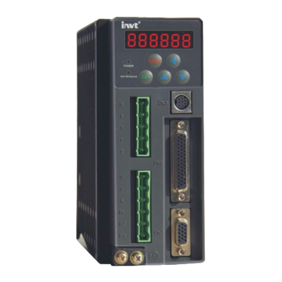
1.4 Illustrations of every parts of the servo drive .............................................8
1.5 External dimensions and installations sizes of the servo drive ..................9
2. INSPECTION........................................................................................................8
3. INSTALLATION ..................................................................................................9
3.1 Environmental Requirement .....................................................................10
3.2 Installation of the servo drive....................................................................11
4 Signal and wiring .................................................................................................14
4.1 System configuration.................................................................................15
4.2 Wiring of the main circuit (Connectors X1 and X2) ................................17
4.4 Connection with the PC or HOST (CN3 connector) ................................21
4.5 I/O signal wiring (CN1 connector) ...........................................................22
4.6 Wiring of the electromagnetic brake.........................................................39
5 Running and operation........................................................................................40
5.1 Running .....................................................................................................40
5.2 Display and operation................................................................................53
6 Detailed parameter description ..........................................................................60
6.1 Basic parameters (PA group parameters) ..................................................60
6.2 Gain and filter parameters (Pb group parameters)....................................71
6.3 Expansion parameters (Pc group parameters) ..........................................79
6.4 Status monitoring parameters (Pd group parameters)...............................94
7 Gain adjustment...................................................................................................99
7.1 General method for adjusting parameters .................................................99
7.2 Suppression of mechanical resonance.....................................................105
7.3 Gain switching function ..........................................................................106
8 Communication function...................................................................................108
8.1 General.....................................................................................................108
8.2 Topological structure ...............................................................................108
8.3 Communication protocol.........................................................................109
8.3.1 Protocol Content...................................................................................109
8.3.3 Communication Protocol Format.........................................................110
8.3.4 Command code and the communication data instructions ..................111
8.3.5 Error checkout of the communication frame means............................118
9 Fault processing..................................................................................................124
9.1 Meanings of the fault alarm codes and countermeasures .......................124
9.2 Meanings of the warning codes...............................................................126
.................................................................................................................................127
Contents
I
Contents
Advertisement
Table of Contents

Related Manuals for INVT CHS100


Summary of Contents for INVT CHS100
-
Page 1: Table Of Contents
Operation Manual of INVT CHS100 AC Servo Drive Contents Contents Contents ........................I Preface ........................1 Safety precautions .....................1 1 General ........................3 1.1 General technical specifications..............3 1.2 Nameplate of the servo drive ..............7 1.3 Power specification of every model............8 1.4 Illustrations of every parts of the servo drive ..........8 1.5 External dimensions and installations sizes of the servo drive ....9... -
Page 2: Contents
Operation Manual of INVT CHS100 AC Servo Drive Contents A.1 CN1 pin signal arrangement:..............127 A.2 CN2 pin signal arrangement:..............127 A.3 CN3 pin signal arrangement:..............128 Appendix B: List of function parameters............129 B.1 PA group parameters (Basic parameters) ..........129 B.2 Pb group parameters (Gain and filter parameters) .........130 B.3 Pc group parameters (Expansion parameters)........131... -
Page 3: Preface
Preface Thank you for using AC servo drive of the permanent magnet synchronous motor (hereinafter called “servo drive”) from Shenzhen INVT Electric Co., Ltd. Please carefully read and master the user’s manual before proper use. Improper use may cause abnormal running or shorten its service life or even directly damage the drive. -
Page 4: Safety Precautions
Safety Precautions Operation Manual of INVT CHS100 AC Servo Drive Safety precautions The precautions related to safe operation are classified into “Warnings” and “Notes”. Warning Points out potential danger which, if not avoided, may cause physical injury or death. Points out potential danger which, if not avoided, may result in mild or moderate physical injury and damage to the equipment. - Page 5 Safety Precautions Operation Manual of INVT CHS100 AC Servo Drive Wiring: Only qualified electricians are allowed to carry out the wiring. Otherwise there is danger of electrical shock or fire. The grounding terminals of the drive and motor must be grounded with proper techniques.
- Page 6 Safety Precautions Operation Manual of INVT CHS100 AC Servo Drive Do not touch the radiator or the external braking resistor during running. They may become very hot and burn your fingers. Maintenance and inspection: Before doing any inspection and maintenance, be sure to...
- Page 7 Operation Manual of INVT CHS100 AC Servo Drive 1 General 1 General 1.1 General technical specifications The standard specifications of the AC permanent magnet synchronous servo drive are listed in the table below: Table 1-1 Standard specifications of servo drive...
- Page 8 Operation Manual of INVT CHS100 AC Servo Drive 1 General Specifications Servo drive 100W~400W 0.75kW~1.5kW 2kW~5kW Input 13 ways of optical coupling isolation input Switch signal Output 7 ways of open-collector output Input 2 ways, range: DC -10V~+10V Analog Output...
-
Page 9: General
Operation Manual of INVT CHS100 AC Servo Drive 1 General Specifications Servo drive 100W~400W 0.75kW~1.5kW 2kW~5kW Frequency 500Hz response The max speed is 5000r/min, the min speed is Speed control 0.1r/min, and the speed regulation range is range 1:50000 Analog speed command DC 0~±10V/max rotation speed... - Page 10 Operation Manual of INVT CHS100 AC Servo Drive 1 General Specifications Servo drive 100W~400W 0.75kW~1.5kW 2kW~5kW Other Indoor (without direct sunshine), free from environmental corrosive, flammable gasses, oil mist, dust conditions Allowable Should be derated if the altitude is higher than...
-
Page 11: Nameplate Of The Servo Drive
Operation Manual of INVT CHS100 AC Servo Drive 1 General 1.2 Nameplate of the servo drive Fig. 1-1 Nameplate of the servo drive Fig. 1-2 Meanings of the model... -
Page 12: Power Specification Of Every Model
Operation Manual of INVT CHS100 AC Servo Drive 1 General 1.3 Power specification of every model he power of every model is listed in the table below: Table 1-2 Power specification of every model Inputs Outputs Models Capacity Power Rated current... -
Page 13: External Dimensions And Installations Sizes Of The Servo Drive
Operation Manual of INVT CHS100 AC Servo Drive 1 General 1.5 External dimensions and installations sizes of the servo drive Fig. 1-4 External dimensions of 100W~1.5kW servo drive Table 1-3 External dimensions and installations sizes External dimensions Installation sizes Installation... -
Page 14: Inspection
Operation Manual of INVT CHS100 AC Servo Drive 2 Inspection 2. INSPECTION CAUTION ● Don’t install or use any servo drive that is damaged or has fault parts, otherwise physical injury may occur. Check the following items after unpacking the servo drive and servo motor, 1.... -
Page 15: Installation
Operation Manual of INVT CHS100 AC Servo Drive 3 Installation 3. INSTALLATION WARNING ● Only qualified people are allowed to operate on the drive device/system. Ignoring the instructions in “warning” may cause serious physical injury or death or property loss. Only qualified electricians are permitted to design, install, commission and operate on the device/system. -
Page 16: Environmental Requirement
Operation Manual of INVT CHS100 AC Servo Drive 3 Installation 3.1 Environmental Requirement 3.1.1 Temperature Environment temperature range: -10°C ~ +45°C. 3.1.2 Relative humidity RH≤ 90%. No condensation is allowed. 3.1.3 Altitude The servo drive can run at the rated power if the installation site is less than 1000m(including 1000m) above the sea level. -
Page 17: Installation Of The Servo Drive
Operation Manual of INVT CHS100 AC Servo Drive 3 Installation 3.2 Installation of the servo drive 3.2.1 Installation The drive can be rack mounted. On the rear panel of the drive, there are two M5 mounting holes in the bottom left corner and top right corner to fix the drive tightly on a vertical plane. - Page 18 Operation Manual of INVT CHS100 AC Servo Drive 3 Installation The servo drive can be shelf mounted by mounting bracket. Mounting bracket Fig. 3-3 Schematic diagram of the shelf mounting form of the servo drive 3.2.2 Installation direction and spacing Please install the servo drive vertically and keep sufficient space around it for ventilation.
- Page 19 Operation Manual of INVT CHS100 AC Servo Drive 3 Installation 2) To install several sets: 100mm or more 40mm 40mm 20mm 20mm 20mm or more or more or more or more or more 100mm or more Fig. 3-4 Installation of several servo drives 3.2.3 Avoid intrusion of foreign objects...
-
Page 20: Signal And Wiring
Operation Manual of INVT CHS100 AC Servo Drive 4 Signal and wiring 4 Signal and wiring Only qualified electricians are allowed to operate on the drive for the insurance of a safe running of the servo drive. Never carry out any insulation or voltage withstand tests on the cables connecting with the servo drive. -
Page 21: System Configuration
Operation Manual of INVT CHS100 AC Servo Drive 4 Signal and wiring 4.1 System configuration 4.1.1 Connection diagram of the servo drive and external equipment Fig. 4-1 Connection diagram of the servo drive and external equipment The electromagnetic contactor is used to switch on/off the power supply of the main circuit of the servo drive. - Page 22 Operation Manual of INVT CHS100 AC Servo Drive 4 Signal and wiring 4.1.2 Cable diameter selection Table 4-1 Cable diameter selection Drives Cable diameter of the main circuit CHS100-0R1-2 0.75 to 2.0mm CHS100-0R2-2 AWG14 to AWG18 CHS100-0R4-2 CHS100-0R7-2 2.0mm CHS100-1R0-2...
-
Page 23: Wiring Of The Main Circuit (Connectors X1 And X2)
Operation Manual of INVT CHS100 AC Servo Drive 4 Signal and wiring 4.2 Wiring of the main circuit (Connectors X1 and X2) 4.2.1 Overview Check whether the phase number/voltage grade of the AC power supply are consistent with those identification on the nameplate of the drive. - Page 24 Operation Manual of INVT CHS100 AC Servo Drive 4 Signal and wiring 4.2.2 Wiring diagram of single phase 220V power input The user is required to make this emergency stop protection circuit. Fit surge absorbing devices on both ends of the electromagnetic contactor winding.
- Page 25 Operation Manual of INVT CHS100 AC Servo Drive 4 Signal and wiring 4.2.3 Wiring diagram of three-phase 220V power input The user is required to make this emergency stop protection circuit. Fit surge absorbing devices on both Breaker 3-phase AC reactor ends of the electromagnetic contactor winding.
- Page 26 Operation Manual of INVT CHS100 AC Servo Drive 4 Signal and wiring 4.3 Wiring of the encoder (connector CN2) 4.3.1 Overview The distance between the servo motor Power and the servo drive should not exceed supply 20m. Keep a distance of at least 30cm between the encoder wire, motor cable and power cable.
-
Page 27: Connection With The Pc Or Host (Cn3 Connector)
Operation Manual of INVT CHS100 AC Servo Drive 4 Signal and wiring Table 4-2 CN2 signal definition table CN2 pin 10 11 13 14 Definition V+ W+ A+ A- 5V U+ V- W- B- B+ U- Z- Z+ T_MT 4.4 Connection with the PC or HOST (CN3 connector) The servo drive provides two kinds of communication interface –... -
Page 28: I/O Signal Wiring (Cn1 Connector)
Operation Manual of INVT CHS100 AC Servo Drive 4 Signal and wiring 4.5 I/O signal wiring (CN1 connector) 4.5.1 Overview Within 3m The peripheral equipment such as the controller must be within 3m from the servo drive. The control cable must be kept at least... - Page 29 Operation Manual of INVT CHS100 AC Servo Drive 4 Signal and wiring 4.5.2 Wiring of the digital input circuit connection diagram when the power supply is self-provided by user: Digital input terminals such as SON, etc. Digital input terminals such as SON, etc.
- Page 30 Operation Manual of INVT CHS100 AC Servo Drive 4 Signal and wiring current) of the servo drive or 12V – 24V power supply provided by the user. 4.5.3 Wiring of the pulse input circuit Connection Twisted Shielded method 1 pair...
- Page 31 Operation Manual of INVT CHS100 AC Servo Drive 4 Signal and wiring Connection method 2, the maximum frequency of input pulse is 200kHz; please select the current-limiting resistance as listed in the table below: Parameters of the resistor − ≈...
- Page 32 Operation Manual of INVT CHS100 AC Servo Drive 4 Signal and wiring When an inductive load is connected, be sure to fit this freewheeling diode. Output The max. loading capacity of terminals each output terminal: 30V, 50mA such as ALM, etc.
- Page 33 Operation Manual of INVT CHS100 AC Servo Drive 4 Signal and wiring Terminal AM26LS32 or Twisted Servo drive resistor equivalent chip pair Please connect the shielded wire according to equipment requirements Shielded wire Fig. 4-14 Wiring diagram of the frequency division output circuit of the differential...
- Page 34 Operation Manual of INVT CHS100 AC Servo Drive 4 Signal and wiring Open-collector mode: Please use high speed optical coupler Max. 30V, 50mA. 30V,50mA. Twisted pair Fig. 4-15 Wiring diagram of the frequency division output circuit of the open-collector encoder feedback signal Phase A and B of the encoder only provides differential output signal, phase Z provides differential output and open-collector output signals.
- Page 35 Operation Manual of INVT CHS100 AC Servo Drive 4 Signal and wiring 10V. The max output current is 3mA.
- Page 36 Operation Manual of INVT CHS100 AC Servo Drive 4 Signal and wiring 4.5.8 CN1 pin arrangement and signal explanation: 4.5.8.1 See the figure below for CN1 pin signals: Pin arrangement of connector CN1 Signal arrangement of connector CN1 Fig. 4-17 CN1 pin signal diagram 4.5.8.2 Power signal...
- Page 37 Operation Manual of INVT CHS100 AC Servo Drive 4 Signal and wiring 4.5.8.3 Digital input signals and their functions Table 4-5 Function table of digital input signals Symbol Pin No. Name Function Mode When a fault alarm occurs, you can short connect this terminal with COM-.
- Page 38 Operation Manual of INVT CHS100 AC Servo Drive 4 Signal and wiring Symbol Pin No. Name Function Mode When parameter PA.01 (control mode selection) is set as 3 – 5, this terminal can be used to switch between different control modes. The corresponding relationships of this terminal’s state and the control...
- Page 39 Operation Manual of INVT CHS100 AC Servo Drive 4 Signal and wiring Symbol Pin No. Name Function Mode short-circuit with COM-. In the positive travel limitation, the drive can automatically respond to the reverse speed command. This terminal signal takes effect when receiving a pulse.
- Page 40 Operation Manual of INVT CHS100 AC Servo Drive 4 Signal and wiring Symbol Pin No. Name Function Mode When parameter PA.16 is set as 0, this travel limit terminal signal is invalid. Internal speed command (speed mode)/speed limit Speed option...
- Page 41 Operation Manual of INVT CHS100 AC Servo Drive 4 Signal and wiring Symbol Pin No. Name Function Mode the output and the motor will stop. This terminal signal takes effect when receiving a pulse. When this terminal is disconnected with COM-, internal servo enabling can be conducted through parameter PA.03.
- Page 42 Operation Manual of INVT CHS100 AC Servo Drive 4 Signal and wiring Symbol Pin No. Name Function Mode short-circuiting this terminal with COM-, the servo motor will stop instantly. In the table above: the polarity of terminals SON, ZRS, CLA, PLL, and RPC can be reversed by setting parameter PC.58.
- Page 43 Operation Manual of INVT CHS100 AC Servo Drive 4 Signal and wiring Symbol Pin No. Name Function When the servo drive is in normal state, this signal output transistor is breakover. When the power supply Servo alarm is disconnected or the servo drive is in alarm state, this signal output transistor switches off.
- Page 44 Operation Manual of INVT CHS100 AC Servo Drive 4 Signal and wiring Symbol Pin No. Name Function output reverse, phase A leads phase B by 90º. The frequency division coefficient of phase A and phase B can be set through parameter Pc.55 and Pc.56.
-
Page 45: Wiring Of The Electromagnetic Brake
Operation Manual of INVT CHS100 AC Servo Drive 4 Signal and wiring 4.6 Wiring of the electromagnetic brake In the case the servo motor is used in a vertical shaft, the electromagnetic brake can be used to prevent or keep the falling speed of heavy objects when the servo drive is powered off. -
Page 46: Running And Operation
Operation Manual of INVT CHS100 AC Servo Drive 5 Running and operation 5 Running and operation 5.1 Running 5.1.1 Example of standard wiring 5.1.1.1 Standard wiring diagram for the position mode Servo drive Note 3 Note 4 Emergency stop Servo enabling... - Page 47 Operation Manual of INVT CHS100 AC Servo Drive 5 Running and operation 5.1.1.2 Standard wiring diagram for the speed mode Servo drive Note 3 Note 4 Emergency stop Servo enabling Fault alarm (Note 5) Zero speed clamp Servo ready Speed selection 1...
- Page 48 Operation Manual of INVT CHS100 AC Servo Drive 5 Running and operation detailed wiring instruction, please refer to chapter 4.5.5.; Fault alarm terminal (ALM) transistor is ON in normal (no fault) cases. 5.1.1.3 Standard wiring diagram for the torque mode...
- Page 49 Operation Manual of INVT CHS100 AC Servo Drive 5 Running and operation wiring instruction, please refer to chapter 4.5.2; Be sure to connect the diode with correct polarity. Otherwise the protection circuit may not be work normally. If the internal 24V power supply is used, the sum of the external relays current the should be less than 100mA.
- Page 50 Operation Manual of INVT CHS100 AC Servo Drive 5 Running and operation After all the above items are checked OK, switch on the power supply: 1) Sequence of powering ON/OFF The control circuit and the main circuit of the drive are supplied separately. In principle, when powering on, switch on the power supply of the control circuit (terminals r, t) first and then switch on the power supply of the main circuit (terminals R, S, T).
- Page 51 Operation Manual of INVT CHS100 AC Servo Drive 5 Running and operation After switching on the power supply of the main circuit, do Warning not touch the motor line terminals even if the servo is not started as this may cause electrical shock.
- Page 52 Operation Manual of INVT CHS100 AC Servo Drive 5 Running and operation example, the parameters of the regulator loop which affect the system performance and other similar parameters. For most parameters the factory default values are appropriate. Hereunder only some necessary parameters are listed:...
- Page 53 Operation Manual of INVT CHS100 AC Servo Drive 5 Running and operation 5.1.6 Servo enabling Do not operate the switches with wet hand as this may Warning cause electric shock. Please confirm the parameter setting before running. NOTE Otherwise unexpected running state of the machinery may occur;...
- Page 54 Operation Manual of INVT CHS100 AC Servo Drive 5 Running and operation zero speed and, after that, the motor is in a locked state. When the servo enabling terminal (SON) signal is set to OFF, the servo motor will stop. You can select the stopping method through setting parameter Pc.52.
- Page 55 Operation Manual of INVT CHS100 AC Servo Drive 5 Running and operation 5.1.8 Sequence diagram 5.1.8.1 Sequence diagram of power-on and servo ON Power-on process Servo on process Main power supply Main circuit powered on Control circuit Control power supply...
- Page 56 Operation Manual of INVT CHS100 AC Servo Drive 5 Running and operation 5.1.8.2 Sequence diagram of power loss during running Main power supply Main circuit power loss Note 1 Control power supply Control circuit power fail Servo fault (ALM) Fault alarm...
- Page 57 Operation Manual of INVT CHS100 AC Servo Drive 5 Running and operation 5.1.8.3 Servo OFF sequence in a locked state Servo enabling (SON) No fault alarm Servo fault (ALM) output Servo ready (RDY) output Dynamic brake signal Dynamic braking relay disconnected (note 2)
- Page 58 Operation Manual of INVT CHS100 AC Servo Drive 5 Running and operation 5.1.8.4 Servo OFF sequence in running state Servo enabling (SON) Servo fault (ALM) No fault alarm output Servo ready (RDY) output Dynamic braking relay disconnected (note 2) Dynamic brake signal...
-
Page 59: Display And Operation
Operation Manual of INVT CHS100 AC Servo Drive 5 Running and operation 5.1.8.5 Sequence of fault alarm Servo fault (ALM) No fault alarm output Servo ready (RDY) output PWM output Servo has output Servo has no output Dynamic brake signal... - Page 60 Operation Manual of INVT CHS100 AC Servo Drive 5 Running and operation Manufacturer’s LOGO Six 8-bit Nixie tubes POWER indicator of the main circuit 5 operate keys 3-color indicator Fig 5-8 Schematic diagram of the keypad Table 5-1 State of the 3-color indicator...
- Page 61 Operation Manual of INVT CHS100 AC Servo Drive 5 Running and operation b) Basic parameter setting mode: used to set the basic parameters; c) Gain and filtering parameter setting mode: used to set gain or filtering parameters; d) Expansion parameter setting mode: used to set the expansion parameters;...
- Page 62 Operation Manual of INVT CHS100 AC Servo Drive 5 Running and operation selection, press , the panel will display the value of corresponding parameters. Press again to return. See chapter 5.2.1 for the setting flow chart. Identifier Name Unit Accuracy...
- Page 63 Operation Manual of INVT CHS100 AC Servo Drive 5 Running and operation Identifier Name Unit Accuracy Instantaneous value of U phase output current 0.01 when a fault occurs Instantaneous value of phase V output current 0.01 when a fault occurs Bus voltage when a fault occurs 5.2.3 Parameter setting...
- Page 64 Operation Manual of INVT CHS100 AC Servo Drive 5 Running and operation a) JOG function: identifier is PE-dAF b) Restore default parameter function: identifier is When is selected, press , the system will switch into JOG mode automatically, the 3-color indicator will become green, and the panel will display the value of jog speed.
- Page 65 Operation Manual of INVT CHS100 AC Servo Drive 5 Running and operation Identifier Name Drive overtemperature fault Software overcurrent fault Over-pulse fault Communication fault Write/read overtime fault Forward travel limit warning Reverse travel limit warning Emergency stop warning Main circuit power-down warning Communication abnormality warning 5.2.6 Alarm clear...
-
Page 66: Detailed Parameter Description
Operation Manual of INVT CHS100 AC Servo Drive 6 Detailed parameter description 6 Detailed parameter description Sign description: P – position mode; S – speed mode; T – torque mode. The setting of the parameters marked with * can only take effect when the control circuit is powered-off and re-on. - Page 67 Operation Manual of INVT CHS100 AC Servo Drive 6 Detailed parameter description position mode, it can control the angular displacement of the servo motor with the pulse command and thus achieve the goal to control the displacement of the mechanical movement.
- Page 68 Operation Manual of INVT CHS100 AC Servo Drive 6 Detailed parameter description In this mode, it can switch between the speed mode and torque mode with the control mode switching terminal (MCH). The corresponding relationships of the terminal status and modes are:...
- Page 69 Operation Manual of INVT CHS100 AC Servo Drive 6 Detailed parameter description Position mode Torque mode Position mode Zero speed threshold (set with PC.05) Motor speed Mode switching signal (MCH) Fig. 6-3 Schematic diagram of position/torque mode switching 6: Factory reserved mode. Setting by the user is prohibited.
- Page 70 Operation Manual of INVT CHS100 AC Servo Drive 6 Detailed parameter description 18: Latest fault alarm code 19: Digital input state; 20: Digital output state; 21: Motor temperature; 22: DSP software version; 23: FPGA software version; 24: Encoder UVW feedback value;...
- Page 71 Operation Manual of INVT CHS100 AC Servo Drive 6 Detailed parameter description Electronic gear = ; In the formula, : The numerator of the electronic gear; : The denominator of the electronic gear; Below is the schematic diagram of the electronic gear in the system:...
- Page 72 Operation Manual of INVT CHS100 AC Servo Drive 6 Detailed parameter description (SC1, SC2) we can select which group of parameters is used to give out the electronic gear. The corresponding relationships are listed in the table below: Position mode...
- Page 73 Operation Manual of INVT CHS100 AC Servo Drive 6 Detailed parameter description SC2). See chapter 4.5.8.3 for details. 1: External analog speed command. At this time we can control the speed of the servo motor by applying a voltage between -10V and 10V on the analog speed input terminals (VA).
- Page 74 Operation Manual of INVT CHS100 AC Servo Drive 6 Detailed parameter description It is used to select the input manner of the torque command in the torque mode: 0: Internal torque command. At this time we can set the desired torque by setting the internal torque command parameter (PA.11).
- Page 75 Operation Manual of INVT CHS100 AC Servo Drive 6 Detailed parameter description Speed/torque mode Internal speed/speed limit 3 Internal speed/speed limit 4 0: OFF (the terminal is disconnected with COM-); 1: ON (the terminal is connected with COM-). In the torque mode, this group of parameters is used to set the value of the internal speed limit.
- Page 76 Operation Manual of INVT CHS100 AC Servo Drive 6 Detailed parameter description absolute value of the speed command is larger than the value of this parameter, the magnitude of the actual speed setting will be limited by this parameter, the direction is the same as that of the original speed command.
-
Page 77: Gain And Filter Parameters (Pb Group Parameters)
Operation Manual of INVT CHS100 AC Servo Drive 6 Detailed parameter description Function Name Unit Range Default Mode code PA.17 E-stop shield P.S.T This parameter is used to set the input signal of the emergency stop terminal (EMG) is active or inactive. If you want to shield the function of the E-stop, you can set this parameter. - Page 78 Operation Manual of INVT CHS100 AC Servo Drive 6 Detailed parameter description Function Name Unit Range Default Mode code Pb.02 Position feed-forward gain 0~100.0 This parameter is used to set the position feed-forward gain. When it is set as 100%, the retention pulse at a certain speed is almost zero.
- Page 79 Operation Manual of INVT CHS100 AC Servo Drive 6 Detailed parameter description chapter 7 for the debugging method of this group of parameters. Function Name Unit Range Default Mode code Pb.06 2nd position gain 1~30000 1000 This parameter is used to set the gain of the position loop. When the setting is increased, the position response will be improved, but this parameter may easily cause vibration and noise.
- Page 80 Operation Manual of INVT CHS100 AC Servo Drive 6 Detailed parameter description speed loop. See description of parameters Pb.17 and Pb.16 for details. Refer to chapter 7 for the debugging method of this group of parameters. Function Name Unit Range...
- Page 81 Operation Manual of INVT CHS100 AC Servo Drive 6 Detailed parameter description the speed change more gently in the case the speed analog input changes largely. See the figure below: Analog speed command Speed After filtering After filtering Time t Fig.
- Page 82 Operation Manual of INVT CHS100 AC Servo Drive 6 Detailed parameter description Function Name Unit Range Default Mode code Pb.15 Speed detect filter time 256μs 0~6000 This parameter is used to set the time constant of the speed detect filter.
- Page 83 Operation Manual of INVT CHS100 AC Servo Drive 6 Detailed parameter description 1st gain 2nd gain 1st speed integration time 2nd speed integration constant (Pb.05) time constant (Pb.08) Function Name Unit Range Default Mode code Gain switching Pb.17 condition This parameter is used to select how to switch the gain under a special condition. The switching modes are: 0: Manual gain switching;...
- Page 84 Operation Manual of INVT CHS100 AC Servo Drive 6 Detailed parameter description When parameter Pb.17 is set as 2, it is used to set the retention pulse threshold for gain switching. When parameter Pb.17 is set as 3, it is used to set the speed threshold for gain switching.
-
Page 85: Expansion Parameters (Pc Group Parameters)
Operation Manual of INVT CHS100 AC Servo Drive 6 Detailed parameter description Function Name Unit Range Default Mode code 2nd trap wave Pb.22 50~2000 2000 P.S.T frequency This parameter is used to set the frequency of the 2nd trap wave filter for suppressing resonance. - Page 86 Operation Manual of INVT CHS100 AC Servo Drive 6 Detailed parameter description Speed Max. speed Set speed Time t Fig 6-10 Schematic diagram of ACC/DEC time Function Name Unit Range Default Mode code Pc.01 DEC time 0~20000 DEC time means that in the case of internal reference speed command, the required time for the setting speed decrease from 3000r/min to 0r/min.
- Page 87 Operation Manual of INVT CHS100 AC Servo Drive 6 Detailed parameter description Speed Time t Fig 6-11 Schematic diagram of S curve ACC/DEC time Function Name Unit Range Default Mode code Pc.03 S curve DEC time 0~1000 In a case of internal reference speed command, this parameter is used to set the duration of the circular arc segment during S curve decelerating and thus to achieve the goal of smoothly stopping.
- Page 88 Operation Manual of INVT CHS100 AC Servo Drive 6 Detailed parameter description Function Name Unit Range Default Mode code Range of position Pc.06 pulse 0~10 reaching This parameter is used to set the range of position reaching. When the deviation...
- Page 89 Operation Manual of INVT CHS100 AC Servo Drive 6 Detailed parameter description Function Name Unit Range Default Mode code Internal speed/speed Pc.10 r/min -5000.0~5000.0 500.0 limit 3 Internal speed/speed Pc.11 r/min -5000.0~5000.0 1000.0 limit 4 The functions of this group of parameter are the same as parameter PA.09, PA.10.
- Page 90 Operation Manual of INVT CHS100 AC Servo Drive 6 Detailed parameter description Function Name Unit Range Default Mode code Pc.18 Factory reserved Matching resistor Pc.19 P.S.T selection When adopt 485 communication, the matching resistors of equal resistance should be fitted at the starting end and finishing end of the network.
- Page 91 Operation Manual of INVT CHS100 AC Servo Drive 6 Detailed parameter description 3:57600bps; 4:115200bps. Function Name Unit Range Default Mode code Communication parity Pc.23 0~17 P.S.T mode 0: None (8, N, 1) for RTU; 1: Even (E, 8, 1) for RTU;...
- Page 92 Operation Manual of INVT CHS100 AC Servo Drive 6 Detailed parameter description system, after completion of data processing, the system will wait until the response delay time is over before transmitting data to the upper PC. Function Name Unit Range...
- Page 93 Operation Manual of INVT CHS100 AC Servo Drive 6 Detailed parameter description Function Name Unit Range Default Mode code Voltage lower limit of AI Pc.28 -10.00~10.00 -10.00 Corresponding setting Pc.29 r/min -5000~5000 of lower limit of AI 1 Voltage upper limit of AI Pc.30...
- Page 94 Operation Manual of INVT CHS100 AC Servo Drive 6 Detailed parameter description torque command signal. Its input has directionality. We can adjust the corresponding relationship between the AI voltage and torque command by setting this group of parameters to meet the requirements of different applications. In the speed mode, it is used as torque limit signal.
- Page 95 Operation Manual of INVT CHS100 AC Servo Drive 6 Detailed parameter description Function Name Unit Range Default Mode code Pc.42 Voltage upper limit of AO 2 0.00~10.00 10.00 P.S.T Corresponding of upper Pc.43 0.0~100.0 100.0 P.S.T limit of AO 2 This group of parameters defines the relationships between the analog output voltage and its corresponding setting.
- Page 96 Operation Manual of INVT CHS100 AC Servo Drive 6 Detailed parameter description Speed Voltage Fig. 6-13 Schematic diagram of AO setting Function Name Unit Range Default Mode code Pc.44 Offset voltage of AI1 -2.00~2.00 0.00 Pc.45 Offset voltage of AI2 -2.00~2.00...
- Page 97 Operation Manual of INVT CHS100 AC Servo Drive 6 Detailed parameter description Sampled voltage value Before setting After setting Actual voltage value Fig. 6-14 Schematic diagram of analog offset voltage Function Name Unit Range Default Mode code Pc.48 AO 1 selection P.S.T...
- Page 98 Operation Manual of INVT CHS100 AC Servo Drive 6 Detailed parameter description electromagnetic brake This parameter is used to set the braking delay time of the electromagnetic brake. The servo is OFF or an alarm occurs in the running state, in this condition, the speed may be relatively high, so the output transistor of the brake releasing terminal (BRK) signal can be turned off after a delay time.
- Page 99 Operation Manual of INVT CHS100 AC Servo Drive 6 Detailed parameter description report a braking overload fault (Er-bCE) by mistake or cause burnout of the braking resistor. The regenerative braking overload protection time is proportional to these two parameters. When Pc.54=0, the internal braking resistor is active.
-
Page 100: Status Monitoring Parameters (Pd Group Parameters)
Operation Manual of INVT CHS100 AC Servo Drive 6 Detailed parameter description number. Each bit corresponds to a digital input. 0 indicates that the polarity does not change. 1 indicates to reverse the polarity of the digital quantity corresponding to this bit. - Page 101 Operation Manual of INVT CHS100 AC Servo Drive 6 Detailed parameter description Function code Symbol Name Unit Accuracy Higher 5 bits of command Pd.04 dP-rPH pulse pulse accumulation Count and display the higher 5 bits of the number of the accumulated input pulses. The displayed number is the pulse number before being amplified by the electronic gear.
- Page 102 Operation Manual of INVT CHS100 AC Servo Drive 6 Detailed parameter description Function code Symbol Name Unit Accuracy RMS value of current Pd.10 dP-cur 0.01 output current Display the RMS value of motor. Function code Symbol Name Unit Accuracy Pd.11...
- Page 103 Operation Manual of INVT CHS100 AC Servo Drive 6 Detailed parameter description Function code Symbol Name Unit Accuracy Pd.19 dP-in Digital input state Pd.20 dP-ou Digital output state This value is a hexadecimal number arranged in the sequence of the digital quantities to indicate the state of all digital quantities.
- Page 104 Operation Manual of INVT CHS100 AC Servo Drive 6 Detailed parameter description Function code Symbol Name Unit Accuracy Instantaneous value of Pd.25 dP-ia 0.01 phase U output current Display the instantaneous value of current phase U output current. Function code...
-
Page 105: Gain Adjustment
Operation Manual of INVT CHS100 AC Servo Drive 7 Gain adjustment 7 Gain adjustment 7.1 General method for adjusting parameters At present, the parameter adjustment of the servo drive of our company needs to be performed manually. When the servo system oscillates or the control performance becomes not sound, you can improve the system performance or eliminate the oscillation by adjusting the parameters of the speed loop and position loop. - Page 106 Operation Manual of INVT CHS100 AC Servo Drive 7 Gain adjustment that abnormal sound and vibration are not generated, gradually increase the gain of the speed loop to the maximum. 2) Gradually decrease the gain of the speed loop while increasing the gain of the position loop.
- Page 107 7.1.1 Adjustment of the gain of the position loop The position control block diagram of the CHS100 series servo drive is shown in the figure below. The gain parameters that can be adjusted in the position mode are...
- Page 108 Operation Manual of INVT CHS100 AC Servo Drive 7 Gain adjustment Position Position Command Position smoothing feed-forward filter Speed Electroni Low-pass Position Trap filter c gear controller filter controller Speed test filter Torque controller Encoder Motor Encoder frequency division Fig. 7-1 Block diagram of position control...
- Page 109 (Pc.55, Pc.56) can be used to change the frequency of the output pulse. 7.1.2 Adjustment of the gain of the speed loop The speed control block diagram of the CHS100 series servo drive is shown in the figure below. The gain parameters that can be adjusted in the speed mode are marked on the block diagram.
- Page 110 7.1.3 Adjustment of the gain of the torque loop The torque control block diagram of the CHS100 series servo drive is shown in the figure below. The gain parameters that can be adjusted in the torque mode are marked...
-
Page 111: Suppression Of Mechanical Resonance
Operation Manual of INVT CHS100 AC Servo Drive 7 Gain adjustment Torque command Torque command processing Speed limit command Speed Low-pass Trap filter Torque limit controller filter Speed test filter Torque controller Encoder frequency Encoder Motor division Fig. 7-3 Block diagram of torque control... -
Page 112: Gain Switching Function
Operation Manual of INVT CHS100 AC Servo Drive 7 Gain adjustment Pb.22, Pb.23 respectively. The position of the trap wave filters in the speed loop is as shown in Fig. 7-2. Note: for the servo system, the trap wave filter is a kind of lagging factor. Therefore, incorrect setting of the trap wave filters or too large suppression extent may strengthen vibration sometimes. - Page 113 Operation Manual of INVT CHS100 AC Servo Drive 7 Gain adjustment time, when no pulse is inputted, the system uses the 1st gain for adjustment. After the pulse command is inputted, it smoothly switches to the 2nd gain. After the command input stops, in 2ms, if the speed falls below the setting of Pb.18, it will switch to the 1st...
-
Page 114: Communication Function
Read/write the function parameters of the servo drives Monitor the operating state of the servo drives Form a multi-axis control system 8.2 Topological structure CHS100 series servo drive is connected in the “Single Master Multi-slave” control network with RS232/RS485 bus. 8.2.1 Communication with single set Servo drive... -
Page 115: Communication Protocol
RS485 / RS232 converter connector 8.3 Communication protocol The CHS100 series servo drive are provided with two types of communication interfaces: RS485 and RS232. It adopts international standard ModBus communication protocol to perform master-slave communication. The user can realize centralized control through PC/PLC, upper control PC, etc. -
Page 116: Communication Protocol Format
Operation Manual of INVT CHS100 AC Servo Drive 8 Communication Function same communication protocol. The master can communicate with a certain salve, as well as, send broadcast message to all slaves. For the separately-visiting inquiry/command of the master, the slave should return a message as the response. -
Page 117: Command Code And The Communication Data Instructions
Operation Manual of INVT CHS100 AC Servo Drive 8 Communication Function Table 8-2: The message frame in RTU mode The start bit Data The tailed device command checkout address code T1-T2-T3-T4 8Bit 8Bit N 8Bits 16Bit T1-T2-T3-T4 The Modbus minimum idle time between frames should be no less than 3.5 bytes. The network device is detecting, even during the interval time, the network bus. - Page 118 Operation Manual of INVT CHS100 AC Servo Drive 8 Communication Function High byte of data number Low byte of data number Low byte of CRC CHK High byte of CRC CHK T1-T2-T3-T4 (transmission time of 3.5 bytes) Table 8-4 The RTU slave device reply is : START T1-T2-T3-T4 (transmission time of 3.5 bytes)
- Page 119 Operation Manual of INVT CHS100 AC Servo Drive 8 Communication Function ‘0’ Low byte of data number ‘2’ LRC CHK Hi ‘F’ LRC CHK Lo ‘5’ END Lo END Hi Table 8-6 The ASCII slave master device reply is START ‘:’...
- Page 120 Operation Manual of INVT CHS100 AC Servo Drive 8 Communication Function Table 8-7 The RTU master device request command is: START T1-T2-T3-T4 (transmission time of 3.5 bytes) ADDR High byte of data address Low byte of data address High byte of write content...
- Page 121 Operation Manual of INVT CHS100 AC Servo Drive 8 Communication Function ‘6’ ‘0’ High byte of data address ‘1’ ‘0’ Low byte of data address ‘9’ ‘1’ High byte of write content ‘3’ ‘8’ Low byte of write content ‘8’...
- Page 122 Operation Manual of INVT CHS100 AC Servo Drive 8 Communication Function 8.3.4.3 Command code 08Hfor diagnosis Table 8-11 meaning of sub-function codes Sub-function Code Description 0000 Return to inquire information data For example: The inquiry information string is same as the response information string when the loop detection to address 01H of driver is carried out.
- Page 123 Operation Manual of INVT CHS100 AC Servo Drive 8 Communication Function START ‘:’ ‘0’ ADDR ‘1’ ‘0’ ‘8’ ‘0’ High byte of sub-function code ‘0’ ‘0’ Low byte of sub-function code ‘0’ ‘1’ High byte of data content ‘2’ ‘A’...
-
Page 124: Error Checkout Of The Communication Frame Means
Operation Manual of INVT CHS100 AC Servo Drive 8 Communication Function LRC CHK Lo ‘A’ END Hi END Lo 8.3.5 Error checkout of the communication frame means The error checkout of the frame can be divided into two parts: the bit checkout of the byte and the whole data checkout of the frame (CRC check or LRC check). - Page 125 Operation Manual of INVT CHS100 AC Servo Drive 8 Communication Function different, there is an error in the communication. During CRC, 0*FFFF will be stored. And then, deal with the continuous 6-above bytes in the frame and the value in the register. Only the 8Bit data in every character is effective to CRC, while the start bit, the tailed and the odd and even check bit is ineffective.
- Page 126 Operation Manual of INVT CHS100 AC Servo Drive 8 Communication Function 8.3.6 Address definition of communication data This chapter is the address definition of communication data used to control the running of the servo drives, acquire the state information of the servo drives and set relevant function parameters of the servo drives and so on.
- Page 127 Operation Manual of INVT CHS100 AC Servo Drive 8 Communication Function Table 8-6 Special function codes Function Address Explanation of data meaning description definition characteristics 0000H: Jog end 0001H: Jog start Communication 0002H: FWD jog start control 1000H 0003H: REV jog start...
- Page 128 Operation Manual of INVT CHS100 AC Servo Drive 8 Communication Function Function Address Explanation of data meaning description definition characteristics 2000H Channel 1 data starting address 3000H Channel 2 data starting address Internal speed/speed limit 1 0500H (PA.09) higher 16 bits...
- Page 129 Operation Manual of INVT CHS100 AC Servo Drive 8 Communication Function Modbus abnormal code Code Name Meaning Receiving function codes from the upper devices is not Illegal allowable. This may because these function codes can only function be applied to new devices or the slave device is dealing with this requirement in a wrong situation.
-
Page 130: Fault Processing
Operation Manual of INVT CHS100 AC Servo Drive 9 Fault Processing 9 Fault processing 9.1 Meanings of the fault alarm codes and countermeasures Code Name Causes Countermeasures EEPROM Er-EEP 1. EEPROM is damaged 1. Replace the drive fault 1. The encoder is not connected 1. - Page 131 Operation Manual of INVT CHS100 AC Servo Drive 9 Fault Processing Code Name Causes Countermeasures fault powering-up of the grid snubber relay 2. Replace the drive picked up 1. Replace with the drive 1. Run overload for a long and motor of higher...
-
Page 132: Meanings Of The Warning Codes
Operation Manual of INVT CHS100 AC Servo Drive 9 Fault Processing Code Name Causes Countermeasures power Replace with external braking resistor is braking resistor of higher relatively low power 1. Adjust PA.12 smaller 1. IPM module detects out decrease IPM module... -
Page 133: Appendix A Signal Arrangement Diagram Of Each Connector Of The Servo Drive
Operation Manual of INVT CHS100 AC Servo Drive Appendix A Appendix A Signal arrangement diagram of each connector of the servo drive A.1 CN1 pin signal arrangement: Pin arrangement of connector CN1 Signal arrangement of connector CN1 A.2 CN2 pin signal arrangement:... -
Page 134: Cn3 Pin Signal Arrangement
Operation Manual of INVT CHS100 AC Servo Drive Appendix A A.3 CN3 pin signal arrangement: CN3 pin No Definition CANL CANH RS485- RS485+... -
Page 135: Appendix B: List Of Function Parameters
Operation Manual of INVT CHS100 AC Servo Drive Appendix B Appendix B: List of function parameters P – position mode; S – speed mode; T – torque mode. The function codes prefixed with sign “*” indicate the setting of these parameters can only take effect after the system resets, restarts, or control circuit is powered off and repowered. -
Page 136: Pb Group Parameters (Gain And Filter Parameters)
Operation Manual of INVT CHS100 AC Servo Drive Appendix B B.2 Pb group parameters (Gain and filter parameters) Function Name Unit Range Default Mode code Pb.00 Rotational inertia ratio Time 0~30 P.S.T Pb.01 1st position gain 1~30000 Pb.02 Position feed-forward gain 0~100.0... -
Page 137: Pc Group Parameters (Expansion Parameters)
Operation Manual of INVT CHS100 AC Servo Drive Appendix B B.3 Pc group parameters (Expansion parameters) Function Name Unit Range Default Mode code Pc.00 ACC time 0~20000 Pc.01 DEC time 0~20000 Pc.02 S curve ACC time 0~1000 Pc.03 S curve DEC time... - Page 138 Operation Manual of INVT CHS100 AC Servo Drive Appendix B Function Name Unit Range Default Mode code Pc.30 Upper voltage limit of AI 1 -10.00~10.00 10.00 Corresponding setting of Pc.31 r/min -5000~5000 100.0 upper limit of AI 1 Pc.32 Lower voltage limit of AI 2 -10.00~10.00...
- Page 139 Operation Manual of INVT CHS100 AC Servo Drive Appendix B Function Name Unit Range Default Mode code Pulse range for over Pc.57 pulse 0~50000 20000 position Polarity reversing of digital Pc.58 0~11111 00000 P.S.T input...
-
Page 140: Pd Group Parameters (Monitoring Parameters)
Operation Manual of INVT CHS100 AC Servo Drive Appendix B B.4 Pd group parameters (monitoring parameters) Function Name Unit Range Default code Pd.00 dP-SPd Motor rotation speed r/min Lower 5 bits of feedback pulse Pd.01 dP-FPL pulse accumulation Higher 5 bits of feedback pulse Pd.02...
Need help?
Do you have a question about the CHS100 and is the answer not in the manual?
Questions and answers