Table of Contents

Related Manuals for ATS Pyro-Clean


Summary of Contents for ATS Pyro-Clean
- Page 1 INSTRUCTION MANUAL Pyrolytic Oven This manual contains important operating and safety information. Carefully read and understand the contents of this manual prior to the operation of this equipment. www.atspa.com MAN - Pyrolytic Oven - REV: Original...
- Page 2 Information in this document is subject to change without notice and does not represent a commitment on the part of Applied Test Systems (ATS). © Copyright Applied Test Systems 2018 For assistance with set-up or operation, contact the ATS service department. Please have this manual and product serial number available when you call. Telephone: +1-724-283-1212.
-
Page 3: Table Of Contents
Manual Contents A. Introduction ..........................1 A.1 Unpacking ................................1 A.2 Warranty Information ............................1 A.3 After Sale Support .............................. 1 A.4 Declaration of Conformity ........................... 2 B. Safety ............................3 B.1 For Owners, Operators, and Maintenance ......................3 B.2 Safety Instructions .............................. 3 B.3 Warnings ................................ - Page 4 D.6 How to Measure Oven Negative Pressure (Draft) .................... 15 D.7 How to Adjust to Oven Draft ..........................15 D.8 Pressure Switch for Draft Inducer Blower Motor ....................16 E. Software Overivew ........................17 E.1 Software Screen Map ............................17 E.2 Main Screen ..............................
- Page 5 Done Button ............................... 25 F. Operation ........................... 26 F.1 Important Operation Notifications ........................26 Warnings (Yellow) ............................26 Alarms (Orange) ............................26 Faults (Red) ............................... 26 F.2 Initial Start-Up: Empty Load ..........................26 F.3 Starting a Normal Load of Dirty Glasswear or Metal Parts ................27 Tips on Loading ............................
-
Page 6: Introduction
Retain all cartons and packing materials until the unit is operated and found to be in good condition. If damage has occurred during shipping, notify Applied Test Systems (ATS) and the carrier immediately. If it is necessary to file a damage claim, retain the packing materials for inspection by the carrier. -
Page 7: Declaration Of Conformity
A.4 Declaration of Conformity We hereby declare under our sole responsibility that this product conforms to the technical requirements of the following standards: EMC: EN 61000-3-2, EN 61000-3-3, EN 61326-1 Limits for harmonic current emissions (OV134510-33 only) Limits for voltage fluctuations and flicker (OV134510-33 only) Electrical equipment for measurement, control, and laboratory use;... -
Page 8: Safety
B. Safety B.1 For Owners, Operators, and Maintenance All ATS equipment is designed to be operated with the highest level of safety. This manual uses note, caution, and warning symbols throughout to draw your attention to important operational and safety information. - Page 9 For additional MSDS’s, or additional information concerning the handling of refractory ceramic products, please contact the ATS Service Department at +1-724-283-1212. WARNING: This warning is presented for compliance with California Proposition 65 and other regulatory agencies and only applies to the insulation in this product.
- Page 10 Data Sheets (MSDS) for information regarding proper handling and recommended protective equipment. For additional MSDS copies, or additional information concerning the handling of refractory ceramic products, please contact ATS Service Department at +1-724-283-1212. MAN - Pyrolytic Oven - REV: Original | B. Safety...
-
Page 11: System Overview
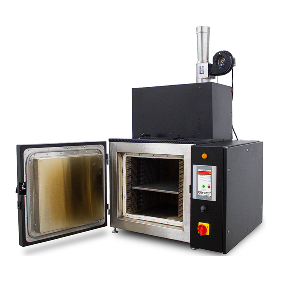
C. System Overview C.1 Equipment Parts Front of Unit Figure C.1: Pyrolytic Oven Front 1. Draft Inducer 6. Power Light 2. Oxidizer Chamber 7. HMI Touch Screen 3. Blow-Off Door 8. USB Port 4. Oven Chamber 9. Power Switch 5. Electrical Box MAN - Pyrolytic Oven - REV: Original | C. -
Page 12: Back Of Unit
Back of Unit Figure C.2: Pyrolytic Oven (Rear View) 1. Draft Inducer 5. Air Intake Filter 2. Oxidizer Chamber 6. Ethernet Port 3. Oven Chamber 7. Draft Inducer Power Outlet 4. Electrical Control Box 8. Power Cord MAN - Pyrolytic Oven - REV: Original | C. System Overview... -
Page 13: General Overview
C.2 General Overview The Pyrolytic Oven is designed to clean glass or metal parts contaminated with residues of various organic substances such as polymers, waxes, resins, asphalts, tars, or other similar contaminants. Cleaning is done entirely with heat, eliminating the use of solvent or chemical cleaning. Organic residues are thermally decomposed and vaporized from glass or metal parts at 900 degrees F. -
Page 14: Organic Residues That Can Be Cleaned
Organic Residues That Can Be Cleaned Virtually any contaminant which is organic in nature can be removed at the normal operating temperature of the cleaning oven, 950 degrees F. In recent years, new high temperature polymers have been developed which are very resistant to heat and are not easily removed thermally. -
Page 15: Limitations
For the oxidation stage, a cycle time is located on the settings screen, with an adjustable range of 1 to 1000 hours. The Factory setting of 2 hours is recommended for most applications. NOTE: For removing asphalts, a factory setting of 3 to 4 hours is recommended as asphalts are among the more difficult organics to remove. -
Page 16: Product Specifications
C.3 Product Specifications Environmental Operating: 17°C to 27°C; 20% to 80% relative humidity, non-condensing. Conditions Installation Category II (overvoltage) in accordance with IEC 664. Pollution Degree 2 in accordance with IEC 664. Altitude Limit 2,000 Meters Storage -25°C to 65°C; 10% to 85% relative humidity Cleaning Temperature 800 –... -
Page 17: Installation
NOTE: Allow at least 4 inches of space between the oven and any vertical surfaces. NOTE: Pyro-Clean ovens are supplied with a power cord but not a plug. The plug will need to handle 240Vac @ 30A. -
Page 18: Electrical Service
D.3 Electrical Service The oven has been completely tested and checked at ATS before shipment. A power cord 10 feet long is supplied with the oven. You will need to supply a plug and receptacle for 30 amp, 240 volt, single phase. The total power use of the Pyrolytic Oven unit is about 6600 watts. -
Page 19: Venting To The Outdoors Through Wall Or Roof
For convenience, the system will allow you to turn on the draft inducer and see the current draft. See the “Manual Screen” section of this manual, but please consult ATS if uncertain how to measure the small negative pressures required by Pyrolytic Ovens. -
Page 20: How To Measure Oven Negative Pressure (Draft)
CAUTION: IF THE OVEN IS EXHAUSTED INTO A POWERED VENT SYSTEM SUCH AS A LAB HOOD, THE HOOD EXHAUST SYSTEM SHOULD BE ON ALL THE TIME THAT THE OVEN IS ON. DO NOT LEAVE THE BUILDING AND SHUT OFF THE HOOD, THEREBY SHUTTING OFF THE EXHAUST SYSTEM FOR THE OVEN. -
Page 21: Pressure Switch For Draft Inducer Blower Motor
See Figure D.1 for pipe location. Figure D.1 - Oxidizer Pipe It is important to recognize that Pyrolytic Ovens manufactured by ATS are not ordinary ovens. Pyrolytic Oven systems are specialized, high-temperature systems specifically designed and built for thermal cleaning of valuable objects such as lab glass or metal parts. -
Page 22: Software Overivew
E. Software Overivew E.1 Software Screen Map Figure E.1 shows the Pyrolytic Oven’s software screens. Pyrolytic Oven Menu Flow Main Screen View Cycle Time VNC Password Language Settings IP Address Password Current Time Manual Password Delayed Cycle Start Password Passwords Reset Oven Clean Time Reset Catalyst... -
Page 23: Main Screen
E.2 Main Screen Figures E.2 shows the Main Screen that is shown when the Pyrolytic Oven is started. It allows you to setup and run oven cycles. Figure E.2 - Main Screen This screen will show values for Oxidizer chamber temperature and Oven temperature. It also has several controls to set-up and run the oven. -
Page 24: State Status Indicator Bar
Figure E.3 - Main Screen, Alarm State Figure E.4 - Main Screen, Delay Start State Figure E.4 illustrates what the Main Screen looks like when the system is in delay start state. Note the Remaining Time displayed. This will show up for the Preheat Delay, Oven Soak, and the Run Cycle states and will display the time remaining for this part of the cycle. -
Page 25: Oven Soak
Oven Soak Indicates the oxidizer chamber is stable at temperature, after which the oven starts to soak temperature. It is at this stage that “smoke” is generated to burn off in the oxidization chamber. The Oxidization chamber and the oven will interact so that the oxidization chamber is not overloaded. -
Page 26: View Screen
The screen will show the current version of the software in the PLC and HMI. This is very important information, and is most often ask for when calling into ATS service. A user ID should be set to the user access you wish to use. -
Page 27: Passwords Button
Passwords Button Will not be displayed until the correct ID and Password has been entered. Once it is displayed, pressing it will go to the password screen. (Default ID: 2, Password: 222222). Standardize Button Will not be displayed until the correct ID and Password has been entered. Once it is displayed, pressing it will go to the standardize screen. -
Page 28: Settings Screen
E.5 Settings Screen Figure E.14 shows the Settings Screen. It is shown when the Settings Button is pressed on the View Screen. It allows set up of the system. Figure E.14 - Settings Screen Cycle Time The amount of time the oven sits at cycle temperature before it shuts off and goes into cool down. IP Address Used to allow someone at a remote location to monitor the system using a VNC viewer program. -
Page 29: Done Button
Done Button Will return you to the View Screen. E.6 Manual Screen Figure E.15 is the Manual Screen. It is shown when the Manual Button is pressed on the View Screen. It allows trouble shooting of the system. Caution should be used as all system safety features are disabled during Manual operation. Figure E.15 - Manual Screen Six Buttons Across Top of Screen Allow you to turn individual sub-systems on and off to test them. -
Page 30: Current Draft
Current Draft Shown to help in the adjustment of the draft tube during ventilation set-up. Done Button Will return you to the View Screen. MAN - Pyrolytic Oven - REV: Original | E. Software Overview... -
Page 31: Operation
Warnings, alarms, and faults are color coded in yellow, orange, and red. Refer to the list below for descriptions of these common operation notifications. If additional assistance is required, contact the ATS Service Department at +1-724-283-1212. -
Page 32: Starting A Normal Load Of Dirty Glasswear Or Metal Parts
1. After the Pyro-Clean Oven has been installed and properly vented with the correct draft, it is ready to operate. However, it is best to run the oven through a short cleaning cycle with it empty to: a. Familiarize the operator with the normal operating sequence and location of the controls. -
Page 33: Cycle Times For Cleaning
back of the oven to prevent any organic material from dripping on the oven door gaskets. F.4 Cycle Times for Cleaning The Pyrolytic Oven is equipped with an Automatic Cycle Time Feature which adjusts itself to the load placed in the oven. -
Page 34: Additional Operation Precautions
WARNING: Do not overload the oven with metal parts containing heavy organic residues. The maximum load for the Pyro-Clean Oven is 1 to 2 pounds of polymer or plastic. Consult Applied Test Systems if heavier loads need to be cleaned. - Page 35 start to heat to 900°F. The status display will change to “Oven Soak”. 11. In the “Oven Soak” stage, the oven will heat up creating smoke that gets burnt off in the oxidizer chamber. If the oxidizer temperature goes over 1500°F it will shut off the oven heat until the temperature goes below 1350°F. It will then turn the oven back on.
-
Page 36: Troubleshooting
G. Troubleshooting G.1 Troubleshooting Electrical Problems A ladder wiring diagram for the Pyrolytic Oven is included in this manual, along with a drawing of the inside of the control box showing the lay-out of the parts and their identification. A qualified electrician should find this sufficient to locate any electrical problems with the unit. -
Page 37: Maintenance
H. Maintenance H.1 Door Seals and Gaskets The oven door has two gaskets. One is a high temperature gasket which serves both as a seal and a heat barrier to protect the silicone gasket. Periodic replacement of the high temperature gasket is considered necessary routine maintenance. -
Page 38: Replacement Of Parts
H.6 Replacement of Parts When electrical components must be replaced, refer to the Parts List included in this manual for the appropriate descriptions. Consult Factory for current prices. Electrical parts on the oven are warrantied for one year. Every Six Months 1. -
Page 39: Every Twelve Months
b. Empty the catch tray in the bottom of the oven (into floor sweeps). 6. Clean Electronics Cabinet a. Vacuum out any areas in the electronics cabinet that appear dirty. Every Twelve Months Perform the 6 month steps, plus: 1. Replace catalyst trays a. -
Page 40: New Hmi Software
Part No. Afterburner (Oxidizer) Parts XXXXXXX Thermocouple, K, 1/8” by 6” long, 36” leads XXXXXXX Air Pump, Oxidizer Part No. Oven Trays & Pans XXXXXXX Tray, S.S., Regular XXXXXXX Tray, S.S., Catalytic XXXXXXX Pan, Drain, S.S. H.8 New HMI Software From time to time a new software version may come out for the HMI. - Page 41 Figure H.2 - Second Pop-Up Window 5. Next will appear 2 subdirectories - pccard and usbdisk. Click usbdisk, select disk_a_1, and click OK. Figure H.3 - disk_a_1 6. The necessary files will now be downloaded. 7. When done, remove the flash drive and replace the USB port cap. MAN - Pyrolytic Oven - REV: Original | H.
-
Page 42: Appendix A: Warranty
Appendix A: Warranty Your Applied Test Systems product has been manufactured and inspected by experienced craftsmen. Applied Test Systems warrants, for the original purchaser, each product to be free from defects in material and workmanship for a period of thirteen (13) months from date of shipment or twelve (12) months from date of installation - whichever comes first. -
Page 43: Appendix B: Wiring Diagrams
Appendix B: Wiring Diagrams MAN - Pyrolytic Oven - REV: Original | Appendix B: Wiring Diagrams... - Page 44 MAN - Pyrolytic Oven - REV: Original | Appendix B: Wiring Diagrams...
- Page 45 MAN - Pyrolytic Oven - REV: Original | Appendix B: Wiring Diagrams...
- Page 46 MAN - Pyrolytic Oven - REV: Original | Appendix B: Wiring Diagrams...
- Page 47 MAN - Pyrolytic Oven - REV: Original | Appendix B: Wiring Diagrams...
- Page 48 MAN - Pyrolytic Oven - REV: Original | Appendix B: Wiring Diagrams...
-
Page 49: Appendix C: Image Glossary
Appendix C: Image Glossary Figure A.1 - ATS Sample Data Tag ...........................1 Figure C.1 - Pyrolytic Oven Front ..........................6 Figure C.2 - Pyrolytic Oven (Rear View) ........................7 Figure D.1 - Oxidizer Pipe ............................16 Figure E.1 - Pyrolytic Oven Software Screen Map ....................17 Figure E.2 - Main Screen............................18...
Need help?
Do you have a question about the Pyro-Clean and is the answer not in the manual?
Questions and answers