
Related Manuals for wtw AmmoLyt 700 IQ


Summary of Contents for wtw AmmoLyt 700 IQ
- Page 1 Operating manual ® AmmoLyt 700 IQ IQ S ammonium sensor ENSOR ba75353e05 03/2006...
- Page 2 The latest version of the present operating manual can be found on the Internet under www.WTW.com. © Copyright Weilheim 2006, WTW GmbH Reprinting - even as excerpts - is only allowed with the explicit written authorization of WTW GmbH, Weilheim. Printed in Germany. ba75353e05 03/2006...
-
Page 3: Table Of Contents
® AmmoLyt 700 IQ Contents Overview ........1-1 How to use this component operating manual . - Page 4 ® Contents AmmoLyt 700 IQ Technical data ....... 8-1 Measuring properties ......8-1 Operating characteristics .
-
Page 5: Overview
® AmmoLyt 700 IQ Overview How to use this component operating manual Structure of the operating IQ S ENSOR manual Fig. 1-1 Structure of the IQ S operating manual ENSOR operating manual has a modular structure like the IQ S ENSOR itself. -
Page 6: Structure Of The Ammolyt ® 700 Iq Ammonium Sensor
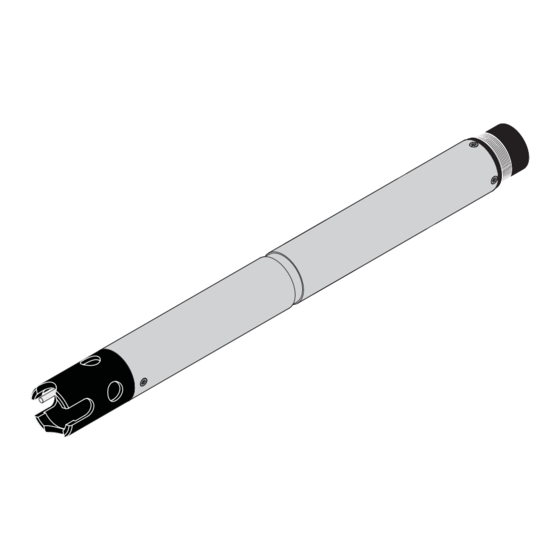
® AmmoLyt 700 IQ ® Structure of the AmmoLyt 700 IQ ammonium sensor ® Fig. 1-2 Structure of the AmmoLyt 700 IQ ammonium sensor Protective hood Temperature probe ® AmmoLyt combination electrode ® with AmmoLyt NHA reference electrode ® and AmmoLyt NHA/AT replacement electrode (electrode not contained in the scope of delivery). -
Page 7: Safety
® AmmoLyt 700 IQ Safety This component operating manual contains special instructions that ® must be followed in the operation of the AmmoLyt 700 IQ ammonium sensor. Thus, it is essential to read this component operating manual before carrying out any work using this sensor. In addition to this manual, the S chapter of the IQ S system operating... -
Page 8: Authorized Use
The specified temperature (chapter 8 T ) must be ECHNICAL DATA maintained during the operation and transport of the sensor. Protect the sensor, particularly against frost or overheating. Caution The sensor may only be opened by specialists authorized by WTW. 2 - 2 ba75353e05 03/2006... - Page 9 ® AmmoLyt 700 IQ Safe operation If safe operation is no longer possible, the sensor must be taken out of operation and secured against inadvertent operation. Safe operation is no longer possible if the sensor: ! has been damaged in transport ! has been stored under adverse conditions for a lengthy period of time ! is visibly damaged...
- Page 10 ® AmmoLyt 700 IQ 2 - 4 ba75353e05 03/2006...
-
Page 11: Commissioning
Do not suspend the sensor on the sensor connection cable. Use an armature or electrode holder. Information on this and other IQ S ENSOR accessories is given in the WTW catalog and on the Internet. ba75353e05 03/2006 3 - 1... - Page 12 ® AmmoLyt 700 IQ Connecting the sensor Take the protective caps off the plug connections of the sensor to the sensor and the SACIQ sensor connection cable, and keep them safe. connection cable Plug the jack of the SACIQ sensor connection cable onto the plug head connector of the sensor.
-
Page 13: Commissioning / Getting The Sensor Ready For Measuring
® AmmoLyt 700 IQ Commissioning / Getting the sensor ready for measuring Mounting the Unscrew the protective hood from the sensor. combination electrode Pull off the blind plug from the plug head socket of the sensor. Prepare the combination electrode to be mounted in the sen- sor. - Page 14 ® AmmoLyt 700 IQ ® Grease the two sealing rings (1) of the AmmoLyt electrode using the grease from the tube supplied. Unscrew the protection cap from the plug head of the reference electrode. Screw the reference electrode into the plug head socket of the sensor.
- Page 15 ® AmmoLyt 700 IQ Push the unit into the sensor up to the stop. Caution Push the electrode into the sensor right up to the stop so that the connection is watertight. Leaks could lead to the destruction of the sensor. Screw the protective hood onto the sensor.
-
Page 16: Carrying Out The Settings For The Sensor On The Terminal Of The Iq Sensor Net System
® AmmoLyt 700 IQ Carrying out the settings for the sensor on the termi- nal of the IQ S system ENSOR The following settings can be carried out for the sensor: Menu item Possible settings Explanations ! NH4 Measuring mode The citation form of the mass concentrati- on or the voltage of the electrode. - Page 17 The concentration of the test sample determined in a reference procedure must be entered. ! 2-point calibration using any two WTW ! 2 point stand. (3) standard solutions. The concentration of the standard solutions must be ente- red.
- Page 18 ® AmmoLyt 700 IQ Menu item Possible settings Explanations Temp. adjustment -1.5 °C ... +1.5 °C The temperature compensation function enables the temperature sensor to be ba- lanced against a reference temperature measurement (displacement of the zero point by ±1.5 °C). Notes: ! Due to the thermal capacity of the sen- sor, it is necessary to place it in a con-...
- Page 19 ® AmmoLyt 700 IQ Fig. 3-2 140 - Settings of sensors and diff. sensors Confirm the selection with The settings of the sensor are displayed. Fig. 3-3 140 - Settings of sensors and diff. sensors Make the sensor settings with and confirm each of them with Select the Save and quit menu item with...
- Page 20 ® AmmoLyt 700 IQ 3 - 10 ba75353e05 03/2006...
-
Page 21: Calibration And Measuring
® AmmoLyt 700 IQ Calibration and measuring Calibration and measuring Calibration 4.1.1 General information Why calibrate? When an ammonium electrode is operated its characteristic curve changes with the course of time. The characteristic curve is generally characterized by the slope and the axis intercept. The characteristic curve is the base for calculating the measured value from the electrode voltage. -
Page 22: Overview Of The Calibration Procedures
® Calibration and measuring AmmoLyt 700 IQ 4.1.2 Overview of the calibration procedures ® For ammonium measurements with the AmmoLyt 700 IQ sensor, the following calibration procedures can be selected: 1 point standard (1) 1-point calibration in a standard solution. 1 point ref. -
Page 23: Calibration In Practice
® AmmoLyt 700 IQ Calibration and measuring 4.1.3 Calibration in practice Initial calibration The first calibration (initial calibration) is especially important as it is the reference point for all other calibrations (following calibrations). An initial calibration is required each time an electrode is commissio- ned. - Page 24 ® Calibration and measuring AmmoLyt 700 IQ Optimum calibration of an electrode Fig. 4-1 Sequence of calibrations 4 - 4 ba75353e05 03/2006...
-
Page 25: General Course Of A Calibration
® AmmoLyt 700 IQ Calibration and measuring 4.1.4 General course of a calibration Preparatory activities An optimum calibration result is possible by, ! before calibrating, – conditioning the sensor in the ES/NH4_ISA-10 standard solution with 10 mg/l NH4-N for approx. 10 minutes –... - Page 26 ® Calibration and measuring AmmoLyt 700 IQ Fig. 4-3 200 - Calibrate sensor Confirm with The following display (or similar, depending on the selected calibration procedure) appears: Fig. 4-4 200 - Calibrate sensor The further course depends on the respective calibration pro- cedure.
- Page 27 ® AmmoLyt 700 IQ Calibration and measuring Note The sensor determines a stable measured value with each measure- ment during the course of a calibration. The display shows a continua- tion display and the current electrode voltage in mV. After calibrating, the following display appears: Fig.
-
Page 28: Calibration Procedure, 1 Point Standard (1)
® Calibration and measuring AmmoLyt 700 IQ 4.1.5 Calibration procedure, 1 point standard (1) The 1 point standard (1) 1-point calibration is carried out using one standard solution. Note Determine the potassium content of the sample (see section 4.2.2). Activate the Potassium compens. function and adjust the potassium content (see section 3.4). -
Page 29: Calibration Procedure, 1 Point Ref. (2)
® AmmoLyt 700 IQ Calibration and measuring 4.1.6 Calibration procedure, 1 point ref. (2) The 1 point ref. (2) 1-point calibration is carried out with the sample and in two main steps, each of which is started with c. Note Determine the calibration value and take the sample before the start of the aeration in the aeration tank. - Page 30 ® Calibration and measuring AmmoLyt 700 IQ Sampling and You have to be in the measured value display to continue the calibra- determining the tion. Continue with sampling and determining the reference concentra- reference concentration tion as follows. Take a sample. Note The ammonium content has to be determined immediately after taking the sample as the ammonium content changes very quickly due to the...
- Page 31 ® AmmoLyt 700 IQ Calibration and measuring Citation form of ref. conc. If necessary select the citation NH4(0.1..129.0mg/l) form with NH4(1..1290mg/l) Confirm with NH4N(0.1..100.0mg/l) NH4N(1..1000mg/l) Input reference concentration Confirm with Value determined Value of ref. concentration If necessary set the reference x mg/l NH4-N concentration determined with Confirm with...
- Page 32 ® Calibration and measuring AmmoLyt 700 IQ Operating steps during Displays Explanation calibration Unscrew protective hood. Prepare the sensor as described. Clean and rinse sensor incl. elec- After completing the operating trode and protective hood, then steps confirm with reassemble them. Cal.: 2 POINT STANDARD (3) Confirm with Have standard 1 ready for calibra-...
-
Page 33: Calibration Procedure, Simple Std. Add. (4)
® AmmoLyt 700 IQ Calibration and measuring Displays Explanation Cal.: 2 POINT STANDARD (3) Confirm with Calibration values for standard 2 determined Calibration successful The values for Conc. (NH4-N), Conc. (NH4-N) x mg/l Slope and Drift voltage are dis- Slope y mV played. - Page 34 ® Calibration and measuring AmmoLyt 700 IQ Concentration and The concentration and quantity of the standard solution to be added quantity of standard depend on the measuring range expected. They can be determined by solution means of the following diagram. The requirements for the simple stan- dard addition are automatically met while doing so.
- Page 35 ® AmmoLyt 700 IQ Calibration and measuring Entry of volumes The volume of standard to be added in this calibration procedure has to be entered on the terminal of the IQ S with an accuracy ENSOR of 1/10 ml. Therefore, the volume has to be rounded up or down accor- dingly.
-
Page 36: Calibration Procedure, Double Std. Add. (5)
® Calibration and measuring AmmoLyt 700 IQ 4.1.9 Calibration procedure, Double std. add. (5) This calibration with double standard addition is carried out in the test sample while adding standard with a certain concentration in two steps. The volumes of test sample and standard have to be dosed exactly. The following appliances are suitable for dosing: ! Measuring cylinder to determine the volume of the sample ! Pipette to exactly dose the standard... - Page 37 ® AmmoLyt 700 IQ Calibration and measuring Note Make sure the citation form is correct for all specifications of the con- centration. Operating steps during Display Explanation calibration Cal.: DOUBLE STD. ADD. (5) Confirm with Have test sample ready for cali- bration Input sample volume If necessary select the volume of...
-
Page 38: Calibration Result
® Calibration and measuring AmmoLyt 700 IQ Display Explanation Cal.: DOUBLE STD. ADD. (5) Confirm with Reference voltage determined after first standard addition Add standard to sample Confirm with * Wait for a stable measured Confirm with value. The measurement begins. Cal.: DOUBLE STD. - Page 39 ® AmmoLyt 700 IQ Calibration and measuring A calibration can have the following results: Possible results of the Display after the calib- Log book entries calibration ration (meaning/actions) Measured value display Sensor was successfully calibrated. Slope and drift potential are within the valid range.
- Page 40 ® Calibration and measuring AmmoLyt 700 IQ Calibration history Calibration data of the initial calibra- tion. List with calibration data of the last cali- brations Fig. 4-6 330 - Calibration history of selected sensor The calibration history contains the following information: Date Date of the calibration S(*)
-
Page 41: Measuring
® AmmoLyt 700 IQ Calibration and measuring Measuring Submerse the sensor with the mounted combination electrode in the sample. Read the measured value on the terminal of the IQ S ENSOR system. Note Please pay attention to: ! the minimum immersion depth of the sensor (> 70 mm) ! the measuring range of the electrode used (see operating manual of the electrode). -
Page 42: Potassium Compensation
The compensation can, e. g. be performed using the superior process control engineering. Note For details, please refer to WTW GmbH. 4.2.2 Potassium compensation Measuring ammonium in the presence of potassium leads to increased... -
Page 43: Further Influences On The Measured Value
NH4-N value for different potassium contents. The characteristic curve with the optimum potassium compensation corresponds to the charac- teristic curve without any potassium content. c (NH4-N) [mg/l] displayed by AmmoLyt 700 IQ 1000 1000 0 mg/l K real c (NH4-N) [mg/l]... - Page 44 ® Calibration and measuring AmmoLyt 700 IQ 4 - 24 ba75353e05 03/2006...
-
Page 45: Maintenance And Changing The Electrode
® AmmoLyt 700 IQ Maintenance and changing the electrode ® The AmmoLyt 700 IQ ammonium sensor is maintenance-free. Warning Contact with the sample can be dangerous for the user! Depen- ding on the type of sample, suitable protective measures must be taken (protective clothing, protective goggles, etc.). - Page 46 ® AmmoLyt 700 IQ Replacing the electrode If it is necessary to replace an electrode, proceed as follows: Unscrew the protective hood from the sensor. Use the protective hood as a tool to lever out the electrode. Carefully pull out the electrode until the plug head screwed fit- ting can be seen.
- Page 47 ® AmmoLyt 700 IQ Screw in a new electrode. Push the unit into the sensor up to the stop. Screw the protective hood onto the sensor. ba75353e05 03/2006 5 - 3...
-
Page 48: Disposal
® AmmoLyt 700 IQ Calibrate the sensor and the electrode with the measuring sys- tem (see section 4.1 C ALIBRATION Disposal Sensor We recommend disposing of the sensor as electronic refuse. Electrodes If no official regulations apply to the contrary, used and defective elec- trodes can be treated as household waste. -
Page 49: Replacement Parts And Accessories
® AmmoLyt 700 IQ Replacement parts and accessories Sensor and electrodes Ammonium sensor Model Order no. ® AmmoLyt 700 IQ 107002 Ammonium electrodes Model Order no. ® Reference electrode AmmoLyt 107004 ® Exchange electrode AmmoLyt NHA/AT 107006 General accessories Protective hood Designation Order no. - Page 50 ® AmmoLyt 700 IQ Cleaning system Model Order no. CH Cleaning Head 900107 MIQ/CHV Valve Module 900109 Note Information on other IQ S accessories is given in the WTW ENSOR catalog and on the Internet. 6 - 2 ba75353e05 03/2006...
-
Page 51: What To Do If
® AmmoLyt 700 IQ What to do if... No measured value Cause Remedy – Sensor not connected – Connecting the sensor – Unknown – Look in the log book Measurement does not Cause Remedy function – Electrode not connected – Connect electrode –... - Page 52 ® AmmoLyt 700 IQ System cannot be Cause Remedy calibrated – Slope of the electrode not – Condition the electrode within tolerance (see section – If the slope is still outside the 4.1.10) tolerance: Replace the elec- trode – Drift of the electrode too high –...
-
Page 53: Technical Data
® AmmoLyt 700 IQ Technical data Technical data Measuring properties Measuring principle Potentiometric measurement with an ammonium-selective combina- tion electrode; Integrated microprocessor electronics, shielded 2-wire connection for power and data transmission. Measuring ranges and Measuring Measuring range Resolution resolutions mode 0.1 ... -
Page 54: General Features
® Technical data AmmoLyt 700 IQ Depth of immersion min. 70 mm; max. 2 m depth Operating position pendulous to horizontal Field of application Controlling / monitoring in the aeration tank of waste water treatment plants, water and waste water monitoring General features Dimensions 40,0... -
Page 55: Electrical Data
® AmmoLyt 700 IQ Technical data Electrical data Nominal voltage Max. 24 VDC via the IQ S (for more ENSOR details, see T ECHNICAL DATA chapter of the IQ S ENSOR system operating manual) Power consumption 0.2 W Protective class ba75353e05 03/2006 8 - 3... - Page 56 ® Technical data AmmoLyt 700 IQ 8 - 4 ba75353e05 03/2006...
-
Page 57: Indexes
EC1351 Sensor could not be calibrated, Sensor blocked for measurement * Check calibration conditions and calibration standard * View calibration history * Service sensor immediately (see operating manual) ES1351 Component hardware defective * Contact WTW ba75353e05 03/2006 9 - 1... -
Page 58: Info Messages
® AmmoLyt 700 IQ 9.1.2 Info messages Message code Message text IC1351 Sensor has been successfully calibrated * For calibration data, see calibration history Status info The status info is a coded piece of information on the current status of a sensor.
Need help?
Do you have a question about the AmmoLyt 700 IQ and is the answer not in the manual?
Questions and answers