
Related Manuals for wtw FDO 700 IQ


Summary of Contents for wtw FDO 700 IQ
- Page 1 Operating manual FDO 700 IQ FDO 700 IQ SW FDO 700 IQ FDO 700 IQ SW Optical IQ S D.O. sensor ENSOR ba75586e03 05/2009...
- Page 2 FDO 700 IQ (SW) Accuracy when going to The use of advanced technology and the high quality standard of our press instruments are the result of continuous development. This may result in differences between this operating manual and your instrument.
- Page 3 ........3-3 FDO 700 IQ (SW) setting table ....3-3 Measuring / Operation .
- Page 4 Contents FDO 700 IQ (SW) Technical data ....... 7-1 Measuring characteristics ......7-1 Application conditions .
-
Page 5: Overview
FDO 700 IQ (SW) Overview Overview How to use this component operating manual Structure of the IQ Sensor Net Operating Manual IQ S ENSOR operating manual System Operating Manual (Ring Binder) IQ Sensor MIQ Module MIQ Terminal Operating Operating Operating... -
Page 6: Structure Of The Fdo 700 Iq (Sw)
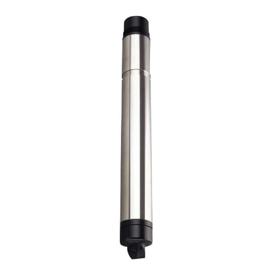
Overview FDO 700 IQ (SW) Structure of the FDO 700 IQ (SW) Fig. 1-2 Structure of the D. O. sensor (example: FDO 700 IQ) Shaft Plug head connector Fixing ring Sensor membrane Sensor cap with memory chip Gold-plated contact pins for memory chip... -
Page 7: Recommended Fields Of Application
FDO 700 IQ (SW) Overview Intelligent membrane For each membrane the individual calibration values are determined by (IQMC technology) a factory calibration process and stored on the memory chip of the sensor cap, ensuring maximum accuracy over the whole lifetime of the sensor. - Page 8 Overview FDO 700 IQ (SW) 1 - 4 ba75586e03 05/2009...
-
Page 9: Safety Instructions
Safety instructions This component operating manual contains special instructions that must be followed during the operation of the FDO 700 IQ (SW) D.O. sensor. Thus, it is essential to read this component operating manual before carrying out any work using this sensor. In addition to this... -
Page 10: Authorized Use
Safety instructions FDO 700 IQ (SW) Authorized use The authorized use of the FDO 700 IQ (SW) comprises its use as a D.O. sensor in the IQ S ENSOR Please observe the technical specifications according to chapter 7 . Only operation according to the instructions in this ECHNICAL DATA operating manual is authorized. - Page 11 FDO 700 IQ (SW) Safety instructions Safe operation If safe operation is no longer possible, the sensor must be taken out of operation and secured against inadvertent operation. Safe operation is no longer possible if the sensor: has been damaged in transport...
- Page 12 Safety instructions FDO 700 IQ (SW) 2 - 4 ba75586e03 05/2009...
-
Page 13: Commissioning
FDO 700 IQ (SW) with SC FDO 700 sensor cap Operating manual. IQ S system requirements ENSOR Software statuses of the The operation of the FDO 700 IQ (SW) requires the following software controller and terminal versions in the IQ S ENSOR components MIQ/C184 (XT) Controller software: Version 2.66 or higher... - Page 14 Note Do not suspend the sensor on the sensor connection cable. Use a sensor holder or an armature. Information on this and other IQ S accessories is given in the WTW catalog and on the ENSOR Internet. Connecting the sensor...
-
Page 15: Measuring
ENSOR follows in the list of sensors: Type designation of the sensor cap ("SC FDO 700") Series number of the FDO 700 IQ or FDO 700 IQ SW sensor Commissioning steps Pull the protective cap off the sensor. If required, assign a user-defined name to the sensor (see relevant IQ S system operating manual). - Page 16 Commissioning FDO 700 IQ (SW) Setting Selection/values Explanation Calibration Factory Determines which calibration data the calibration measured value calculation will be based on. The active calibration is displayed in the User calibration calibration history. active The selection, User calibration is only...
- Page 17 . Then navigate to the setting menu (setting table) of the sensor. The exact procedure is described in the relevant IQ S ENSOR system operating manual. Note For information on oxygen measurement in solutions that contain salt, see WTW application report no. 1193118. ba75586e03 05/2009 3 - 5...
- Page 18 Commissioning FDO 700 IQ (SW) 3 - 6 ba75586e03 05/2009...
-
Page 19: Measuring / Operation
EPLACEMENT PARTS AND ACCESSORIES Function check and user calibration 4.2.1 General information Factory calibration The FDO 700 IQ (SW) is factory calibrated. In the recommended application (see section 1.3 R ), the ECOMMENDED FIELDS OF APPLICATION measuring characteristics of the sensor cap remain stable for the specified service life. -
Page 20: Function Check
Measuring / Operation FDO 700 IQ (SW) 2 cm With air temperatures under 5 °C we recommend performing the function check and user calibration not in air but in air-saturated water that has a higher temperature. You obtain air-saturated water by pouring water several times in and out of two vessels so that it sparkles. - Page 21 FDO 700 IQ (SW) Measuring / Operation Evaluation The evaluation is based on the accuracy required by the user. Together with the target value (100 %) this results in a scope for the function check. If the measured value is within the scope, no cleaning or user calibration is required.
-
Page 22: User Calibration
ENSOR Switch to the measured value display with and select the FDO 700 IQ (SW) sensor. Press The next step switches on the maintenance condition for the sensor. A corresponding message appears on the display. Confirm the note with The maintenance condition is active. - Page 23 FDO 700 IQ (SW) Measuring / Operation Canceling the user As long as the determination of the calibration data has not yet been calibration started (step 5), you can quit the calibration routine with The running determination of calibration data (after pressing...
-
Page 24: Calibration History
Measuring / Operation FDO 700 IQ (SW) 4.2.4 Calibration history Calibration history (available in the IQ S systems ENSOR 184 XT and 2020 XT Currently active only) calibration Chronological list of the last user calibrations Fig. 4-1 Calibration historyFDO 700 IQ (SW) -
Page 25: Reactivating Previous Calibration Data
Measuring / Operation 4.2.5 Reactivating previous calibration data The FDO 700 IQ (SW) enables you to reactivate the last valid user calibration or the factory calibration. Thus you can immediately go on measuring if a calibration procedure failed or you suspect that the calibration conditions were not optimally met. - Page 26 Measuring / Operation FDO 700 IQ (SW) 4 - 8 ba75586e03 05/2009...
-
Page 27: Maintenance, Cleaning, Replacement Parts
FDO 700 IQ (SW) Maintenance, cleaning, replacement parts Maintenance, cleaning, replacement parts General maintenance notes Warning Contact with the sample can be dangerous for the user! Depending on the type of sample, suitable protective measures must be taken (protective clothing, protective goggles, etc.). -
Page 28: Handling Of The Sensor Cap
Maintenance, cleaning, replacement parts FDO 700 IQ (SW) Handling of the sensor cap Despite its exterior robustness, the sensor is an optical high precision instrument. Therefore, special care should be taken when doing any maintenance or cleaning work: Dirt and moisture under the sensor cap can affect the functioning and shorten the service life of the sensor cap. -
Page 29: Cleaning The Sensor
FDO 700 IQ (SW) Maintenance, cleaning, replacement parts Mounting the sensor Check the front surface of the sensor for absolute cleanness and clean it if necessary (see section 5.4.1). Thoroughly clean the thread of the fixing ring. Place the new sensor cap on the sensor so that the temperature sensor fits into the hole inside the sensor cap (see figure opposite). -
Page 30: Head
Maintenance, cleaning, replacement parts FDO 700 IQ (SW) 5.4.2 Interior cleaning of sensor cap and sensor head If moisture or dirt have penetrated under the sensor cap, e.g. because the sensor cap is damaged, you can make the sensor ready for... -
Page 31: Replacement Parts And Accessories
Active valve module (does not MIQ/CHV PLUS 480018 require a free relay output in the IQ S system) ENSOR Note Information on other IQ S accessories is given in the WTW ENSOR catalog and on the Internet. ba75586e03 05/2009 5 - 5... - Page 32 Maintenance, cleaning, replacement parts FDO 700 IQ (SW) 5 - 6 ba75586e03 05/2009...
- Page 33 FDO 700 IQ (SW) What to do if... What to do if... Sensor does not appear Cause Remedy in the measured value – Sensor cap not mounted or – Sensor cap (see section 5.3) display and list of defective sensors –...
- Page 34 What to do if... FDO 700 IQ (SW) Measured value invalid Cause Remedy ( "----" displayed) – User calibration unsuccessful. – As a temporary measure to The sensor is blocked for quickly restore the readiness measurement. for service: Activate the factory calibration (see section 4.2.5)
-
Page 35: Technical Data
FDO 700 IQ (SW) Technical data Technical data Measuring characteristics Measuring principle Optical measurement based on photoluminescence. Measuring ranges and D. O. partial pressure 0 ... 400 hPa resolutions Measuring Adjustable measuring range Resolution mode D. O. 0 ... 20.00 mg/l 0.01 mg/l... -
Page 36: Application Conditions
Technical data FDO 700 IQ (SW) Temperature In the range - 5 °C ... + 50 °C (23 ... 122 °F) compensation Calibration procedures, Factory calibration by means of IQMC (Intelligent Membrane Calibration) procedure. User calibration possible in water vapor- saturated air or air-saturated water. -
Page 37: General Data
Connection technique Connection via SACIQ (SW) sensor connection cable Material Shaft: – FDO 700 IQ V4A stainless steel 1.4571 – FDO 700 IQ SW Plug head connector housing Sensor head POM and PVC Sensor cap PMMA, PVC and silicone ®... -
Page 38: Electrical Data
Technical data FDO 700 IQ (SW) Automatic sensor Monitoring of the membrane function monitoring (SensCheck function) Instrument safety Applicable norms – EN 61010-1 – UL 3111-1 – CAN/CSA C22.2 No. 1010.1 Electrical data Nominal voltage max. 24 VDC via the IQ S... -
Page 39: Indexes
This chapter contains a list of all the message codes and related message texts that can occur in the log book of the IQ S ENSOR system for the FDO 700 IQ (SW) sensor. Note Information on the contents and structure of the log book, and how to... -
Page 40: Info Messages
Indexes FDO 700 IQ (SW) Message code Message text EC8334 Sensor could not be calibrated, sensor blocked for measurement Cause: instable signal * Check temperature adjustment * Check calibration conditions (see operating manual) * Repeat calibration EC9334 Calibration error, measurement disabled... -
Page 41: Status Info
FDO 700 IQ (SW) Indexes Status info The status info is a piece of coded information about the current state of a sensor. Each sensor sends this status info to the controller. The status info of sensors consists of 32 bits, each of which can have the value 0 or 1. - Page 42 Indexes FDO 700 IQ (SW) 8 - 4 ba75586e03 05/2009...
Need help?
Do you have a question about the FDO 700 IQ and is the answer not in the manual?
Questions and answers