Table of Contents
Advertisement
Quick Links
Download this manual
See also:
Operating Manual
Advertisement
Table of Contents

Subscribe to Our Youtube Channel
Related Manuals for wtw AmmoLyt Plus 700 IQ


Summary of Contents for wtw AmmoLyt Plus 700 IQ
- Page 1 OPERATING MANUAL ba75651e07 04/2016 ® AmmoLyt 700 IQ MODULAR COMBINATION SENSOR FOR AMMONIUM AND NITRATE...
- Page 2 Copyright © 2016 Xylem Analytics Germany GmbH Printed in Germany.
-
Page 3: Table Of Contents
®Plus AmmoLyt 700 IQ Contents Contents Overview ........5 How to use this component operating manual . - Page 4 ®Plus Contents AmmoLyt 700 IQ 4.3.2 Result of the check ..... . 30 4.3.3 Result of the calibration ....30 Sensor history .
-
Page 5: Overview
®Plus AmmoLyt 700 IQ Overview Overview How to use this component operating manual Structure of the IQ Sensor Net Operating Manual IQ S ENSOR operating manual System Operating Manual (Ring Binder) IQ Sensor MIQ Module MIQ Terminal Operating Operating Operating Manual Manual Manual... -
Page 6: Structure Of The Sensor Ammolyt ®Plus 700 Iq
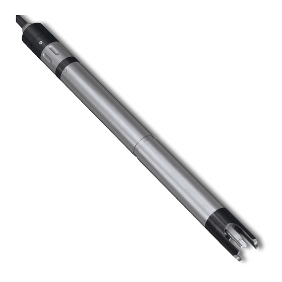
®Plus Overview AmmoLyt 700 IQ ®Plus Structure of the sensor AmmoLyt 700 IQ ®Plus Fig. 1-2 Structure of the sensor AmmoLyt 700 IQ Protective hood Temperature sensor Electrode support with electrodes (sample equipment) Sensor shaft Plug head connector ®Plus Electrodes For a AmmoLyt 700 IQ sensor ready to measure, a jointly used reference electrode and at least one ion sensitive electrode for the... -
Page 7: Recommended Fields Of Application
®Plus AmmoLyt 700 IQ Overview ®Plus Operating modes and Due to its modular structure, the AmmoLyt 700 IQ can be adapted electrode equipment to various requirements (see table on the following page). Notes on the table: The reference electrode has an extra receptacle marked by a recess. The ion sensitive electrodes can be mounted in the remaining three receptacles in any order. - Page 8 ®Plus Overview AmmoLyt 700 IQ ments D. O. measurement in the aeration tank of waste water treatment plants and enables an efficient process control of nitrogen removal. More detailed information on measuring with ion sensitive electrodes is given in the primer, I ON SELECTIVE MEASURE MENT IN ONLINE ANALYSIS ba75651e07...
-
Page 9: Safety
®Plus AmmoLyt 700 IQ Safety Safety Safety information 2.1.1 Safety information in the operating manual This operating manual provides important information on the safe oper- ation of the product. Read this operating manual thoroughly and make yourself familiar with the product before putting it into operation or working with it. -
Page 10: Safe Operation
®Plus Safety AmmoLyt 700 IQ Safe operation 2.2.1 Authorized use ®Plus The authorized use of the AmmoLyt 700 IQ consists of its use as a sensor in the IQ S . Only the operation and running of the ENSOR sensor according to the instructions and technical specifications given in this operating manual is authorized (see chapter 7 T ECHNICAL DATA Any other use is considered unauthorized. -
Page 11: Commissioning
®Plus AmmoLyt 700 IQ Commissioning Commissioning Scopes of delivery ®Plus The AmmoLyt 700 IQ sensor is provided in sets for different mea- surement requirements. Each set contains the following components: ®Plus Unequipped sensor AmmoLyt 700 IQ. The electrode recepta- cles are closed with blind plugs ... -
Page 12: Notes On The Handling Of The Electrodes
®Plus Commissioning AmmoLyt 700 IQ MIQ/MC Controller software: Version 2.83 or higher MIQ/T 2020 (PLUS) Terminal software: Version 2.91 or higher IQ-LabLink procedure Software: Version 3.06 to ver- ®Plus (AmmoLyt 700 IQ sion 3.25 Notes on the handling of the electrodes ®Plus The electrodes of the AmmoLyt 700 IQ sensor were developed for... -
Page 13: Reference Electrode
®Plus AmmoLyt 700 IQ Commissioning 3.3.2 Reference electrode Commissioning Reference electrode Junction Watering cap Sealing ring Fig. 3-1 Reference electrode with storing aids In the delivery condition, the electrode is equipped with a watering cap and a nut that protects the screw-in thread. The watering cap contains 3 mol/l potassium chloride solution. -
Page 14: Measurement Electrodes And Compensation Electrodes
®Plus Commissioning AmmoLyt 700 IQ 3.3.3 Measurement electrodes and compensation electrodes Commissioning Electrode Watering cap Sealing ring Fig. 3-2 Measurement or compensation electrode with storing aids In the delivery condition, each electrode is equipped with a watering cap and a nut that protects the screw-in thread. Prior to installation, first remove the watering cap and, using the special hexagon key, unscrew the electrode from the nut. -
Page 15: Getting The Sensor Ready For Measuring
®Plus AmmoLyt 700 IQ Commissioning Getting the sensor ready for measuring 3.4.1 Equipping the sensor with electrodes NOTE The sensor can be damaged by dirt and moisture. Before mounting the electrodes make sure the area behind the sealing ring of the electrodes ®Plus and the receptacle are dry and clean. -
Page 16: Mounting The Protective Hood
®Plus Commissioning AmmoLyt 700 IQ The measurement and compensation electrodes can be mounted in the remaining three receptacles in any order. During installation make sure the area behind the sealing ring of the electrode and the receptacle are absolutely dry and clean. ... - Page 17 ®Plus AmmoLyt 700 IQ Commissioning Loosen the coupling ring (1) of the protective hood. Push the protective hood on the sensor as far as it will go. Tighten the coupling ring of the protective hood. Cleaning the protective The coupling ring of the protective hood can be taken apart for cleaning hood purposes (see section 6.2 E XTERIOR CLEANING...
- Page 18 ®Plus Commissioning AmmoLyt 700 IQ Connecting the sensor to the sensor SACIQ connection cable Fig. 3-5 Connect the sensor Take the protective caps off the plug connections of the sensor and the SACIQ sensor connection cable, and keep them safe. Plug the socket of the SACIQ sensor connection cable onto the plug head connector of the sensor.
-
Page 19: Settings
®Plus AmmoLyt 700 IQ Commissioning Settings 3.5.1 General information ®Plus Automatic electrode The AmmoLyt 700 IQ software automatically recognizes the built- recognition in electrodes and checks the equipment for validity. Depending on the equipment, the following sensors can be displayed in the list of sen- sors: sensor Designation... -
Page 20: Setting Table Ammolyt+ (Ammonium Sensor)
®Plus Commissioning AmmoLyt 700 IQ 3.5.2 Setting table AmmoLyt+ (ammonium sensor) Menu item Selection/Values Explanations NH4-N Measuring mode Citation form of the mass concentration or voltage of the electrode. NH4 mV AutoRange Measuring range 2 measuring ranges can be selected. (Measuring mode: With AutoRange, the instrument ... - Page 21 ®Plus AmmoLyt 700 IQ Commissioning Menu item Selection/Values Explanations If the sensor is equipped with a potassium electrode: hide VARiON K hide (standard setting): The potassium electrode is not displayed show as an extra sensor in the measured value display.
-
Page 22: Setting Table Ammolyt+K (Potassium Sensor)
®Plus Commissioning AmmoLyt 700 IQ Menu item Selection/Values Explanations Temp. adjustment -1.5 °C ... +1.5 °C The temperature compensation function (only with Measuring enables the temperature sensor to be mode: NH4-N or NH4) balanced against a reference temperature measurement (displacement of the zero point by ±1.5 °C). - Page 23 ®Plus AmmoLyt 700 IQ Commissioning Menu item Selection/Values Explanations -2000 ... 2000 mV Measuring range Fixed range Measuring mode: mV Temperature mode °C Unit of the measured temperature value (only with Measuring (Celsius, Fahrenheit). °F mode: K (mg/l)) Temp.
-
Page 24: Matrix Adjustment, Check And Calibration
®Plus Matrix adjustment, check and calibration AmmoLyt 700 IQ Matrix adjustment, check and calibration General information ®Plus Calibration free The AmmoLyt 700 IQ sensor is immediately ready to measure operation after being equipped with electrodes. For precise measurements, it is only necessary to adjust the electrodes to the sample matrix ("matrix adjustment"). -
Page 25: Matrix Adjustment
®Plus AmmoLyt 700 IQ Matrix adjustment, check and calibration Matrix adjustment 4.2.1 General information on matrix adjustment This procedure adjusts the value measured directly in the test sample to an independently determined reference value ("lab value"). To deter- mine the reference values, a sample is taken from the measuring solu- tion and the relevant concentrations are measured (e.g. -
Page 26: Result Of The Matrix Adjustment
®Plus Matrix adjustment, check and calibration AmmoLyt 700 IQ Matrix adjustment with After installing a new or different electrode you have to zero the elec- zeroing trode to facilitate a long-term evaluation. Details on zeroing, see sec- tion 4.1. Ammonium has to be determined immediately after taking the sam- Practical instructions ple as its concentration changes very quickly due to the micro organ- isms that are present. -
Page 27: Special Functions
®Plus AmmoLyt 700 IQ Matrix adjustment, check and calibration Actions for error elimination are given in the Online help and in chapter 8 W ..HAT TO DO IF Sensor history The data of the matrix adjustment are available in the Sensor history (see section 4.4 S ENSOR HISTORY 4.2.4 Special functions... - Page 28 ®Plus Matrix adjustment, check and calibration AmmoLyt 700 IQ ®Plus The long term stable VARiON electrodes are calibra- tion-free in the recommended application. A check in stan- dard solutions is only of significance if all basic conditions (cleanness, conditioning etc.) are strictly kept. Calibrating the sensor is neither necessary nor recom- mended.
- Page 29 ®Plus AmmoLyt 700 IQ Matrix adjustment, check and calibration Standard solutions For the procedures CHECK or CALIBRATION, the following standard solutions in the following order: ® VARiON /ES-2 (high concentration) ® VARiON /ES-1 (low concentration). These standard solutions contain all ion types that come into question (ammonium and potassium) and are especially adapted to the ®Plus AmmoLyt...
-
Page 30: Result Of The Check
®Plus Matrix adjustment, check and calibration AmmoLyt 700 IQ Make sure there are no air bubbles in front of the electrode mem- brane. Conditioning times: During the conditioning steps, all relevant elec- trode voltages are indicated on the display. Thus you can observe the conditioning process. -
Page 31: Sensor History
®Plus AmmoLyt 700 IQ Matrix adjustment, check and calibration Actions for error elimination are given in chapter 8 W HAT TO ..DO IF Sensor history The result of the calibration is available in the Sensor history (see sec- tion 4.4 S ENSOR HISTORY Sensor history The data of the calibration procedures and matrix adjustments are... - Page 32 ®Plus Matrix adjustment, check and calibration AmmoLyt 700 IQ In the measured value display, select the sensor with <> and confirm with <OK>. The Anzeige/Optionen menu pops up. Display the individual calibration histories. Last electrode zeroing via matrix adjustment Chronological list of the last matrix adjustments Fig.
- Page 33 ®Plus AmmoLyt 700 IQ Matrix adjustment, check and calibration If the compensation electrode is displayed as an extra sensor, the calibration history of the compensation elec- trode can be viewed in the sensor menu of this sensor. Log book messages are displayed with the main sensor. The IQ S does not keep an extra log book for ENSOR...
-
Page 34: Measuring
®Plus Measuring AmmoLyt 700 IQ Measuring Measurement operation Note the data given in section 9.2 A , especially PPLICATION CONDITIONS the minimum immersion depth of the sensor (> 50 mm with mounted protective hood). NOTE Greases, oils, certain tensides and similar substances can shorten the operational lifetime of the electrodes. -
Page 35: Maintenance And Electrode Exchange
®Plus AmmoLyt 700 IQ Maintenance and electrode exchange Maintenance and electrode exchange General maintenance instructions WARNING Contact with the sample can be dangerous for the user! Depending on the type of sample, suitable protective measures must be taken (protective clothing, protective goggles, etc.). Maintenance condition We recommend to switch on the maintenance condition each time the sensor is taken out of the measuring position. - Page 36 ®Plus Maintenance and electrode exchange AmmoLyt 700 IQ Unscrew the sensor from the SACIQ sensor connection cable. Always place a protective cap on the plug head of the sensor and on the SACIQ sensor connection cable so that no moisture or dirt can get into the contacting surfaces.
-
Page 37: Exchanging The Electrodes
®Plus AmmoLyt 700 IQ Maintenance and electrode exchange Exchanging the electrodes NOTE The sensor can be damaged by dirt and moisture. Each time before dis- mantling an electrode carefully clean the area around the electrodes (section 6.2). Before mounting an electrode make sure the area behind the sealing ring of the electrode and the receptacle are dry and clean. -
Page 38: Replacement Parts And Accessories
®Plus Replacement parts and accessories AmmoLyt 700 IQ Replacement parts and accessories Electrodes Exchange electrodes Description Model Order no. ®Plus Reference electrode VARiON 107042 ®Plus Ammonium electrode VARiON 107044 ®Plus Potassium electrode VARiON 107046 Storing equipment Description Model Order no. 250 ml potassium chloride KCl-250 109705... - Page 39 ®Plus AmmoLyt 700 IQ Replacement parts and accessories Description Model Order no. ® Replacement parts set, compris- VARiON /Epack 107057 – 1 blind plug for receptacle – 1 special socket wrench – 3 replacement sealing rings for electrodes/blind plugs – Storing equipment for elec- trodes: 1 nut (transparent), 1 watering cap with sponge...
-
Page 40: What To Do If
®Plus What to do if ... AmmoLyt 700 IQ What to do if ... Interpretation of the drift voltage The drift voltage is influenced by the potential levels of the measure- ment electrode and reference electrode. If the potential levels shift, e.g. caused by aging, both parts can move into the same direction or into opposite directions. -
Page 41: Error Causes And Remedies
®Plus AmmoLyt 700 IQ What to do if ... Error causes and remedies No measured value Cause Remedy display – Sensor not connected – Connect the sensor – Incorrect electrode equip- – Correct electrode equipment ment – Electrode(s) not at all or –... - Page 42 ®Plus What to do if ... AmmoLyt 700 IQ Cause Remedy – Electrode(s) not at all or – Check the installation and con- incorrectly recognized by the tacts of the electrode (gap-free system mounting) – Check electrode receptacle for moisture –...
- Page 43 ®Plus AmmoLyt 700 IQ What to do if ... Faulty result of the Cause Remedy matrix adjustment – Error during procedure, e.g. – Check the basic conditions incorrect lab values – Follow the practical notes on page 26 or in the online help –...
-
Page 44: Technical Data
®Plus Technical data AmmoLyt 700 IQ Technical data Measuring characteristics Measuring principle Potentiometric measurement by means of ion sensitive electrodes. Modular structure with jointly used reference electrode and ion sensi- tive electrodes. Integrated microprocessor electronics, screened 2-wire connection for power and data transmission. Measured parameters Main measured Ammonium... - Page 45 ®Plus AmmoLyt 700 IQ Technical data Selectable procedures Compensation procedures Description Automatic up to 1000 mg/l interfering ions interfering ions when equipped with the corre- compensation sponding compensation elec- trode Manual without compensation electrode by manual entry of the interfering ions concentration (range 0.1 ...
-
Page 46: Application Conditions
®Plus Technical data AmmoLyt 700 IQ Application conditions Allowed Measuring medium 0 °C ... 40 °C (32 ... 104 °F) temperature range Storage/transport 0 °C ... 40 °C (32 ... 104 °F) Allowed pH range of the 4 ... 12 measuring medium Pressure resistance Sensor with the electrodes or blind plugs screwed in and the SACIQ... -
Page 47: Electrical Data
®Plus AmmoLyt 700 IQ Technical data Material Shaft V4A stainless steel 1.4571 Protective hood Electrode support Temperature sensor V4A stainless steel 1.4571 Plug head connector housing ® Plug, 3-pole ETFE (blue) Tefzel Electrodes see section 9.5 NOTE Stainless steel can be sensitive to corrosion with chloride concentra- ≥... -
Page 48: Data Of The Varion ®Plus Electrodes
®Plus Technical data AmmoLyt 700 IQ ®Plus Data of the VARiON electrodes 9.5.1 Response times ®Plus ®Plus VARiON VARiON Response time t < 3 min < 3 min Measured at 20 °C (68 °F) and 10 to 100 mg/l 5 to 50 mg/l K a concentration change of ... -
Page 49: Indexes
®Plus AmmoLyt 700 IQ Indexes Indexes 10.1 Explanation of the messages This chapter contains a list of all the message codes and related mes- sage texts that can occur in the log book of the IQ S system ENSOR ®Plus for the AmmoLyt 700 IQ sensor. -
Page 50: Status Info
®Plus Indexes AmmoLyt 700 IQ Message code Message text IC3395 K electrode has been successfully calibrated * For calibration data, see calibration history IC5395 (This message contains calibration data of the potassium electrode) IC7395 Sensor could not be calibrated, Measuring with old calibration values * Check calibration conditions and calibration standard * View calibration history * Service sensor immediately... - Page 51 ®Plus AmmoLyt 700 IQ Indexes menu (see system operating manual) by an automated query – from a superordinate process control (e. g. when connected to the Profibus) – of the IQ Data Server (see operating manual of the IQ S software pack) ENSOR The evaluation of the status info, e.g.
- Page 52 ®Plus Indexes AmmoLyt 700 IQ ba75651e07 04/2016...
- Page 54 For more information on how Xylem can help you, go to xyleminc.com. ® Service address: Xylem Analytics Germany Sales GmbH & Co. KG Dr.-Karl-Slevogt-Str. 1 82362 Weilheim Germany Tel.: +49 881 183-325 Fax: +49 881 183-414 E-Mail wtw.rma@xyleminc.com Internet: www.WTW.com Xylem Analytics Germany GmbH Dr.-Karl-Slevogt-Str. 1 82362 Weilheim Germany...
Need help?
Do you have a question about the AmmoLyt Plus 700 IQ and is the answer not in the manual?
Questions and answers