wtw VisoTurb 700 IQ Operating Manual
Iq sensor net turbidity / suspended solids sensor
Hide thumbs
Also See for VisoTurb 700 IQ:
- Operating manual (56 pages) ,
- Manual (28 pages) ,
- Operating manual (44 pages)

Subscribe to Our Youtube Channel
Related Manuals for wtw VisoTurb 700 IQ


Summary of Contents for wtw VisoTurb 700 IQ
- Page 1 Operating manual ® VisoTurb 700 IQ ® VisoTurb 700 IQ SW VisoTurb 700 IQ VisoTurb 700 IQ SW IQ S turbidity / suspended solids sensor ENSOR ba57301e07 07/2010...
- Page 2 The latest version of the present operating manual can be found on the Internet under www.WTW.com. © Copyright Weilheim 2010, WTW GmbH Reprinting - even as excerpts - is only allowed with the explicit written authorization of WTW GmbH, Weilheim. Printed in Germany. ba57301e07 07/2010...
-
Page 3: Table Of Contents
® VisoTurb 700 IQ (SW) Contents ® VisoTurb 700 IQ (SW) - Contents Overview ........1-1 How to use this component operating manual . - Page 4 ® Contents VisoTurb 700 IQ (SW) What to do if ........6-1 Technical data .
-
Page 5: Overview
® VisoTurb 700 IQ (SW) Overview Overview How to use this component operating manual Structure of the IQ Sensor Net Operating Manual IQ S ENSOR operating manual System Operating Manual (Ring Binder) IQ Sensor MIQ Module MIQ Terminal Operating Operating Operating Manual Manual... -
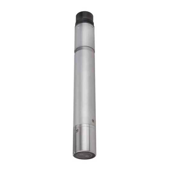
Page 6: Structure Of The Visoturb ® 700 Iq (Sw) Turbidity Sensor
® Overview VisoTurb 700 IQ (SW) ® Structure of the VisoTurb 700 IQ (SW) turbidity sensor Fig. 1-2 Structure of the turbidity sensor (example: VisoTurb® 700 IQ) Shaft Connection head Optical measurement window Sapphire disc with ultrasound cleaning system Recommended fields of application ®... -
Page 7: Features Of The Visoturb ® 700 Iq (Sw)
® VisoTurb 700 IQ (SW) Overview ® Features of the VisoTurb 700 IQ (SW) ® Turbidity measurement The turbidity measurement in aqueous media with the VisoTurb according to 700 IQ (SW) is conducted nephelometrically in accordance with EN EN ISO 7027 ISO 7027. - Page 8 ® Overview VisoTurb 700 IQ (SW) 1 - 4 ba57301e07 07/2010...
-
Page 9: Safety Instructions
® VisoTurb 700 IQ (SW) Safety instructions Safety instructions This component operating manual contains special instructions that ® must be followed during the operation of the VisoTurb 700 IQ (SW) turbidity sensor. Thus, it is essential to read this component operating manual before carrying out any work using this sensor. -
Page 10: Authorized Use
7 T ECHNICAL DATA The specified temperature (chapter 7 T ) must be ECHNICAL DATA maintained during the operation and transport of the sensor. CAUTION The sensor may only be opened by specialists authorized by WTW. 2 - 2 ba57301e07 07/2010... - Page 11 ® VisoTurb 700 IQ (SW) Safety instructions Safe operation If safe operation is no longer possible, the sensor must be taken out of operation and secured against inadvertent operation. Safe operation is no longer possible if the sensor: has been damaged in transport has been stored under adverse conditions for a lengthy period of time is visibly damaged...
- Page 12 ® Safety instructions VisoTurb 700 IQ (SW) 2 - 4 ba57301e07 07/2010...
-
Page 13: Commissioning
® VisoTurb 700 IQ (SW) Commissioning Commissioning Scope of delivery ® VisoTurb 700 IQ (SW) turbidity/total suspended solids sensor Operating manual Installation 3.2.1 General information ® The measuring principle of the VisoTurb 700 IQ (SW) (optical scattered light measurement) places particular requirements on the measurement location and on the installation of the sensor. -
Page 14: Flow Direction
® Commissioning VisoTurb 700 IQ (SW) 3.2.2 Flow direction As a general rule, the sapphire disc should be positioned clearly against the current in flowing media (angle of attack approx. 20 to 45 °). Exception: If there are high quantities of foreign bodies with fibrous or large surfaces, as for example hairs, strings or leaves, it may be of advantage to incline the sensor in the direction of the flow so that the sapphire disc does not face the flow. -
Page 15: Sensor Orientation
° Infrared beam VisoTurb 700 IQ S Fig. 3-2 Direction of the infrared beam relative to the marking The angle of incidence to the ground and walls can be affected by rotating the sensor around its longitudinal axis. The sensor should be turned so that as little light as possible that is scattered or reflected by the wall or ground strikes the measurement window again. -
Page 16: Distances From The Ground And Wall
® Commissioning VisoTurb 700 IQ (SW) 3.2.5 Distances from the ground and wall Note In cases of low turbidity (< 100 FNU), the effect of the measuring environment can simulate higher turbidity or an increased level of total suspended solids. The effect of the measurement environment can be reduced by ensuring the optimum conditions (see section 3.2.1). -
Page 17: Installation Examples
® VisoTurb 700 IQ (SW) Commissioning Installation examples ® As a rule, the VisoTurb 700 IQ (SW) will measure interference-free when the distances and angles etc. specified are observed. However, interferences at the measuring location (see section 3.2.1) may require special adaptations of the installation. -
Page 18: Measuring In An Open Channel (Range > 100 Fnu)
® Commissioning VisoTurb 700 IQ (SW) 3.3.2 Measuring in an open channel (range > 100 FNU) Example: In an open channel, the sensor can be immersed in the sample using Outlet of a waste water a wall mounting assembly, e.g. EH/W 170 wall mounting assembly, treatment plant (open (please note the minimum immersion depth). -
Page 19: Measurement In Pipelines
® VisoTurb 700 IQ (SW) Commissioning 3.3.3 Measurement in pipelines Note In cases of low turbidity (< 100 FNU), the effect of the measuring environment can simulate higher turbidity or an increased level of total suspended solids. The effect of the measurement environment can be reduced by ensuring the optimum conditions (see section 3.2.1). - Page 20 ® Commissioning VisoTurb 700 IQ (SW) Example: 90 ° pipe installation Fig. 3-6 Turbidity sensor in the pipe (90 °) The following points must be observed for a right-angled installation in the pipe (Fig. 3-6): Rotate the sensor so that the marking on the sensor points in the direction of the pipe axis Select a position where the pipe diameter is as large as possible as the installation location (see section 3.2.5 D...
-
Page 21: Commissioning / Readiness For Measuring
® the VisoTurb 700 IQ SW. Information on this and other IQ S accessories is given in the WTW catalog and on the ENSOR Internet. Note How to connect the SACIQ (SW) sensor connection cable to the... - Page 22 Note Do not suspend the sensor on the sensor connection cable. Use a sensor holder or an armature. Information on this and other IQ S accessories is given in the WTW catalog and on the ENSOR Internet. Connecting the sensor...
-
Page 23: 700 Iq (Sw)
® VisoTurb 700 IQ (SW) Commissioning ® Setting table 3.4.2 VisoTurb 700 IQ (SW) Setting Selection/values Explanation Measuring mode – Turbidity unit Formazine Nephelometric Units – Turbidity unit Nephelometric Turbidity Units – Turbidity Unit Formazine mg/l SiO2 – Concentration of SiO in mg/l ppm SiO2 –... - Page 24 ® Commissioning VisoTurb 700 IQ (SW) Setting Selection/values Explanation AutoRange Measuring range for the measuring mode ppm SiO2 0 ... 0.400 ppm 0 ... 4.00 ppm (AutoRange = automatic changeover of the measuring range) 0 ... 40.0 ppm 0 ... 400 ppm 0 ...
- Page 25 ® VisoTurb 700 IQ (SW) Commissioning Setting Selection/values Explanation Quit The display switches to the next higher level without saving the new settings. Carrying out settings Switch to the main settings menu from the measured value display with . Then navigate to the setting menu (setting table) of the sensor. The exact procedure is described in the relevant IQ S ENSOR system operating manual.
- Page 26 ® Commissioning VisoTurb 700 IQ (SW) 3 - 14 ba57301e07 07/2010...
-
Page 27: Measuring
® VisoTurb 700 IQ (SW) Measuring Measuring ® The turbidity measurement in aqueous media with the VisoTurb 700 IQ (SW) is conducted nephelometrically in accordance with EN ISO 7027. The turbidity/total suspended solids sensor can also be used to determine the total suspended solids content in the sample. The appropriate correlation for the given application can be determined via a reference measurement. -
Page 28: Calibration
® Measuring VisoTurb 700 IQ (SW) Calibration 4.2.1 General information Why calibrate? The following factors can change with time and affect the measurement results: the optical characteristics, e.g. color and particle size, and the density of the measuring medium (e.g. dependent on the season) the conditions at the measuring location (e.g. -
Page 29: Application Offset
® VisoTurb 700 IQ (SW) Measuring 4.2.2 Application offset In an optimum installation (sufficient distance to the walls, walls made of dark material), the effect of the measurement environment is negligibly small. If an optimum installation is not feasible due to local circumstances, interference effects can be compensated by a measured value correction. -
Page 30: User Calibration For Measuring The Total Suspended Solids (G/L Tss)
® Measuring VisoTurb 700 IQ (SW) Marking in this direction approx. 10 cm approx. 20 cm Fig. 4-1 Ideal measurement environment for the application offset 4.2.3 User calibration for measuring the total suspended solids (g/l TSS) The turbidity values of the TSS measurement are converted into FNU units for the concentration of dry substance. - Page 31 ® VisoTurb 700 IQ (SW) Measuring Determine and note the concentration of total suspended solids in the sample according to a reference procedure (e.g. gravimetric according to DIN 38414). Switch to the setting table of the turbidity sensor. Select the value range for the total suspended solids contents determined during the reference measurement in the TSS range field.
- Page 32 ® Measuring VisoTurb 700 IQ (SW) Setting Selection/values Explanation Turbidity range 0 ... 0.400 FNU Range for the entry of the turbidity value. 0 ... 4.00 FNU Select the smallest possible range in order to 0 ... 40.0 FNU enter the turbidity value in the Turbidity value field as precisely as possible.
-
Page 33: Maintenance, Cleaning, Accessories
® VisoTurb 700 IQ (SW) Maintenance, cleaning, accessories Maintenance, cleaning, accessories General information WARNING Contact with the sample can be dangerous for the user! Depending on the type of sample, suitable protective measures must be taken (protective clothing, protective goggles, etc.). ®... - Page 34 ® Maintenance, cleaning, accessories VisoTurb 700 IQ (SW) Note We do not recommend to unscrew the sensor from the sensor connection cable when cleaning the sensor shaft and membrane. Otherwise, moisture and/or dirt can get into the plug connection where they can cause contact problems.
-
Page 35: Accessories
Maintenance, cleaning, accessories Accessories Description Model Order no. Screwable plug for sensor SACIQ-Plug 480 065 connection cable Note Information on other IQ S accessories is given in the WTW ENSOR catalog and on the Internet. ba57301e07 07/2010 5 - 3... - Page 36 ® Maintenance, cleaning, accessories VisoTurb 700 IQ (SW) 5 - 4 ba57301e07 07/2010...
-
Page 37: What To Do If
® VisoTurb 700 IQ (SW) What to do if ... What to do if ... The sensor Cause Remedy automatically switches – The available power is – Install another power supply itself on and off sufficient for the initialization of module as close as possible periodically after ®... - Page 38 ® What to do if ... VisoTurb 700 IQ (SW) Measured values too Cause Remedy high – Gas bubbles in the medium are – Check the installation position in front of the sapphire disc of the sensor (see section 3.2 and section 3.3) –...
-
Page 39: Technical Data
® VisoTurb 700 IQ (SW) Technical data Technical data Measuring characteristics Measuring principle Procedure for measuring scattered light measurement in accordance with EN ISO 7027 (DIN EN 27027 or ISO 7027): 90 ° measuring angle Measurement in formazine nephelometric units, FNU Conversion of the values to: –... -
Page 40: Application Characteristics
® Technical data VisoTurb 700 IQ (SW) Accuracy Process variation coefficient < 1 % in the range to 2000 FNU according to DIN 38402 part 51 Repeatability limit or repeatability < 0.015 % or according to DIN ISO 5725 or min. -
Page 41: General Data
® VisoTurb 700 IQ (SW) Technical data General data VisoTurb 700 IQ: Dimensions 40.0 Socket SACIQ... VisoTurb 700 IQ SW: 40.0 Socket SACIQ... 59.5 ® Weight (without sensor VisoTurb 700 IQ approx. 990 g connection cable) ® VisoTurb 700 IQ SW approx. -
Page 42: Electrical Data
® Technical data VisoTurb 700 IQ (SW) Cleaning system Ultrasound principle Automatic sensor Recognition of a measurement malfunction monitoring Identification of any failure of the cleaning system (SensCheck function) Instrument safety Applicable norms – EN 61010-1 – UL 3111-1 – CAN/CSA C22.2 No. 1010.1 Electrical data Nominal voltage max. -
Page 43: Indexes
® VisoTurb 700 IQ (SW) Indexes Indexes Explanation of the messages This chapter contains a list of all the message codes and related message texts that can occur in the log book of the IQ S ENSOR ® system for the VisoTurb 700 IQ (SW) sensor. -
Page 44: Info Messages
* Power unit(s) overloaded, add power unit(s) * Check terminal and module connections * Defective components, replace components ES1341 Component hardware defective * Contact WTW ESD341 SensCheck: Measurement interfered * Submerse sensor in sample * Select bubble-free spot for measurement... -
Page 45: Status Info
® VisoTurb 700 IQ (SW) Indexes Status info The status info is a piece of coded information about the current state of a sensor. Each sensor sends this status info to the controller. The status info of sensors consists of 32 bits, each of which can have the value 0 or 1. - Page 46 ® Indexes VisoTurb 700 IQ (SW) 8 - 4 ba57301e07 07/2010...
- Page 48 Wissenschaftlich-Technische Werkstätten GmbH Dr.-Karl-Slevogt-Straße 1 D-82362 Weilheim Germany Tel: +49 (0) 881 183-0 +49 (0) 881 183-100 Fax: +49 (0) 881 183-420 E-Mail: Info@WTW.com Internet: http://www.WTW.com...
Need help?
Do you have a question about the VisoTurb 700 IQ and is the answer not in the manual?
Questions and answers