wtw ViSolid 700 IQ Operating Manual
Total suspended solids sensors
Hide thumbs
Also See for ViSolid 700 IQ:
- Operating manual (48 pages) ,
- Manual (28 pages) ,
- Operating manual (44 pages)

Related Manuals for wtw ViSolid 700 IQ


Summary of Contents for wtw ViSolid 700 IQ
- Page 1 OPERATING MANUAL ba57302e07 04/2015 ViSolid 700 IQ ViSolid 700 IQ SW ® ViSolid 700 IQ (SW) IQ S TOTAL SUSPENDED SOLIDS SENSOR ENSOR...
- Page 2 Copyright © 2016 Xylem Analytics Germany GmbH Printed in Germany.
-
Page 3: Table Of Contents
® ViSolid 700 IQ (SW) Contents ® ViSolid 700 IQ (SW) - Contents Overview ........2-1 How to use this component operating manual . - Page 4 ® Contents ViSolid 700 IQ (SW) What to do if ........7-1 Technical data .
-
Page 5: Overview
® ViSolid 700 IQ (SW) Overview Overview How to use this component operating manual Structure of the IQ Sensor Net Operating Manual IQ S ENSOR operating manual System Operating Manual (Ring Binder) IQ Sensor MIQ Module MIQ Terminal Operating Operating Operating Manual Manual... -
Page 6: Structure Of The Visolid ® 700 Iq (Sw) Total Suspended
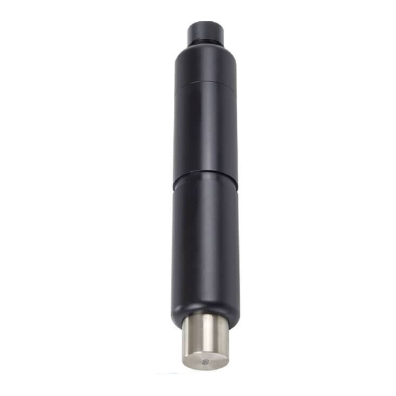
® Overview ViSolid 700 IQ (SW) ® Structure of the ViSolid 700 IQ (SW) total suspended solids sensor ® Fig. 1-2 Structure of the total suspended solids sensor (example: ViSolid 700 IQ) Shaft Connection head Optical measurement window made of sapphire Recommended fields of application ®... - Page 7 ® ViSolid 700 IQ (SW) Overview ® Features of the ViSolid 700 IQ (SW) Total suspended solids The measurement of the total suspended solids in aqueous media with ® measurement the ViSolid 700 IQ (SW) is carried out as a scattered light measurement.
- Page 8 ® Overview ViSolid 700 IQ (SW) 1 - 4 ba57302e07 04/2015...
-
Page 9: Safety Instructions
® ViSolid 700 IQ (SW) Safety instructions Safety instructions This component operating manual contains special instructions that must be followed in the operation of the total suspended solids sensor ® ViSolid 700 IQ (SW). Thus, it is essential to read this component operating manual before carrying out any work using this sensor. -
Page 10: Authorized Use
7 T ECHNICAL DATA The specified temperature (chapter 7 T ) must be ECHNICAL DATA maintained during the operation and transport of the sensor. CAUTION The sensor may only be opened by specialists authorized by WTW. 2 - 2 ba57302e07 04/2015... - Page 11 ® ViSolid 700 IQ (SW) Safety instructions Safe operation If safe operation is no longer possible, the sensor must be taken out of operation and secured against inadvertent operation. Safe operation is no longer possible if the sensor: has been damaged in transport ...
- Page 12 ® Safety instructions ViSolid 700 IQ (SW) 2 - 4 ba57302e07 04/2015...
-
Page 13: Commissioning
® ViSolid 700 IQ (SW) Commissioning Commissioning Scope of delivery ® Total suspended solids sensor, ViSolid 700 IQ (SW) Operating manual Installation 3.2.1 General information ® The measuring principle of the ViSolid 700 IQ (SW) (scattered light measurement) places specific requirements on the measurement location and on the installation of the sensor. -
Page 14: Flow Direction
® Commissioning ViSolid 700 IQ (SW) 3.2.2 Flow direction Generally, in flowing media, the measurement window should be clearly pitched towards the flow (angle of incidence approx. 20 to 45 °). Exception: If there is a high proportion of foreign bodies with fibrous or flat profiles such as, e.g. -
Page 15: Sensor Orientation
Marking in this direction Infrared beam ViSolid 700 IQ SW Fig. 3-2 Direction of the infrared beam relative to the marking The angle of incidence to the ground and walls can be affected by rotating the sensor around its longitudinal axis. The sensor should be turned so that as little light as possible that is scattered or reflected by the wall or ground strikes the measurement window again. -
Page 16: Distances From The Ground And Wall
® Commissioning ViSolid 700 IQ (SW) 3.2.5 Distances from the ground and wall Note If there is a low level of total suspended solids (< 2 g/l SiO2 or < 1 g/l TSS), the effects of the measurement environment can simulate a higher content of total suspended solids. -
Page 17: Installation Examples
® ViSolid 700 IQ (SW) Commissioning Installation examples ® As a rule, the ViSolid 700 IQ (SW) will measure interference-free when the distances and angles etc. specified are observed. However, interferences at the measuring location (see section 3.2.1) may require special adaptations of the installation. - Page 18 ® Commissioning ViSolid 700 IQ (SW) Measurement in a In an open channel, the sensor can be immersed in the sample using channel a wall mounting assembly, e.g. EH/W 170 wall mounting assembly, (please note the minimum immersion depth). Mount the sensor rigidly in the channel. At the same time, tilt the sensor approx.
-
Page 19: Measurement In Pipelines
® ViSolid 700 IQ (SW) Commissioning 3.3.2 Measurement in pipelines Note If there is a low level of total suspended solids (< 2 g/l SiO2 or < 1 g/l TSS), the effects of the measurement environment can simulate a higher content of total suspended solids. The effect of the measurement environment can be reduced by ensuring the optimum conditions (see section 3.2.1). - Page 20 ® Commissioning ViSolid 700 IQ (SW) Note For exceptions to the direction of flow, see section 3.2.2 F DIRECTION 3 - 8 ba57302e07 04/2015...
- Page 21 ® ViSolid 700 IQ (SW) Commissioning Example: Marking aid 90 ° pipe installation in this direction ADA-DF 9 EBS 700-DU/N Infrared beam Fig. 3-6 Total suspended solids sensor in a pipe (90 °) The following points must be observed for a right-angled installation in the pipe (Fig.
-
Page 22: Commissioning / Readiness For Measuring
ViSolid 700 IQ SW. Information on this and other IQ S ENSOR accessories is given in the WTW catalog and on the Internet. Note How to connect the SACIQ (SW) sensor connection cable to the terminal strip of an MIQ module is described in chapter 3 I... - Page 23 Note Do not suspend the sensor on the sensor connection cable. Use a sensor holder or an armature. Information on this and other IQ S accessories is given in the WTW catalog and on the ENSOR Internet. Connecting the sensor...
-
Page 24: Selecting The Measuring Mode
® Commissioning ViSolid 700 IQ (SW) 3.4.2 Selecting the Measuring mode Specify the following data in the Measuring mode setting Matrix type (1 or 2) Display (TSS or SiO2) Unit (g/l or %) Determining the matrix Determine the matrix type for your application with the aid of the type following table: Measurement in g/l TSS... -
Page 25: 700 Iq (Sw)
® ViSolid 700 IQ (SW) Commissioning ® Setting table 3.4.3 ViSolid 700 IQ (SW) Setting Selection/values Explanation Matrix type1:g/l TSS Measuring mode – Content of total suspended solids in g/l (see section 3.4.2) Matrix type1:% TSS – Content of total suspended solids in % ... - Page 26 ® Commissioning ViSolid 700 IQ (SW) Setting Selection/values Explanation Basic settings TSS measuring Selection between the use of the basic mode: settings and the entry of calibration value Menu selection: pairs. User calibration For the selection of the value pairs, fields ...
- Page 27 ® ViSolid 700 IQ (SW) Commissioning Setting Selection/values Explanation 0 ... 400.0 mg/l Measuring mode Measuring ranges for the SiO2: Matrixtype1:g/l SiO2 measuring mode 0 ... 4000 mg/l Measuring ranges 0 ... 25.00 g/l 0 ... 400.0 ppm Measuring ranges for the Matrix type1:% SiO2 measuring mode ...
- Page 28 ® Commissioning ViSolid 700 IQ (SW) 3 - 16 ba57302e07 04/2015...
-
Page 29: Measuring
® ViSolid 700 IQ (SW) Measuring Measuring ® The ViSolid 700 IQ (SW) measures the light scattered and reflected by the total suspended solids in the measuring medium. The level of total suspended solids that corresponds to the amount of light measured is displayed. -
Page 30: Calibration For Tss Measurement
® Measuring ViSolid 700 IQ (SW) Calibration for TSS measurement 4.2.1 General information Why calibrate? The following factors can change with time and affect the measurement results: the optical characteristics, e.g. color and particle size, and the density of the measuring medium (e.g. dependent on the season) ... -
Page 31: Default Calibration
® ViSolid 700 IQ (SW) Measuring 4.2.2 Default calibration Default calibration for The factory calibration curve for matrix type 1 was determined by matrix type 1 measurements of typical activated and return slurries and can be used for similar applications after adaptation of the Correction factor setting (see section 4.2.3). - Page 32 ® Measuring ViSolid 700 IQ (SW) Default calibration for The factory calibration curve for matrix type 2 was determined by matrix type 2 measurements of typical decaying slurries and can be used for similar applications after adaptation of the Correction factor setting (see section 4.2.3).
-
Page 33: Correction Factor
® ViSolid 700 IQ (SW) Measuring 4.2.3 Correction factor The setting of the Correction factor provides a simple option for adapting the calibration to the current conditions. With the Correction factor setting you correct the measured value and have it indicated on the display. A change of the Correction factor setting is practical if the measured ®... - Page 34 ® Measuring ViSolid 700 IQ (SW) Determining the Bring the sensor into the measuring position. Correction factor In the setting table of the TSS sensor, note down the currently set Correction factor as the value for F Switch to the measured value display with <M>. When the measured value is stable, read the TSS value, convert it into the unit (g/l) if necessary, and note it down as the value for Sv.
-
Page 35: User Calibration
® ViSolid 700 IQ (SW) Measuring 4.2.4 User calibration The displayed values of total suspended solids are calculated with the aid of the stored calibration data. In the g/l TSS measuring mode, the value g/l SiO2 marked with "#" is displayed as the secondary measured value. - Page 36 ® Measuring ViSolid 700 IQ (SW) Note A measurement of the total suspended solids will deliver ever more accurate measurement results the closer the composition of the measuring medium corresponds to the status at the time of the calibration. If there is a fundamental change of the characteristics of the sample, a new calibration may be necessary.
- Page 37 ® ViSolid 700 IQ (SW) Measuring Sort the value pairs in descending order and, if necessary, enter them in a table and diagram (see chapter 9). Note Below the smallest value, the calibration curve is extended to the zero point and, above the largest value, it is extended to the end of the measuring range.
- Page 38 ® Measuring ViSolid 700 IQ (SW) Select the TSS value 1 menu item with <> and <OK>. Enter the value for the contents of total suspended solids (TSS in g/l) from the reference measurement with <> and <OK>. Select the SiO2 value 1 menu item with <> and <OK>. Enter the associated SiO2 value (SiO2 in g/l) measured with ®...
-
Page 39: Maintenance, Cleaning, Accessories
® ViSolid 700 IQ (SW) Maintenance, cleaning, accessories Maintenance, cleaning, accessories General information WARNING Contact with the sample can be dangerous for the user! Depending on the type of sample, suitable protective measures must be taken (protective clothing, protective goggles, etc.). ®... - Page 40 ® Maintenance, cleaning, accessories ViSolid 700 IQ (SW) Note We do not recommend unscrewing the sensor from the sensor connection cable when cleaning the sensor shaft and measurement window. Otherwise, moisture and/or dirt can get into the plug connection where it can cause contact problems. If you need to disconnect the sensor from the sensor connection cable, please note the following points: ...
-
Page 41: Accessories
Maintenance, cleaning, accessories Accessories Description Model Order no. Screwable plug for sensor SACIQ-Plug 480 065 connection cable Note Information on other IQ S accessories is given in the WTW ENSOR catalog and on the Internet. ba57302e07 04/2015 5 - 3... - Page 42 ® Maintenance, cleaning, accessories ViSolid 700 IQ (SW) 5 - 4 ba57302e07 04/2015...
-
Page 43: What To Do If
® ViSolid 700 IQ (SW) What to do if ... What to do if ... Mechanical damage to Cause Remedy the sensor – Return the sensor Display always shows Cause Remedy "0" – First calibration value pair – Enter the TSS value for the incomplete first calibration value pair TSS display does not... - Page 44 ® What to do if ... ViSolid 700 IQ (SW) Measured value Cause Remedy fluctuating heavily – There are bubbles of gas in the – Check the installation medium in front of the position of the sensor (see measurement windows section 3.2 and section 3.3) –...
-
Page 45: Technical Data
® ViSolid 700 IQ (SW) Technical data Technical data Measuring characteristics Measuring principle Procedure for measuring scattered light. Measurement in following units: g/l TSS (total suspended solids) % TSS (total suspended solids) g/l SiO % SiO Measuring ranges and Measured parameter Measuring ranges... -
Page 46: Application Characteristics
® Technical data ViSolid 700 IQ (SW) Application characteristics Allowed Measuring medium 0 °C ... + 60 °C (32 ... 140 °F) temperature range Storage/transport - 5 °C ... + 65 °C (23 ... 149 °F) Allowed pH range of the 4 ... -
Page 47: General Data
® ViSolid 700 IQ (SW) Technical data General data ViSolid 700 IQ: Dimensions (in mm) 40.0 Socket SACIQ... ViSolid 700 IQ SW: 40.0 Socket SACIQ... 59.5 ® Weight (without sensor ViSolid 700 IQ approx. 990 g connection cable) ® VisoTurb 700 IQ SW approx. -
Page 48: Electrical Data
® Technical data ViSolid 700 IQ (SW) Material Shaft V4A stainless steel 1.4571 * Measurement window Sapphire Plug head connector housing ® Plug, 3-pole ETFE (blue) Tefzel * Stainless steel can be susceptible to corrosion at chloride concentrations of ≥ 500 mg/l and more. Cleaning system Ultrasound principle ... -
Page 49: Indexes
® ViSolid 700 IQ (SW) Indexes Indexes Explanation of the messages This chapter contains a list of all the message codes and related message texts that can occur in the log book of the IQ S ENSOR ® system for the ViSolid 700 IQ (SW) sensor. -
Page 50: Info Messages
® Indexes ViSolid 700 IQ (SW) Message code Message text EC2342 User calibration error, check TSS/SiO2 pairs of variates * All TSS values within measuring range? (see operating manual) * At least one value pair entered? * All TSS and SiO2 values entered? * All TSS/SiO2 pairs in descending order? * Pair 1 = highest TSS and SiO2 value? EI1342... -
Page 51: Status Info
® ViSolid 700 IQ (SW) Indexes Status info The status info is a piece of coded information about the current state of a sensor. Each sensor sends this status info to the controller. The status info of sensors consists of 32 bits, each of which can have the value 0 or 1. - Page 52 ® Indexes ViSolid 700 IQ (SW) 8 - 4 ba57302e07 04/2015...
-
Page 53: Appendix
® ViSolid 700 IQ (SW) Appendix Appendix Check calibration values By checking the value pairs, possible calibration errors can already be avoided before the entry of the calibration value pairs. Carry out a check using the EC2342 message text: * All TSS values within measuring range? (see operating manual) * At least one value pair entered? * All TSS and SiO2 values entered? - Page 54 ® Appendix ViSolid 700 IQ (SW) 9 - 2 ba57302e07 04/2015...
- Page 56 For more information on how Xylem can help you, go to xyleminc.com. ® Service address: Xylem Analytics Germany Sales GmbH & Co. KG Dr.-Karl-Slevogt-Str. 1 82362 Weilheim Germany Tel.: +49 881 183-325 Fax: +49 881 183-414 E-Mail wtw.rma@xyleminc.com Internet: www.WTW.com Xylem Analytics Germany GmbH Dr.-Karl-Slevogt-Str. 1 82362 Weilheim Germany...
Need help?
Do you have a question about the ViSolid 700 IQ and is the answer not in the manual?
Questions and answers