wtw VisoTurb 700 IQ Operating Manual
Iq sensor net turbidity / total suspended solids sensor
Hide thumbs
Also See for VisoTurb 700 IQ:
- Operating manual (56 pages) ,
- Manual (28 pages) ,
- Operating manual (28 pages)
Table of Contents
Advertisement
Quick Links
Download this manual
See also:
Operating Manual
Advertisement
Table of Contents

Related Manuals for wtw VisoTurb 700 IQ


Summary of Contents for wtw VisoTurb 700 IQ
- Page 1 OPERATING MANUAL ba57301e09 06/2017 VisoTurb 700 IQ VisoTurb 700 IQ SW ® VisoTurb 700 IQ (SW) IQ S TURBIDITY / TOTAL SUSPENDED SOLIDS SENSOR ENSOR...
- Page 2 For the most recent version of the manual, please visit www.WTW.com. Weilheim 2017, WTW GmbH © Copyright Reproduction in whole - or even in part - is prohibited without the express written permission of WTW GmbH, Weilheim. Printed in Germany. ba57301e09 06/2017...
-
Page 3: Table Of Contents
® VisoTurb 700 IQ (SW) Contents ® VisoTurb 700 IQ (SW) - Contents ® VisoTurb 700 IQ (SW) - Inhaltsver- Overview ........1-5 How to use this component operating manual . - Page 4 ® Contents VisoTurb 700 IQ (SW) 4.2.3 User calibration for measurement of the total suspended solids (g/l TSS) ....4-26 Maintenance, cleaning, accessories ... . 5-29 General information .
-
Page 5: Overview
® VisoTurb 700 IQ (SW) Overview Overview How to use this component operating manual Structure of the IQ Sensor Net Operating Manual IQ S ENSOR operating manual System Operating Manual (Ring Binder) IQ Sensor MIQ Module MIQ Terminal Operating Operating Operating Manual Manual... -
Page 6: Recommended Fields Of Application
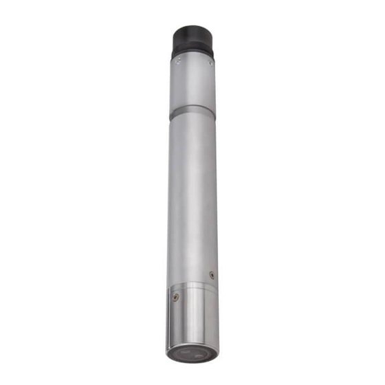
® Overview VisoTurb 700 IQ (SW) ® Structure of the VisoTurb 700 IQ (SW) turbidity sen- ® Fig. 1-2 Structure of the (Example: VisoTurb 700 IQ (SW)) turbidity sensor Shaft Connection head Optical measurement window Sapphire disc with ultrasound cleaning system Recommended fields of application ®... -
Page 7: Features Of The Visoturb ® 700 Iq (Sw)
® VisoTurb 700 IQ (SW) Overview ® Features of the VisoTurb 700 IQ (SW) Turbidity measurement The turbidity measurement in aqueous media with the ® according to VisoTurb 700 IQ (SW) is conducted nephelometrically in accordance EN ISO 7027 with EN ISO 7027. Total suspended solids The turbidity/total suspended solids sensor can also be used to deter- measurement... -
Page 8: Safety
® Safety VisoTurb 700 IQ (SW) Safety Safety information 2.1.1 Safety information in the operating manual This operating manual provides important information on the safe oper- ation of the product. Read this operating manual thoroughly and make yourself familiar with the product before putting it into operation or working with it. -
Page 9: Safe Operation
® VisoTurb 700 IQ (SW) Safety Safe operation 2.2.1 Authorized use ® The authorized use of the VisoTurb 700 IQ (SW) consists of its use as a sensor in the IQ S . Only the operation and running of the ENSOR sensor according to the instructions and technical specifications given in this operating manual is authorized (see chapter 7 T... -
Page 10: Commissioning
® Commissioning VisoTurb 700 IQ (SW) Commissioning Scope of delivery ® VisoTurb 700 IQ (SW) turbidity/total suspended solids sensor The sensor is fitted with protective caps Operating manual Installation 3.2.1 General information ® The measuring principle of the VisoTurb 700 IQ (SW) (optical scat- tered light measurement) places particular requirements on the mea- surement location and on the installation of the sensor. -
Page 11: Flow Direction
® VisoTurb 700 IQ (SW) Commissioning 3.2.2 Flow direction As a general rule, the sapphire disc should be positioned clearly against the current in flowing media (angle of attack approx. 20 to 45 °). Exception: If there are high quantities of foreign bodies with fibrous or large surfaces, as for example hairs, strings or leaves, it may be of advantage to incline the sensor in the direction of the flow so that the sapphire disc does not face the flow. -
Page 12: Distances From The Ground And Walls
° Infrared beam VisoTurb 700 IQ SW Fig. 3-2 Direction of the infrared beam in relation to the marking The angle of incidence to the ground and walls can be affected by rotat- ing the sensor around its longitudinal axis. The sensor should be turned so that as little light as possible that is scattered or reflected by the walls or ground strikes the measurement window again. -
Page 13: Installation Examples
® VisoTurb 700 IQ (SW) Commissioning The following graphic indicates the minimum distances of the measure- ment windows to the ground or walls, which must be observed. The effect of the distances on the measured value was determined for var- ious wall materials in the case of a sensor placed vertically to the walls in drinking water (see drawing). -
Page 14: Measuring In An Open Basin Or Channel (Range > 100 Fnu)
® Commissioning VisoTurb 700 IQ (SW) 3.3.1 Measuring in an open basin or channel (range > 100 FNU) Example: The turbidity sensor can be immersed in the sample using a pendulum Outflow of mounting assembly, e.g. pendulum mounting assembly EH/P 170, preclarification (pay attention to the minimum immersion depth). - Page 15 ® VisoTurb 700 IQ (SW) Commissioning Marking ° in this direction Immersion depth min. 7 cm min. 10 cm min. 10 cm G r o min. 10 cm u n d Fig. 3-4 Turbidity sensor in the open channel with EH/W 170 fixture assembly for direct wall mounting.
-
Page 16: Measurement In Pipelines
® Commissioning VisoTurb 700 IQ (SW) 3.3.3 Measurement in pipelines In cases of low turbidity (< 100 FNU), the effect of the mea- suring environment can simulate higher turbidity or an increased level of total suspended solids. The effect of the measurement environment can be reduced by ensuring the optimum conditions (see section 3.2.1). - Page 17 ® VisoTurb 700 IQ (SW) Commissioning Interferences at the measuring location (see section 3.2.1) may require special adaptations of the installation. For exceptions to the direction of flow, see section 3.2.2 F DIRECTION Marking aid Example: in this direction 90 ° pipe installation EBS 700-DU/N Infrared beam Fig.
-
Page 18: Commissioning / Readiness For Measurement
700 IQ SW. Information on this and other IQ S ENSOR accessories is given in the WTW catalog and on the Internet. How to connect the sensor connection cable to the terminal strip of an MIQ module is described in chapter 3 I... - Page 19 Commissioning Do not suspend the sensor on the sensor connection cable. Use a sensor holder or armature. Information on this and other IQ S accessories is given in the WTW cat- ENSOR alog and on the Internet. Connecting the sensor...
-
Page 20: 700 Iq (Sw)
® Commissioning VisoTurb 700 IQ (SW) ® Setting table for the 3.4.2 VisoTurb 700 IQ (SW) Carrying out settings Using <S>, switch from the measured value display to the main menu of the settings. Then navigate to the setting menu (setting table) of the sensor.The exact procedure is given in the relevant IQ S ENSOR system operating manual. - Page 21 ® VisoTurb 700 IQ (SW) Commissioning Setting Selection/values Explanation AutoRange Measuring ranges for the measuring mode mg/l SiO2 0 ... 0.400 mg/l 0 ... 4.00 mg/l (AutoRange = automatic changeover of the 0 ... 40.0 mg/l measuring range) ...
- Page 22 ® Commissioning VisoTurb 700 IQ (SW) Setting Selection/values Explanation Application offset -20.00 ... +20.00 Correction value for compensation of envi- (units depend on ronmentally-dependent interferences. The measuring mode) value is added to the measured value (for details, see section 4.2.2). UlCleaning/ On / On Switch on or off the ultrasound cleaning and...
-
Page 23: Measuring
® VisoTurb 700 IQ (SW) Measuring Measuring The turbidity measurement in aqueous media with the ® VisoTurb 700 IQ (SW) is conducted nephelometrically in accordance with EN ISO 7027. The turbidity/total suspended solids sensor can also be used to deter- mine the total suspended solids content in the sample. -
Page 24: Application Offset
® Measuring VisoTurb 700 IQ (SW) ing the optimum conditions (see section 3.2.1) and can be compen- sated by an application offset (see section 4.2.2). For measurements of the total suspended solids, a user calibration is always required (see section 4.2.3). When to calibrate? A new user calibration is required if there is any change of the charac- teristics of the measuring medium or any change of the environment at... - Page 25 ® VisoTurb 700 IQ (SW) Measuring Depending on the test sample, the optical characteristics of the inner surface of the vessel can change greatly with time (biological films, lime deposits). This can affect the turbidity measurement. Repeat the application offset from time, also to check the effect of the surfaces if excessive turbidity val- ues are suspected.
-
Page 26: User Calibration For Measurement Of The Total Suspended Solids (G/L Tss)
® Measuring VisoTurb 700 IQ (SW) Marking in this direction approx. 10 cm approx. 20 cm Fig. 4-1 Ideal measurement environment for the application offset 4.2.3 User calibration for measurement of the total suspended solids (g/l TSS) The turbidity values of the total supspended solids measurement are converted into FNU units for the concentration of dry substance. - Page 27 ® VisoTurb 700 IQ (SW) Measuring Determine and note the concentration of total suspended sol- ids in the sample according to a reference procedure (e.g. gravimetric according to DIN 38414). Switch to the setting table of the turbidity sensor. Select the value range for the total suspended solids contents determined during the reference measurement in the TSS range field.
- Page 28 ® Measuring VisoTurb 700 IQ (SW) Setting Selection/values Explanation 0 ... 0,400 FNU Turbitity range Range for the entry of the turbidity value. 0 ... 4.00 FNU Select the smallest possible range in order to 0 ... 40.0 FNU enter the turbidity value in the Turbidity value ...
-
Page 29: Maintenance, Cleaning, Accessories
® VisoTurb 700 IQ (SW) Maintenance, cleaning, accessories Maintenance, cleaning, accessories General information CAUTION Contact with the sample can lead to danger to the user! Depend- ing on the type of sample, suitable protective measures must be taken (protective clothing, protective goggles, etc.). ®... -
Page 30: Accessories
® Maintenance, cleaning, accessories VisoTurb 700 IQ (SW) If you would like to disconnect the sensor from the sensor connection cable, please note the following points: Before disconnecting the sensor from the SACIQ (SW) sensor con- nection cable, remove any larger pieces of contamination from the sensor, particularly in the area of the plug connection (brush it off in a bucket of tapwater, wash it off with a hose or wipe it off with a cloth). - Page 31 ® VisoTurb 700 IQ (SW) Maintenance, cleaning, accessories Information on other IQ S accessories is given ENSOR in the WTW catalog and on the Internet. ba57301e09 06/2017...
-
Page 32: What To Do If
® What to do if ... VisoTurb 700 IQ (SW) What to do if ... The sensor Cause Remedy automatically switches – The available power is suffi- – Install another power supply itself on and off cient for the initialization of the module as close as possible periodically after ®... - Page 33 ® VisoTurb 700 IQ (SW) What to do if ... Measured values too Cause Remedy high Gas bubbles in the medium are in Check the mounting position of front of the sapphire disc the sensor (see section 3.2 and section 3.3) Light scattering on the walls –...
-
Page 34: Technical Data
® Technical data VisoTurb 700 IQ (SW) Technical data Measuring characteristics Measuring principle Procedure for scattered light measurement in accordance with EN ISO 7027 (DIN EN 27027 or ISO 7027): 90 ° measuring angle Measurement in formazine nephelometric units, FNU Measuring ranges and Measuring mode Measuring ranges... -
Page 35: Application Characteristics
® VisoTurb 700 IQ (SW) Technical data Accuracy Process variation coefficient < 1 % in the range to 2000 FNU according to DIN 38402 part 51 Repeatability limit or repeatability < 0.015 % or according to DIN ISO 5725 or min. -
Page 36: General Data
® Technical data VisoTurb 700 IQ (SW) General data VisoTurb 700 IQ: Dimensions 40.0 Socket SACIQ... VisoTurb 700 IQ SW: 40.0 Socket SACIQ... 59.5 Weight (without sensor ® VisoTurb 700 IQ approx. 990 g connection cable) ® VisoTurb 700 IQ SW approx. -
Page 37: Electrical Data
® VisoTurb 700 IQ (SW) Technical data Recognition of a measurement malfunction Automatic sensor monitoring Identification of any failure of the cleaning system (SensCheck function) Instrument safety Applicable norms – EN 61010-1 – UL 61010-1 – CAN/CSA C22.2#61010-1 Electrical data Nominal voltage (Details see chapter T... -
Page 38: Lists
® Lists VisoTurb 700 IQ (SW) Lists Explanation of the messages This chapter contains a list of all the message codes and related mes- ® sage texts for the VisoTurb 700 IQ (SW) sensor. Information on the contents and structure of the log book and ... -
Page 39: Informative Messages
® VisoTurb 700 IQ (SW) Lists Message code Message text EI4341 Operational voltage too low, no operation possible * Check installation and cable lengths, Follow installation instructions * Power supply module overloaded * Check terminal and module connections * Defective component, replace components ES1341 Component hardware defective... -
Page 40: Status Info
® Lists VisoTurb 700 IQ (SW) Status info The status info is a coded piece of information on the current status of a sensor. Each sensor sends this status info to the controller of the IQ S . The status info of sensors consists of 32 bits, each of ENSOR which can have the value 0 or 1. - Page 42 For more information on how Xylem can help you, go to xyleminc.com. ® Service address: Xylem Analytics Germany Sales GmbH & Co. KG Dr.-Karl-Slevogt-Str. 1 82362 Weilheim Germany Tel.: +49 881 183-325 Fax: +49 881 183-414 E-Mail wtw.rma@xyleminc.com Internet: www.WTW.com Xylem Analytics Germany GmbH Dr.-Karl-Slevogt-Str. 1 82362 Weilheim Germany...
Need help?
Do you have a question about the VisoTurb 700 IQ and is the answer not in the manual?
Questions and answers